Notice: In order to prevent internal damage to the PCM, the ignition must be OFF when disconnecting or reconnecting the PCM connector.
Service of the PCM should normally consist of either replacement of the PCM or EEPROM re-programming.
If the diagnostic procedures call for the PCM to be replaced, the PCM should be checked first to see if it is the correct part. DTC P0601 indicates the EEPROM programming has malfunctioned. When DTC P0601 is obtained, re-program the EEPROM.
The ignition should be OFF for at least 10 seconds before disconnecting power to the PCM so the IAC valve has time to move to the engine OFF position.
Removal Procedure
Important: Turn OFF the ignition switch to prevent internal PCM damage when disconnecting
or reconnecting power to the PCM. The following are examples of when the ignition
switch should be OFF:
• Battery cables • PCM electrical connectors • PCM fuses • Jumper cables
- Disconnect the negative battery cable.
- Remove the LH sound insulator. Refer to Instrument Panel Insulator Panel Replacement - Left Side in Instrument Panel, Gauges and Console.
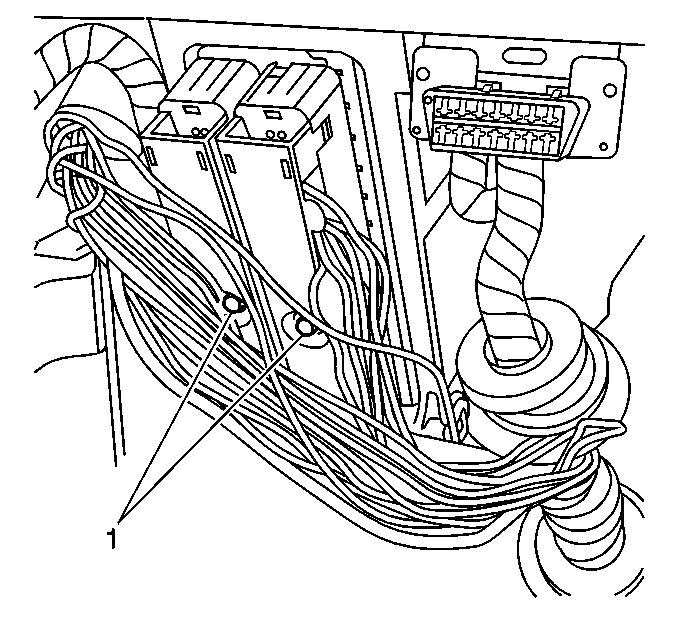
- Loosen the PCM electrical connectors screws (1).
- Disconnect the PCM electrical connectors.
- Open the PCM bracket latch.
- Slide the PCM from the PCM bracket.
Caution: Unless directed otherwise, the ignition and start switch must be in the OFF or LOCK position, and all electrical loads must be OFF before servicing any electrical component. Disconnect the negative battery cable to prevent an electrical spark should a tool or equipment come in contact with an exposed electrical terminal. Failure to follow these precautions may result in personal injury and/or damage to the vehicle or its components.


Notice: Do not touch the PCM connector pins or soldered components on the circuit board in order to prevent possible electrostatic discharge (ESD) damage. Do not remove the integrated circuit boards from the carrier.


Installation Procedure
Remove the new PCM from its packaging and check the service number to make sure it is the same number or updated number as the malfunctioning PCM.
- Slide the PCM into the PCM bracket until retainer locks PCM into position.
- Close the PCM bracket latch.
- Install the PCM electrical connectors.
- Tighten the PCM connector screws (1).
- Install the sound insulator. Refer to Instrument Panel Insulator Panel Replacement - Left Side in Instrument Panel, Gauges and Console.
- Connect the negative battery cable.
- Reprogram the PCM and perform the Crankshaft Position System Variation Learn .


Notice: Do not touch the PCM connector pins or soldered components on the circuit board in order to prevent possible electrostatic discharge (ESD) damage. Do not remove the integrated circuit boards from the carrier.


Notice: Use the correct fastener in the correct location. Replacement fasteners must be the correct part number for that application. Fasteners requiring replacement or fasteners requiring the use of thread locking compound or sealant are identified in the service procedure. Do not use paints, lubricants, or corrosion inhibitors on fasteners or fastener joint surfaces unless specified. These coatings affect fastener torque and joint clamping force and may damage the fastener. Use the correct tightening sequence and specifications when installing fasteners in order to avoid damage to parts and systems.
Tighten
Tighten the PCM electrical connector screws to 8N·m (71 lb in).
