System Diagnosis
Diagnosis for the temperature control portion of this system is based on malfunction codes stored in the heater-A/C control. When a code has been set, the man symbol on the right side of the heater-A/C control display will flash.
On-Board Diagnosis Mode
The CJ2 air conditioning is equipped with an on-board diagnostic feature which allows the heater-A/C control to detect certain system faults. The diagnostic feature may also be used to display certain data parameters. If the heater-A/C control detects a fault in the system, the man symbol will flash during the first 2 minutes of vehicle operation.
Entry into the diagnostic mode is gained by pressing in on both temperature knobs at the same time for 5 seconds. The following display modes are found within diagnostics:
| • | The diagnostic pointer |
| • | The diagnostic value |
By rotating the driver temperature knob one detent in either direction, the display is toggled between pointer and value. The value displayed is the decimal equivalent of the RAM contents. A 2 is formed using the minus sign and the leading 1 in order to display values over 199.
A diagnostic pointer mode is identified by a minus sign preceding the pointer number. The pointer provides an index, which identifies the corresponding diagnostic value. The diagnostic trouble codes (DTCs) reside under diagnostic pointer -00. The pointer will be set to this position upon initial entry into diagnostics. If more than one code exists, the codes will be displayed sequentially at a rate of 2 seconds per fault. Rotating the passenger temperature knob will switch the diagnostic pointers. A wrap around feature is provided if the pointer is continued past either end. Other data used by the computer resides under different diagnostic pointers, and may not be of use in observing the system. Press any mode button in order to exit the diagnostic mode.
Important: A 2-digit trouble code indicates the fault is current. A 3-digit trouble code indicates a history fault.
Clearing Codes
Press the A/C mode button in order to clear codes from the heater-A/C control.
Any of the following components may cause malfunction in the temperature controls:
| • | The refrigerant system |
| • | The electrical wiring connections |
| • | The vacuum connections |
| • | Faulty components that have mechanical problems, such as sticking valves |
As a part of the diagnostic process inspect the following components:
| • | The refrigerant, vacuum or mechanical systems. Refer to Vacuum Test . |
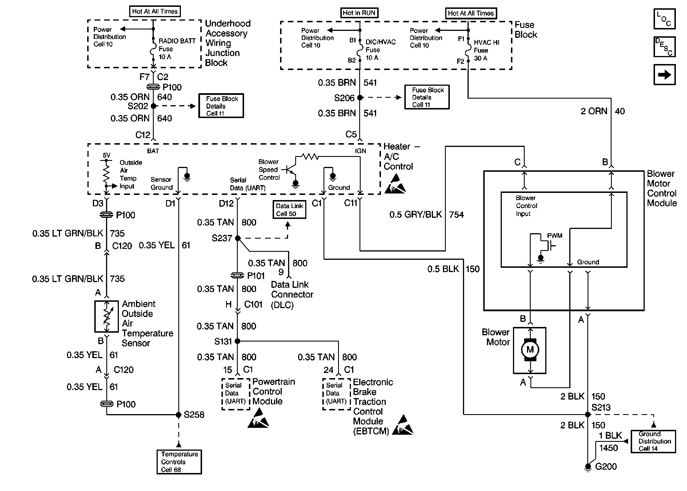
| • | The blower controls. Refer to

. |
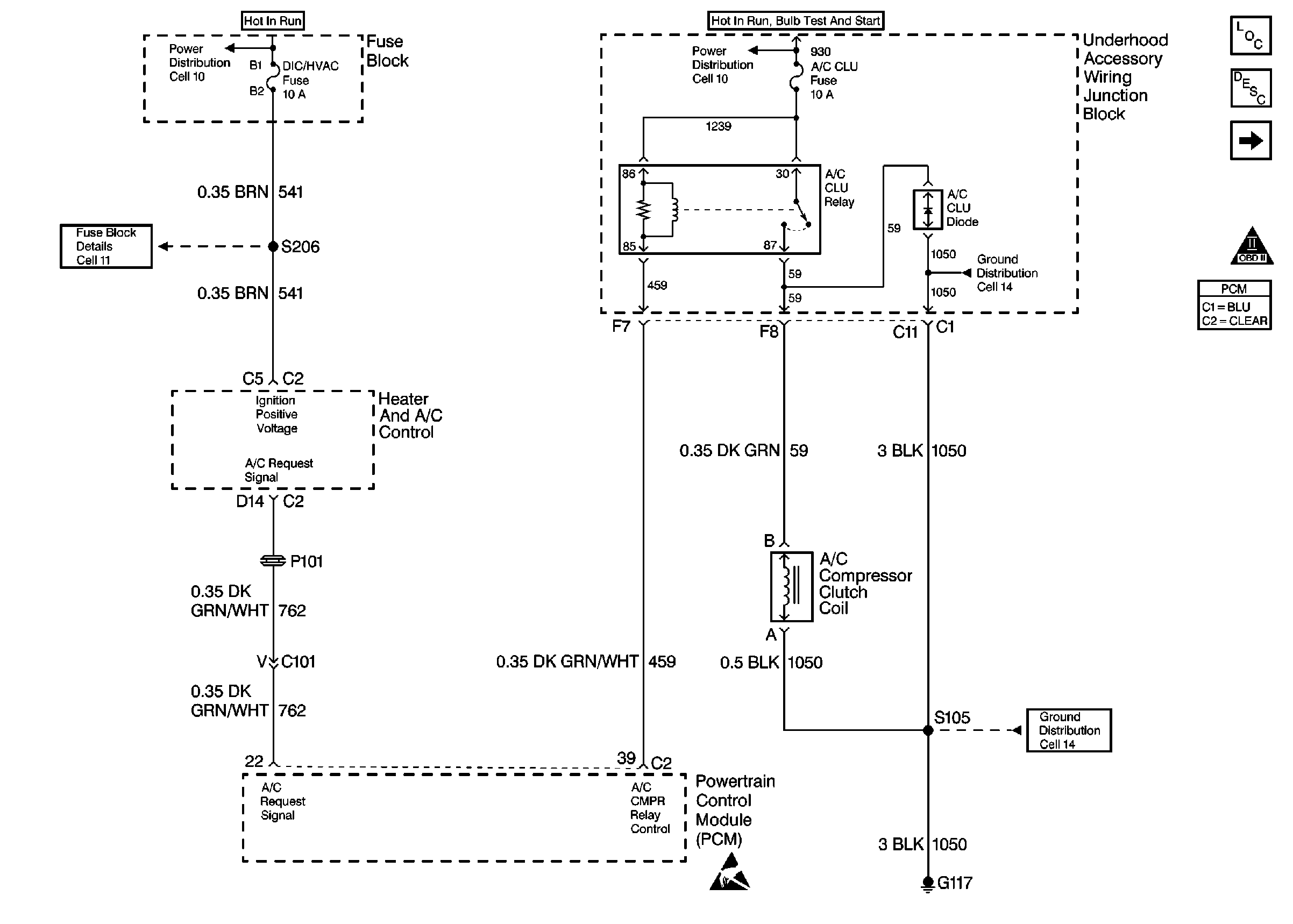
| • | The compressor controls. Refer to
Cell 67: RPO L36, L67
. |
| • | The air delivery controls. Refer to
Power and Grounds
. |
| • | The temperature controls. Refer to Electrical Diagnosis. |
| Complete the diagnostic procedure for the heater A/C control microprocessor. |
