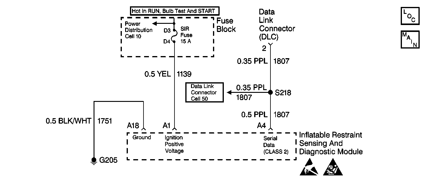
Circuit Description
The data link connector (DLC) is the provision for communicating with the inflatable restraint sensing and diagnostic module (SDM). The DLC is located under the instrument panel. The DLC supplies B+ and ground to the scan tool. The scan tool communicates with the SDM and other Class 2 modules that are on the same data line through CKT 1807. The scan tool is connected to the DLC in order to perform the following functions:
| • | Read the data list |
| • | Read diagnostic trouble codes (DTCs) |
| • | Clear DTCs |
When measurements are requested in this table, use J 39200 Digital Multimeter with the correct terminal adapter from J 35616 Connector Test Adapter Kit. When a check for proper connection is requested, refer to General Electrical Diagnosis Procedures in Wiring Systems. When a wire, connector or terminal repair is requested, use J-38125 Terminal Repair Kit and refer to Wiring Repair .
Test Description
-
This step checks to see if the scan tool operates properly.
-
This step checks for a proper connection at the data link connector (DLC).
-
This step checks for a proper connection at terminal A4 of the SDM wiring harness connector.
-
This step checks to see if there is an open or a high resistance in CKT 800.
-
This step checks to see if there is a short to ground in CKT 800.
-
This step determines if there is a short to B+ in CKT 800 or if there is a malfunctioning SDM.
Step | Action | Value(s) | Yes | No |
|---|---|---|---|---|
1 | Was the SIR Diagnostic System Check performed? | -- | ||
Does the scan tool turn ON? | -- | Go to Data Link Communications System Check in Data Link Communications | ||
3 | Attempt to establish communication with the same system on a different vehicle. Can communication be established? | -- | ||
Is the DLC damaged or corroded? | -- | |||
5 | Repair the DLC. Refer to Connector Repairs in Wiring Systems. Is the repair complete? | -- | -- | |
Is the connector damaged or corroded? | -- | |||
7 | Replace the SDM wiring harness connector. Refer to Wiring Repair . Is the repair complete? | -- | -- | |
8 | Check for a proper connection at terminal A4 of the SDM. Is the terminal damaged or corroded? | -- | ||
9 | Check for a proper connection at terminal A4 of the SDM. Is the terminal damaged or corroded? | -- | ||
10 | Replace the SDM. Refer to Inflatable Restraint Sensing and Diagnostic Module Replacement . Is the repair complete? | -- | -- | |
Use the J 39200 Digital Multimeter (SDM) to measure the resistance between terminal A4 of the SDM wiring harness connector and terminal 2 of the DLC. Is the measured resistance within the specified value? | 0-2 ohms | |||
12 |
Is the repair complete? | -- | -- | |
Use the J 39200 to measure the resistance between terminal 2 of the DLC connector and a known good ground. Is the measured resistance less than the specified value? | OL | |||
14 |
Is the repair complete? | -- | -- | |
Is the measured voltage less than the specified value? | 1 V | |||
16 |
Is the repair complete? | -- | -- | |
17 | Scan tool may be malfunctioning. Refer to the scan tool instruction manual. Has proper scan tool operation been verified? | -- | -- | |
18 | Replace the SDM. Refer to Inflatable Restraint Sensing and Diagnostic Module Replacement . Is the repair complete? | -- | -- | |
19 |
Have all the SIR components been reconnected and properly mounted? | -- | -- |
