Tools Required
| • | J 28467-B Universal Engine Support Fixture |
| • | J 35354 Seal Installer |
| • | J 37096 Flywheel Holder |
Removal Procedure
- Disconnect the negative battery cable. Refer to Battery Negative Cable Disconnection and Connection in Engine Electrical.
- Raise and support the vehicle. Refer to Lifting and Jacking the Vehicle in General Information.
- Drain the engine oil. Refer to Engine Oil and Oil Filter Replacement .
- Drain the cooling system. Refer to Cooling System Draining and Filling in Engine Cooling.
- Lower the vehicle.
- Loosen the water pump pulley bolts.
- Remove the drive belt tensioner. Refer to Drive Belt Tensioner Replacement .
- Remove the water pump pulley.
- Remove the radiator outlet hose. Refer to Radiator Outlet Hose Replacement in Engine Cooling.
- Remove the crankshaft balancer. Refer to Crankshaft Balancer Replacement .
- Pry out the crankshaft front oil seal with a flat bladed tool such as a large screwdriver. Use care to avoid damaging the crankshaft front oil seal bore or the crankshaft front oil seal contact surfaces.
- Disconnect the electrical connectors from the following:
- Remove the crankshaft position sensor shield.
- Lower the vehicle.
- Install the engine support fixture. Refer to Engine Support Fixture .
- Raise the vehicle.
- Remove the engine mount bracket for oil pan access. Refer to Engine Mount and Bracket Replacement .
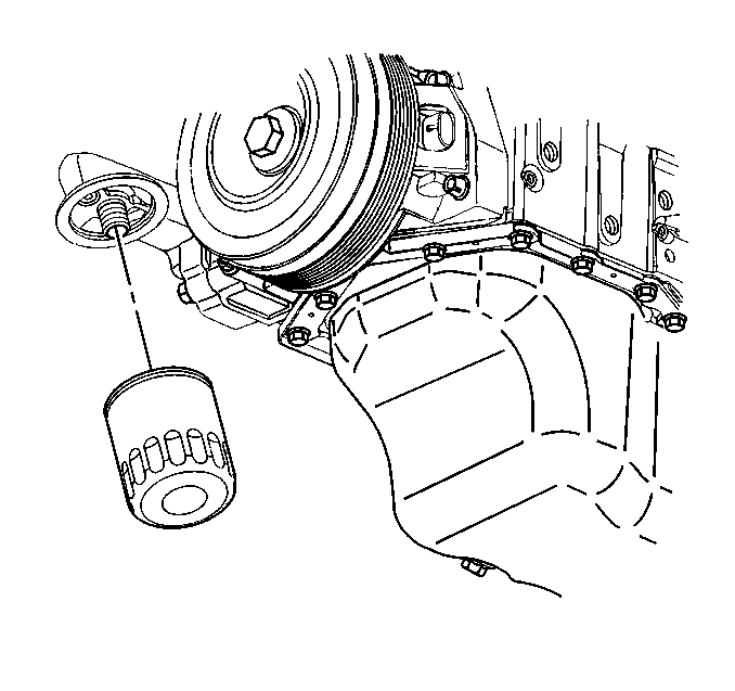
- Remove the oil filter.
- Disconnect the oil level sensor electrical connector.
- Remove the oil level sensor.
- Remove the oil pan-to-engine front cover bolts.
- Lower the oil pan and remove the oil pan-to-engine front cover bolts.
- Loosen the remaining oil pan bolts to gain access for the engine front cover removal. DO NOT remove the remaining oil pan bolts.
- Remove the crankshaft position sensor stops.
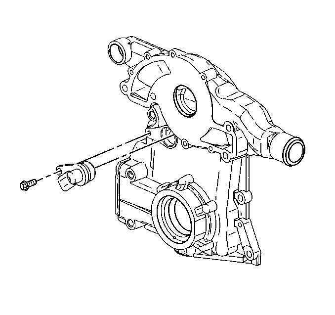
- Remove the crankshaft position sensor.
- Remove the engine front cover bolts.
- Remove the engine front cover with the oil filter adapter as one assembly.
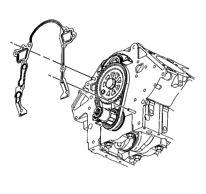
- Remove the engine front cover gasket.
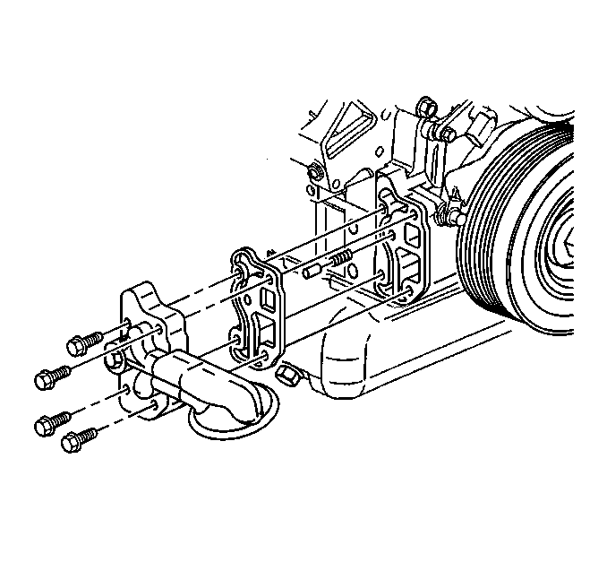
- If replacing the engine front cover, remove the oil filter adapter and pressure relief valve from the engine front cover.
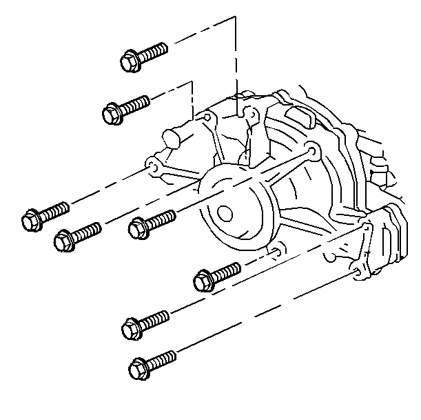
- If replacing the engine front cover, remove the water pump from the engine front cover.
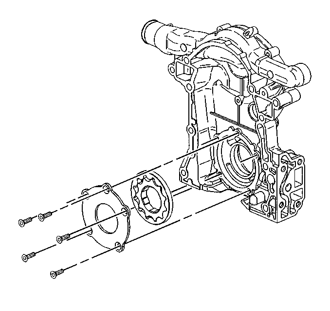
- If replacing the engine front cover, remove the oil pump cover and gear set from the engine front cover. Refer to Oil Pump Cover and Gear Set Replacement .
- Inspect the oil pump cover and gear set. Refer to Oil Pump Cleaning and Inspection in engine Mechanical - 3.8L Unit Repair.
- If replacing the engine front cover, remove the camshaft position sensor from the engine front cover.
- Inspect the timing chain for overall in and out movement. Maximum movement is 25.4 mm (1 in). Refer to Camshaft Timing Chain and Sprocket Cleaning and Inspection in Engine Mechanical - 3.8L Unit Repair.
- Inspect the sprockets for wear.
- Inspect the oil pan gasket. Replace the oil pan gasket if necessary.
- Clean the engine front cover mating surfaces.
Important: Be careful not to damage the crankshaft.
| • | Camshaft position (CMP) sensor |
| • | Crankshaft position (CKP) sensor |
| • | Oil pressor sensor |
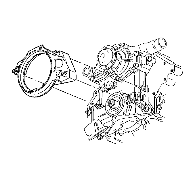
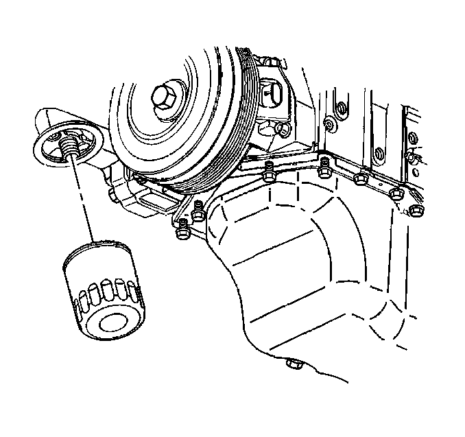
Important: The oil pan can be dropped slightly for engine front cover clearance if all pan bolts are loosened and the oil level sensor is removed.
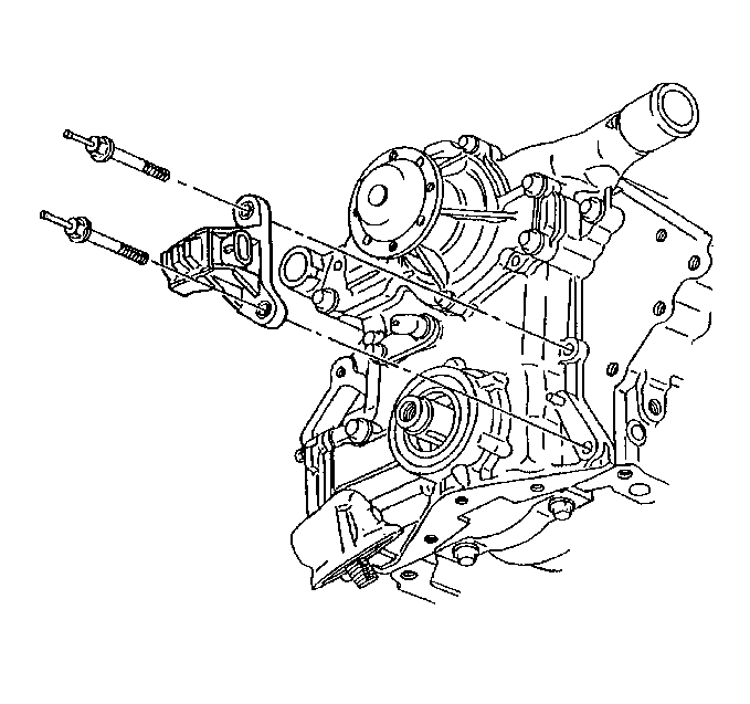
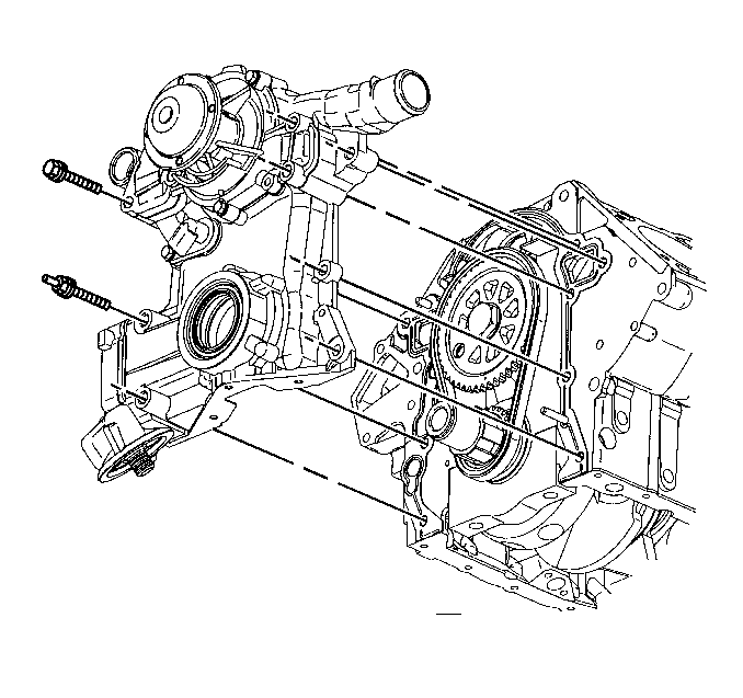
Installation Procedure
- If replacing the engine front cover, install the camshaft position sensor.
- Install the camshaft position bolt.
- If replacing the engine front cover, install the oil pump cover and gear set to the engine front cover. Refer to Oil Pump Cover and Gear Set Replacement .
- If replacing the engine front cover, install the water pump gasket and the water pump to the front cover.
- Install the water pump bolts to the water pump.
- If replacing the engine front cover, install the pressure relief valve, the oil filter adapter gasket and the oil filter adapter to the front cover.
- Install the oil filter adapter bolts to the oil filter adapter.
- Install the new engine front cover gasket. Ensure that the sealing surfaces are not damaged.
- Apply sealer GM P/N 12346004 (Canadian P/N 10953480) or equivalent to the bolt threads.
- Align the cogs on the crankshaft sprocket with the cogs on the oil pump gear set in the engine front cover.
- Install the engine front cover to the engine.
- Install the engine front cover bolts (1-7).
- Install the crankshaft position sensor.
- Install the crankshaft position sensor studs.
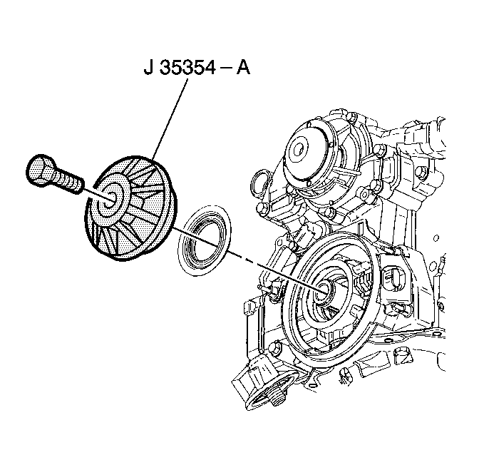
- Install the new engine front cover seal using J 35354 .
- Tighten the bolt until the crankshaft front oil seal is seated in the engine front cover.
- Remove the J 35354 .
- Install the oil pan-to-engine front cover bolts.
- Install the oil level sensor
- Connect the oil level sensor electrical connector.
- Install the engine mount bracket. Refer to Engine Mount and Bracket Replacement .
- Install the oil filter.
- Install the crankshaft position sensor shield.
- Connect the electrical connectors to the following:
- Install the crankshaft balancer. Refer to Crankshaft Balancer Replacement .
- Lower the vehicle.
- Remove the engine support fixture.
- Install the radiator outlet hose to the water pump. Refer to Radiator Outlet Hose Replacement in Engine Cooling.
- Install the water pump pulley.
- Install the water pump pulley bolts.
- Install the drive belt tensioner. Refer to Drive Belt Tensioner Replacement .
- Fill the cooling system. Refer to Cooling System Draining and Filling in Engine Cooling.
- Fill the crankcase with engine oil. Refer to Engine Oil and Oil Filter Replacement .
- Connect the negative battery cable. Refer to Battery Negative Cable Disconnection and Connection in Engine Electrical.
- Inspect for leaks.
- Perform the CKP system variation learn procedure. Refer to Crankshaft Position System Variation Learn in Engine Controls - 3.8L.

Notice: Use the correct fastener in the correct location. Replacement fasteners must be the correct part number for that application. Fasteners requiring replacement or fasteners requiring the use of thread locking compound or sealant are identified in the service procedure. Do not use paints, lubricants, or corrosion inhibitors on fasteners or fastener joint surfaces unless specified. These coatings affect fastener torque and joint clamping force and may damage the fastener. Use the correct tightening sequence and specifications when installing fasteners in order to avoid damage to parts and systems.
Tighten
Tighten the bolts to 10 N·m (89 lb in).


Tighten
| • | Tighten the long water pump bolts to 34 N·m (25 lb ft). |
| • | Tighten the short water pump bolts to 22 N·m (16 lb ft). |

Tighten
Tighten the bolts to 30 N·m (22 lb ft).


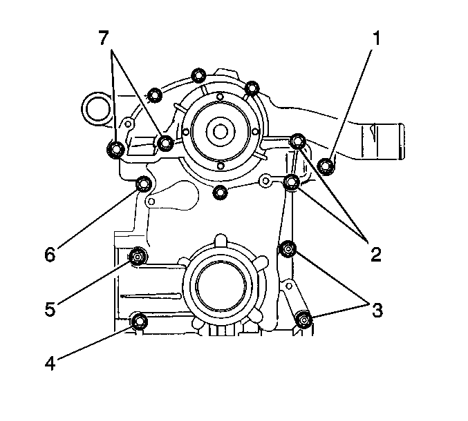
Tighten
Tighten the bolts to 34 N·m (25 lb ft).

Tighten
Tighten the studs to 30 N·m (22 lb ft).
Tighten
Tighten the bolts to 14 N·m (125 lb in).
Tighten
Tighten the sensor to 20 N·m (15 lb ft).

| • | Oil pressure sensor |
| • | Crankshaft position (CKP) sensor |
| • | Camshaft position (CMP) sensor |
Tighten
Tighten the bolts to 13 N·m (116 lb in).
