For 1990-2009 cars only
Tools Required
KM-507-C Ball Joint Remover
Removal Procedure
- Remove the intermediate shaft lower pinch bolt (1).
- Remove the front tire and wheel assemblies. Refer to Tire and Wheel Removal and Installation .
- Complete the following steps on each side of the vehicle:
- If equipped, remove the engine protection shield. Refer to Engine Protection Shield Replacement .
- Remove the front exhaust muffler. Refer to Muffler Replacement .
- Remove the bolt and the nut (1) from the transmission side of the transmission bracket.
- Loosen the bolt (2) on the body side of the transmission bracket.
- Remove the lower bracket bolts (1) and the washer from the steering gear.
- Remove the upper bracket bolts (2) and the washer from the steering gear.
- Move the steering gear toward the passenger side.
- Move the steering gear into the underbody hole on the driver side.
- Remove the steering gear from the vehicle.


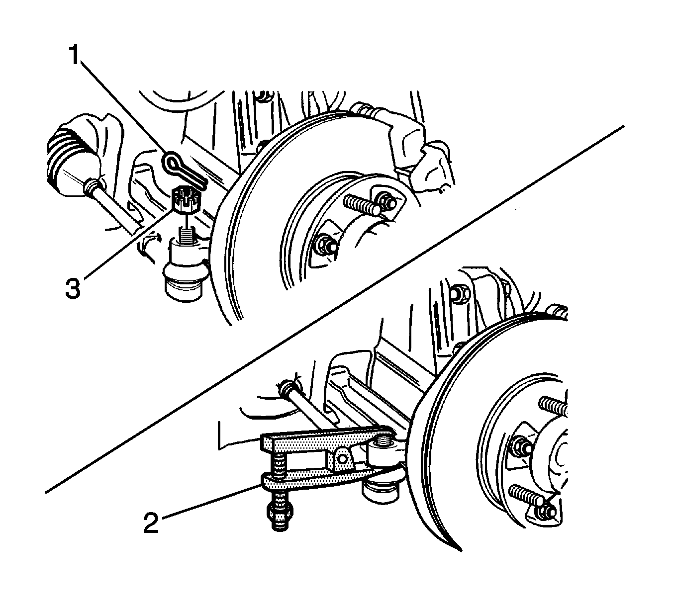
| 3.1. | Remove the cotter pin (1). |
| 3.2. | Remove the nut (3). |
| 3.3. | Use the KM-507-C (2) in order to separate the outer tie rod from the knuckle. |


Installation Procedure
- Install the steering gear with the upper bolts (2) and the washer.
- Install the lower bolts (1) and the washer.
- Install the bolt and the nut (1) to the transmission bracket.
- Install the front exhaust muffler. Refer to Muffler Replacement .
- If equipped, install the engine protection shield. Refer to Engine Protection Shield Replacement .
- Complete the following steps on each side of the vehicle:
- Install the wheels. Refer to Tire and Wheel Removal and Installation .
- Install the intermediate shaft lower pinch bolt (1).
- Inspect the vehicle. Refer to Straight Ahead Inspection .
- Measure the wheel alignment.
- If necessary, adjust the toe. Refer to Front Toe Adjustment .
Notice: Refer to Fastener Notice in the Preface section.

Tighten
Tighten the bolts to 57 N·m (42 lb ft).
Tighten
Tighten the bolts to 57 N·m (42 lb ft).

Tighten
Tighten the nuts and the bolts on the transmission bracket to 80 N·m (59 lb ft).

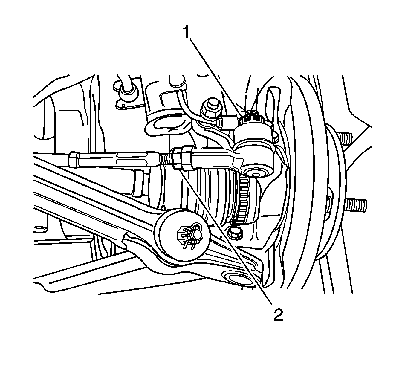
| 6.1. | Install the tie rod to the knuckle. |
| 6.2. | Install the nut (1). |
Tighten
Tighten the nut to 45 N·m (33 lb ft).
| 6.3. | Install the cotter pin. |

Tighten
Tighten the bolt to 25 N·m (18 lb ft).
