Roof Outer Panel Replacement w/ Antennas
Removal Procedure
- Disable the SIR system. Refer to SIR Disabling and Enabling in SIR.
- Disconnect the negative battery cable. Refer to Battery Negative Cable Disconnection and Connection in Engine Electrical.
- Take note of the gap sizes along the perimeter of the roof panel to the headers, the glass, and the doors.
- Remove all related panels and components.
- Repair as much of the damaged area as possible. Refer to Dimensions - Body .
- Note the location and remove the sealers and anti-corrosion materials from the repair area, as necessary. Refer to Anti-Corrosion Treatment and Repair in Paint and Coatings.
- Locate and drill out all he necessary factory welds.
- Use a small flame from an oxy-acetylene torch to aid in releasing the roof panel bond to the structural adhesive.
- Separate the adhesive holding the roof panel to the vehicle. Note the location of the adhesive for installation of the service roof panel.
- Remove the damaged roof panel.
Caution: Refer to Approved Equipment for Collision Repair Caution in the Preface section.
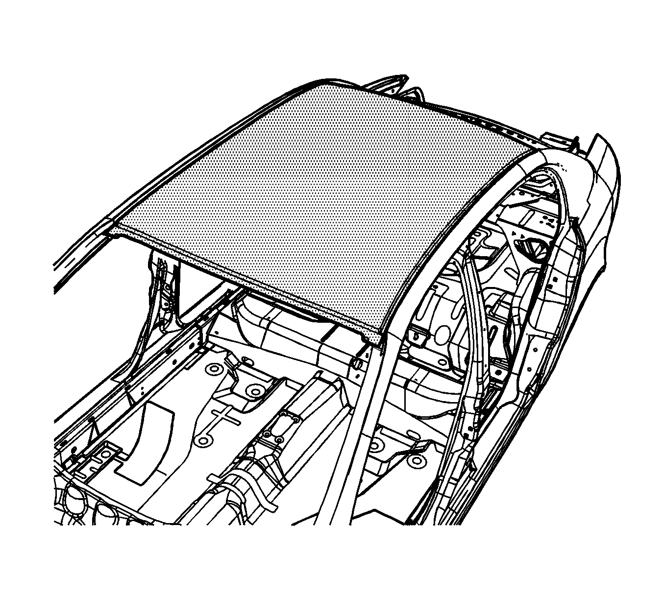
Important: Save the original panel. Measure and note the antenna hole locations.
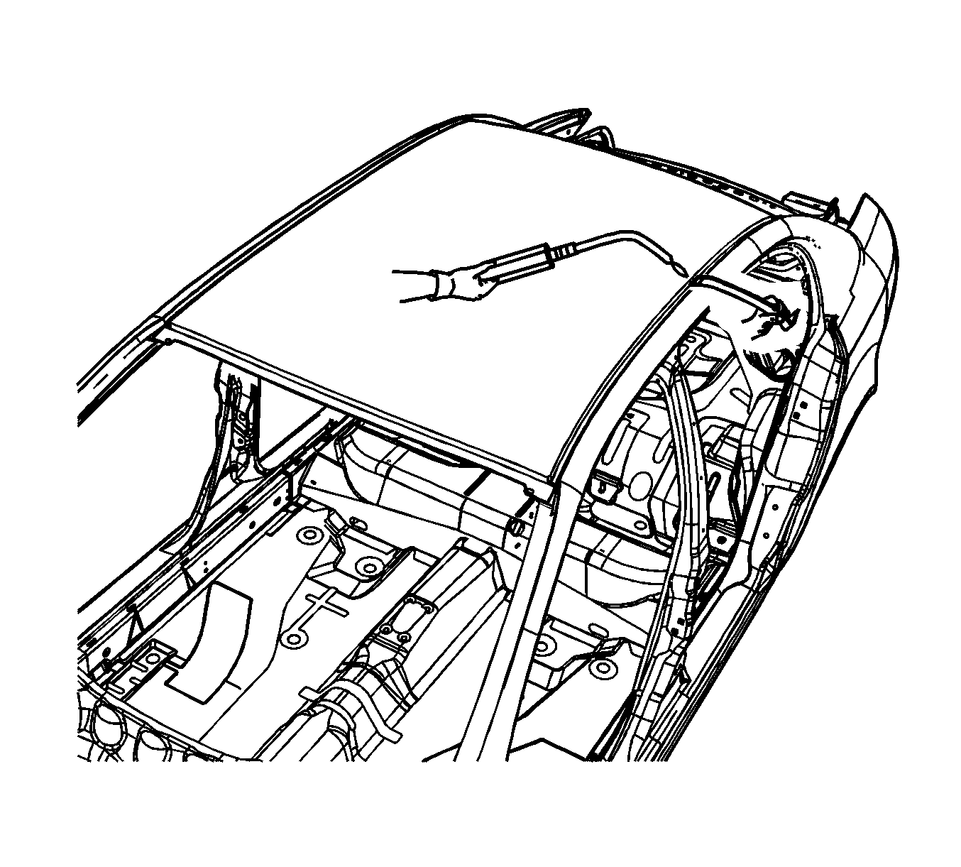
Important: Do not damage any inner panels or reinforcements.
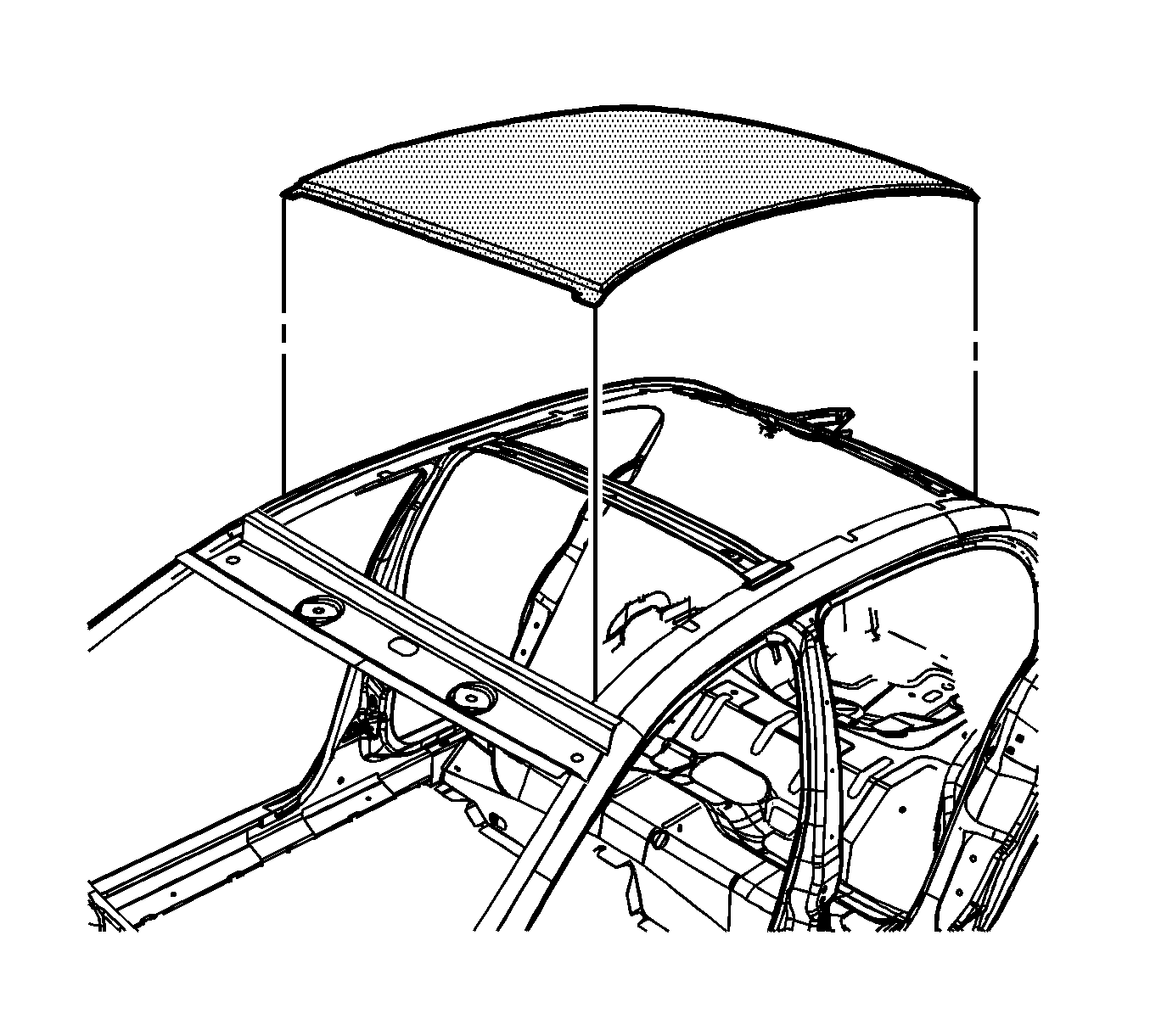
Installation Procedure
- Drill 8-mm (5/16-in) plug weld holes along the front and rear edge of the service part as necessary in the corresponding locations noted on the original panel.
- To locate the center line (1) on the roof panel, measure across the front and rear portion of the panel a short distance in from the front and rear edges of the panel. Mark the center line with a pencil or other non-permanent marking tool.
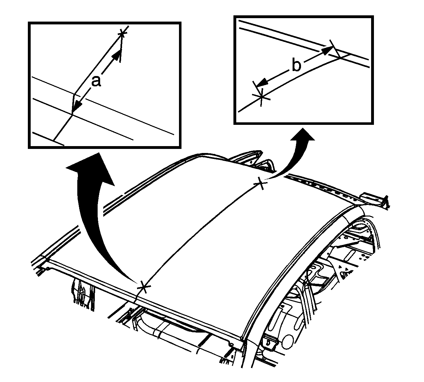
- On the original panel, measure rearward or forward along the center line of the panel to the center of the hole. Note the measurements.
- Measure rearward or forward along the center line of the service panel the distance noted on the original panel. Mark the location with a pencil or other non-permanent marking tool.
- Verify the measurements and the hole configuration.
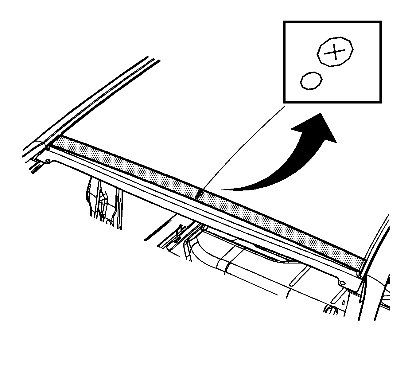
- Drill out the holes from the following steps.
- Grind the surface of the body mating flanges at the same location as the original structural adhesive to bare steel.
- Grind the service panel mating flanges to remove the e-coating. Do not damage the corners or thin the metal during the grinding process.
- Clean the mating surfaces.
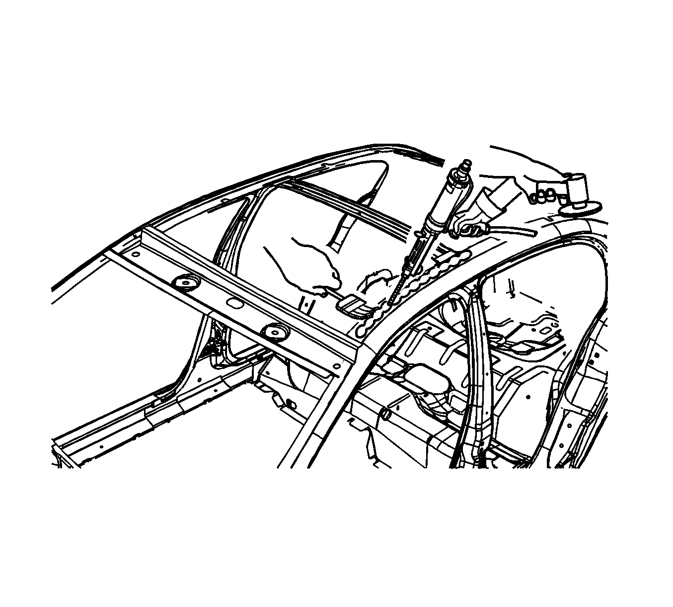
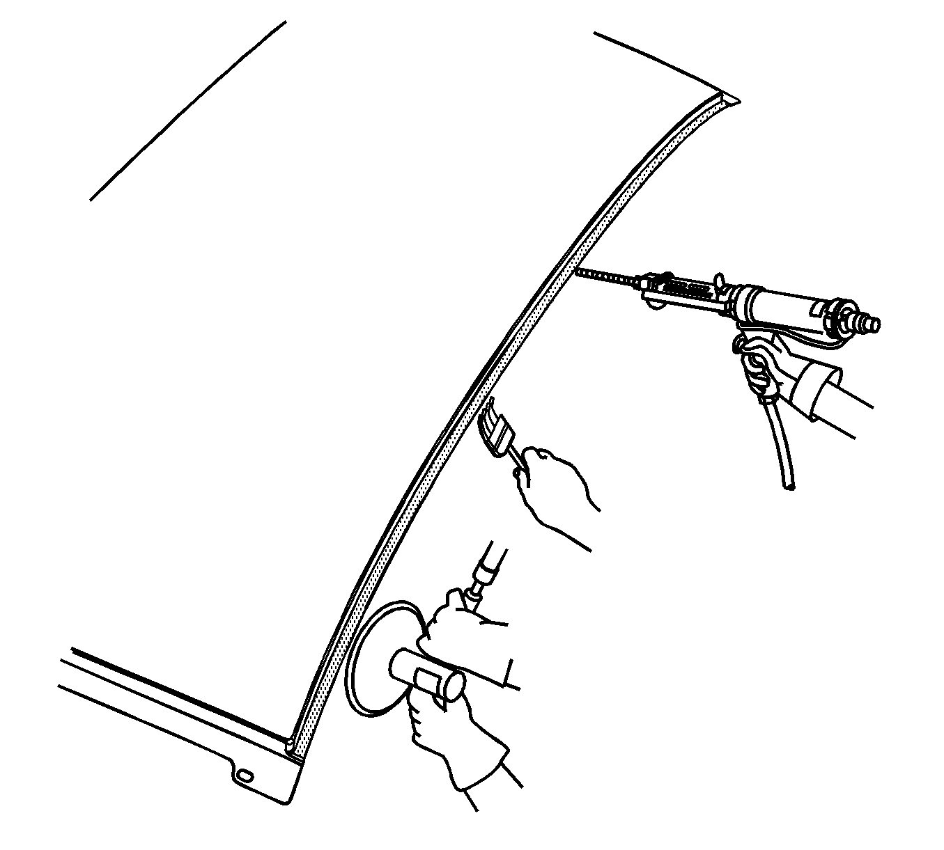
- Apply a bead of metal bonding adhesive to all areas noted earlier as having structural adhesive. Use GM P/N 12378566/7 (Canadian P/N 88901674/5) or equivalent to a thickness of 3-6 mm (1/8-1/4 in) to both mating surfaces.
- Use a small acid brush to spread a coat of adhesive to cover all of the bare metal surfaces to ensure corrosion protection.
- Install the service panel to the vehicle.
- Verify the fit of the roof panel to the front edge of the front header panel and to the rear edge of the rear header panel.
- Verify the fit of the roof panel at the gap along the top of the door frame to the roof panel. Adjust the panel if necessary. Clamp the panel into place.
- Prepare all mating surfaces for welding as necessary
- Apply 3M Weld-Thru Coating P/N 05916 or equivalent to all welded mating surfaces only.
- Use lacquer thinner to remove the excess adhesive from the panel area.
- Allow the adhesive adequate cure time.
- Remove the clamps.
- Plug weld accordingly along the front and rear weld flange.
- Clean and prepare all of the welded surfaces.
- Apply the sealers and anti-corrosion materials to the repair area, as necessary. Refer to Anti-Corrosion Treatment and Repair in Paint and Coatings.
- Paint the repair area. Refer to Basecoat/Clearcoat Paint Systems in Paint and Coatings.
- Install all related panels and components.
- Connect the negative battery cable. Refer to Battery Negative Cable Disconnection and Connection in Engine Electrical.
- Enable the SIR system. Refer to SIR Disabling and Enabling in SIR.
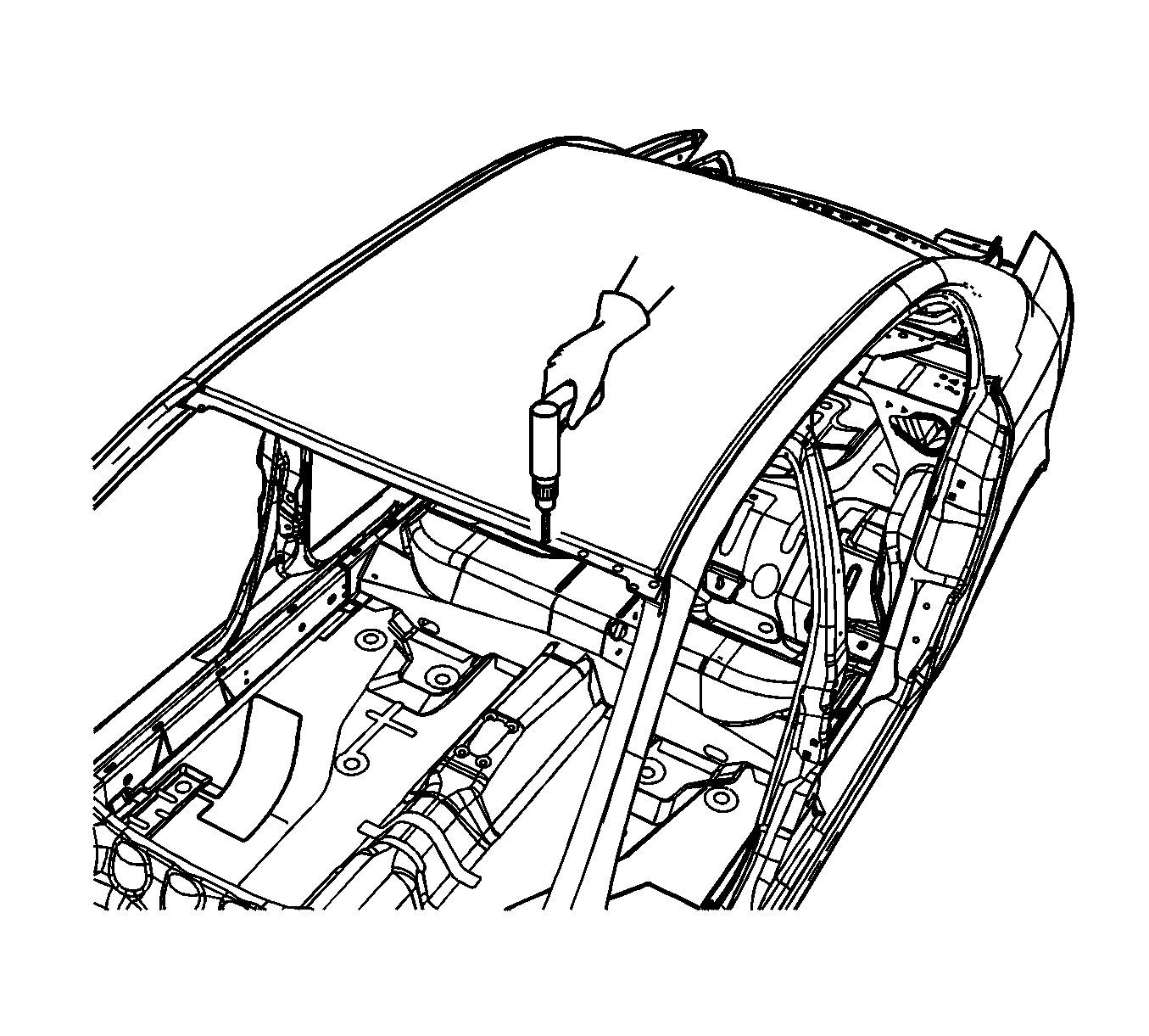
Important: Do not drill holes in the panel along the body side of the roof rail. Use adhesive bond only.
Important: If the location of the original plug weld holes cannot be determined, space the plug weld holes every 40 mm (1½ in) apart.
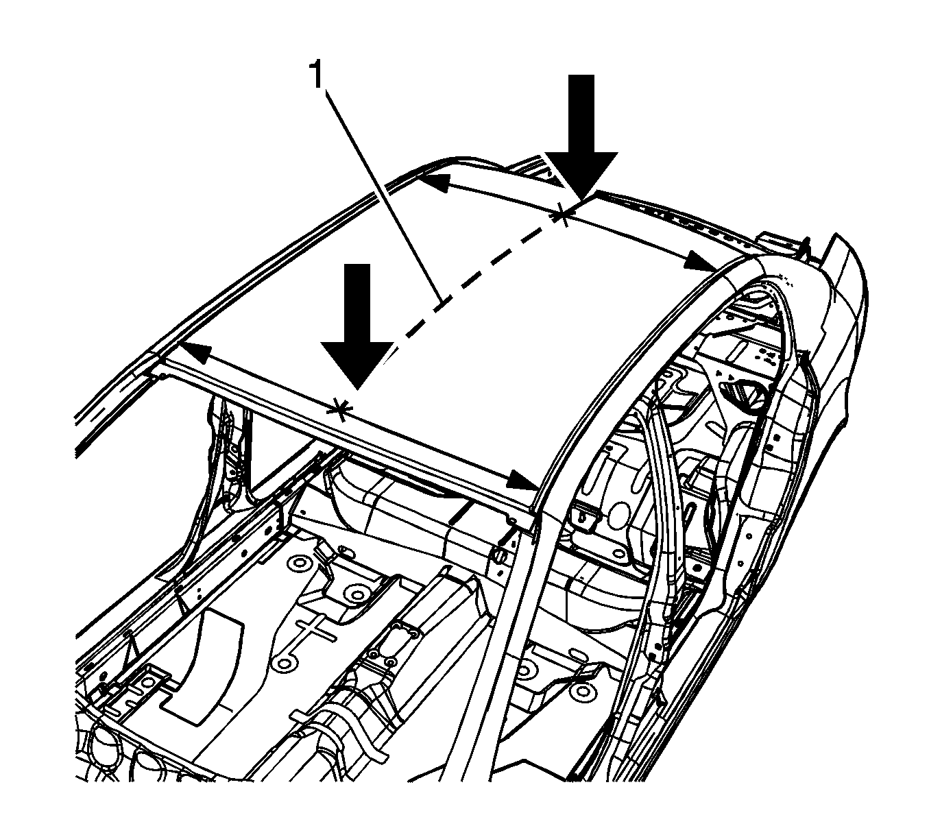
Important: The following steps are for a roof panel that has both the XM radio and OnStar antennas. If the original panel has neither antenna, perform only the steps that are necessary to locate and drill the required hole in the service panel.
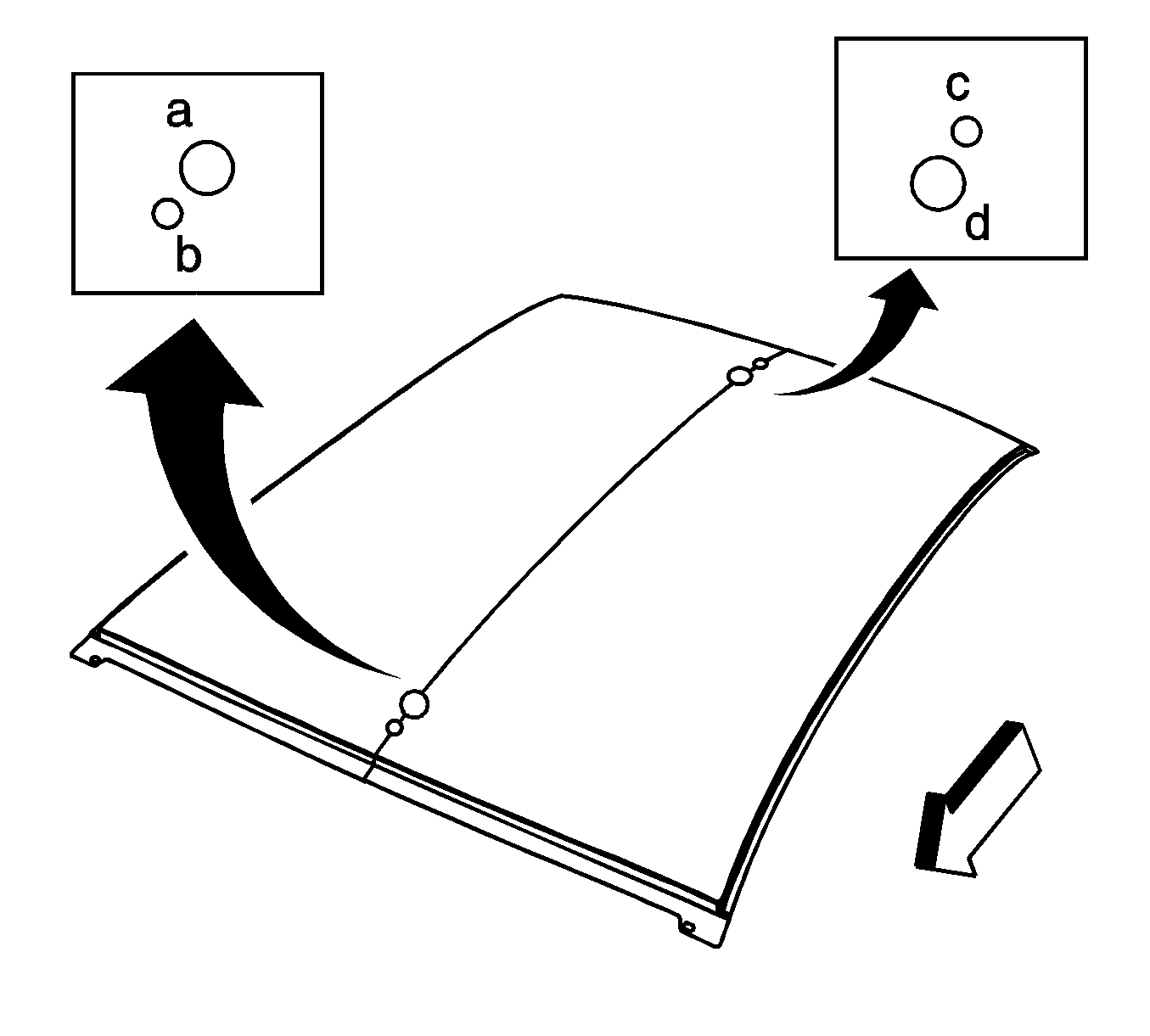
| • | a = 16.5 mm (21/32 in) hole |
| • | b = 5.5 mm (7/32 in) hole |
| • | c = 5.5 mm (7/32 in) hole |
| • | d = 16.5 mm (21/32 in) hole |
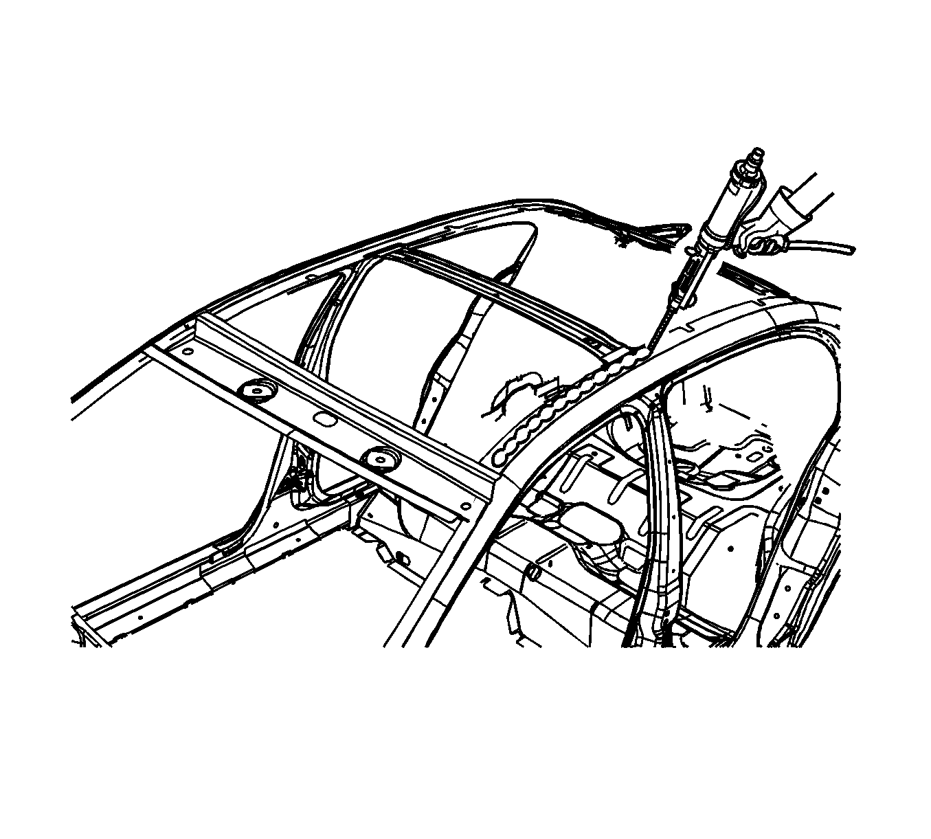
Important: The adhesive has a working time of 40-50 minutes. Do not allow the adhesive to totally cure off the vehicle, as proper alignment of the panel to the body will be difficult.

Important: Do not pull the panels apart after the panels have been joined together. Slide the panels against each other to realign the panels.
Roof Outer Panel Replacement w/o Antennas
Removal Procedure
- Disable the SIR system. Refer to SIR Disabling and Enabling in SIR.
- Disconnect the negative battery cable. Refer to Battery Negative Cable Disconnection and Connection in Engine Electrical.
- Take note of the gap sizes along the perimeter of the roof panel to the headers, the glass, and the doors.
- Remove all related panels and components.
- Repair as much of the damaged area as possible. Refer to Dimensions - Body .
- Note the location and remove the sealers and anti-corrosion materials from the repair area, as necessary. Refer to Anti-Corrosion Treatment and Repair in Paint and Coatings.
- Locate and drill out all he necessary factory welds.
- Use a small flame from an oxy-acetylene torch to aid in releasing the roof panel bond to the structural adhesive.
- Separate the adhesive holding the roof panel to the vehicle. Note the location of the adhesive for installation of the service roof panel.
- Remove the damaged roof panel.
Caution: Refer to Approved Equipment for Collision Repair Caution in the Preface section.


Important: Do not damage any inner panels or reinforcements.

Installation Procedure
- Drill 8-mm (5/16-in) plug weld holes along the front and rear edge of the service part as necessary in the corresponding locations noted on the original panel.
- Grind the surface of the body mating flanges at the same location as the original structural adhesive to bare steel.
- Grind the service panel mating flanges to remove the e-coating. Do not damage the corners or thin the metal during the grinding process.
- Clean the mating surfaces.
- Apply a bead of metal bonding adhesive to all areas noted earlier as having structural adhesive. Use GM P/N 12378566/7 (Canadian P/N 88901674/5) or equivalent to a thickness of 3-6 mm (1/8-1/4 in) to both mating surfaces
- Use a small acid brush to spread a coat of adhesive to cover all of the bare metal surfaces to ensure corrosion protection.
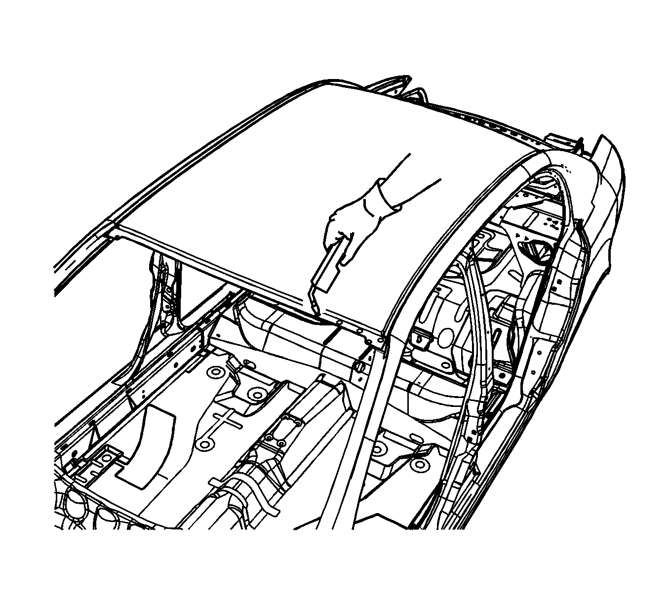
- Install the service panel to the vehicle.
- Verify the fit of the roof panel to the front edge of the front header panel and to the rear edge of the rear header panel.
- Verify the fit of the roof panel at the gap along the top of the door frame to the roof panel. Adjust the panel if necessary. Clamp the panel into place.
- Prepare all mating surfaces for welding as necessary.
- Apply 3M Weld-Thru Coating P/N 05916 or equivalent to all welded mating surfaces only.
- Use lacquer thinner to remove the excess adhesive from the panel area.
- Allow the adhesive adequate cure time.
- Remove the clamps.
- Plug weld accordingly along the front and rear weld flange.
- Clean and prepare all of the welded surfaces.
- Apply the sealers and anti-corrosion materials to the repair area, as necessary. Refer to Anti-Corrosion Treatment and Repair in Paint and Coatings.
- Paint the repair area. Refer to Basecoat/Clearcoat Paint Systems in Paint and Coatings.
- Install all related panels and components.
- Connect the negative battery cable. Refer to Battery Negative Cable Disconnection and Connection in Engine Electrical.
- Enable the SIR system. Refer to SIR Disabling and Enabling in SIR.

Important: Do not drill holes in the panel along the body side of the roof rail. Use adhesive bond only.
Important: If the location of the original plug weld holes cannot be determined, space the plug weld holes every 40 mm (1½ in) apart.


Important: The adhesive has a working time of 40-50 minutes. Do not allow the adhesive to totally cure off the vehicle, as proper alignment of the panel to the body will be difficult.

Important: Do not pull the panels apart after the panels have been joined together. Slide the panels against each other to realign the panels.

