For 1990-2009 cars only
Removal Procedure
Caution: Refer to Approved Equipment for Collision Repair Caution in the Preface section.
- Disable the SIR system. Refer to SIR Disabling and Enabling.
- Disconnect the negative battery cable. Refer to Battery Negative Cable Disconnection and Connection.
- Remove all related panels and components.
- Note the location and remove the sealers and anti-corrosion materials from the repair area. Refer to Anti-Corrosion Treatment and Repair.
- Repair as much of the damage as possible to the factory specifications.
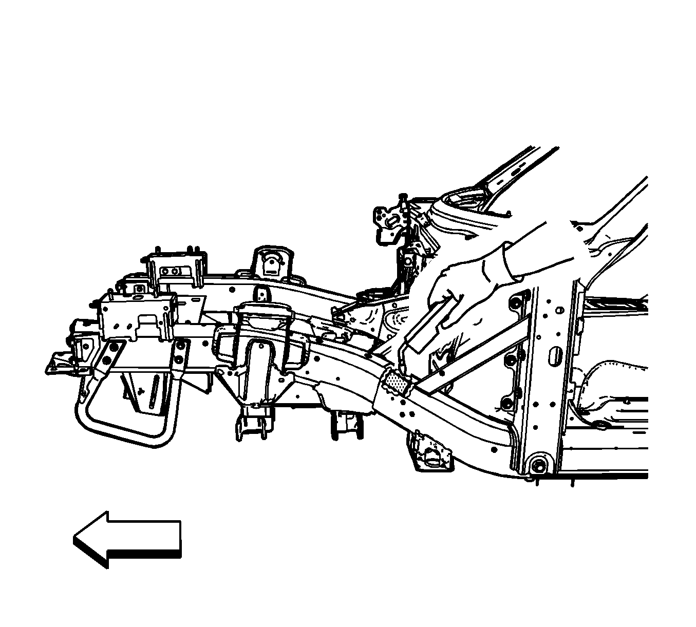
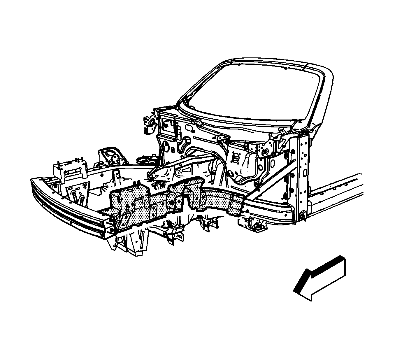
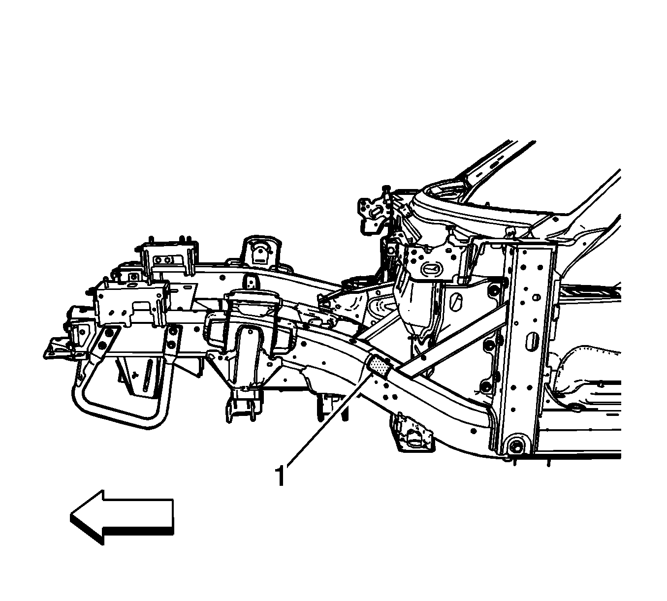
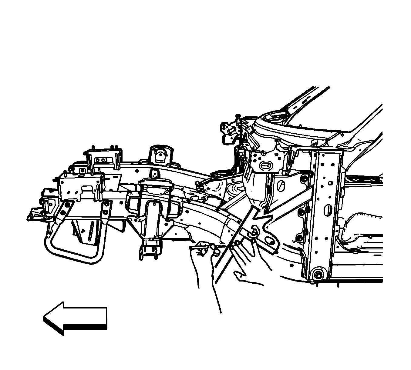
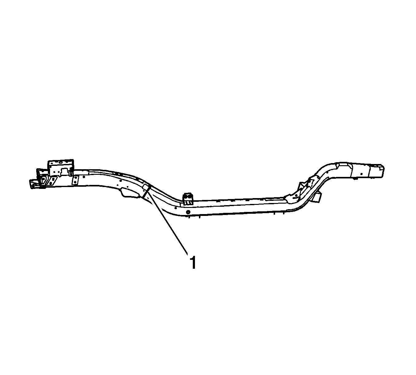
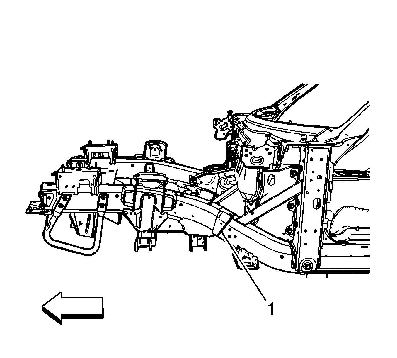
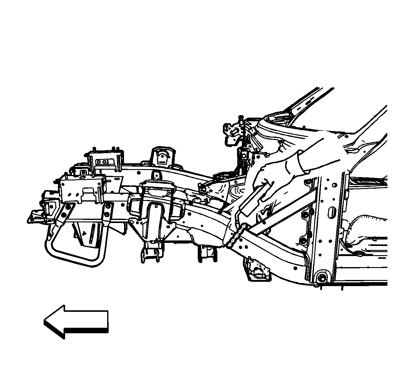
- Remove the shaded section (1) of the steel plate.
- Determine the sectioning joint location within the recommended area (1).
- Determine the sectioning joint location.
- Mark the top of the frame rail at the sectioning location.
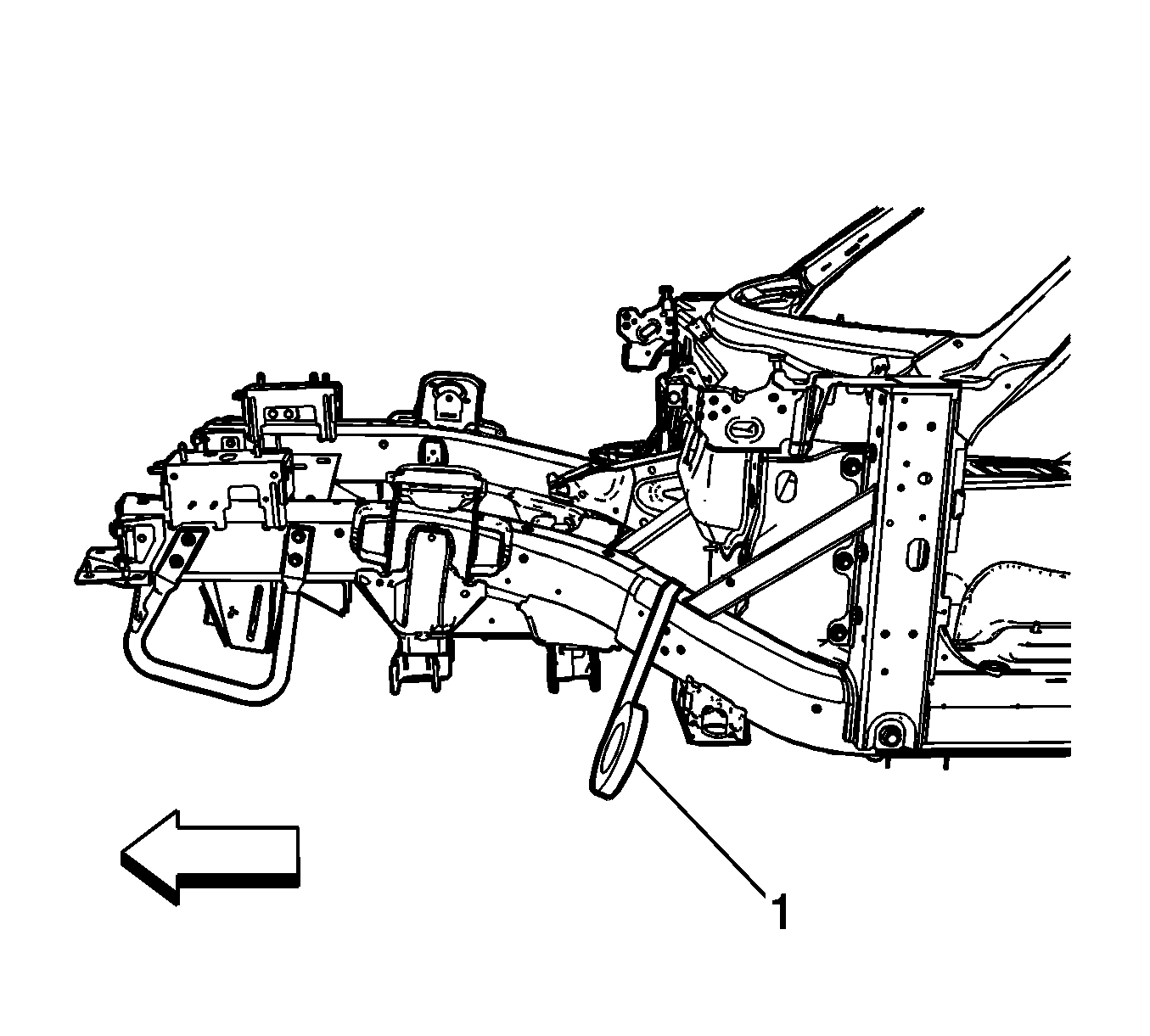
- At the mark, align a sliding square (1) or similar tool square to the surface of the vertical walls of the frame rail.
- Scribe a line to both sides of the frame rail.
- Apply masking tape to the scribe line. Apply the tape completely around the frame rail.
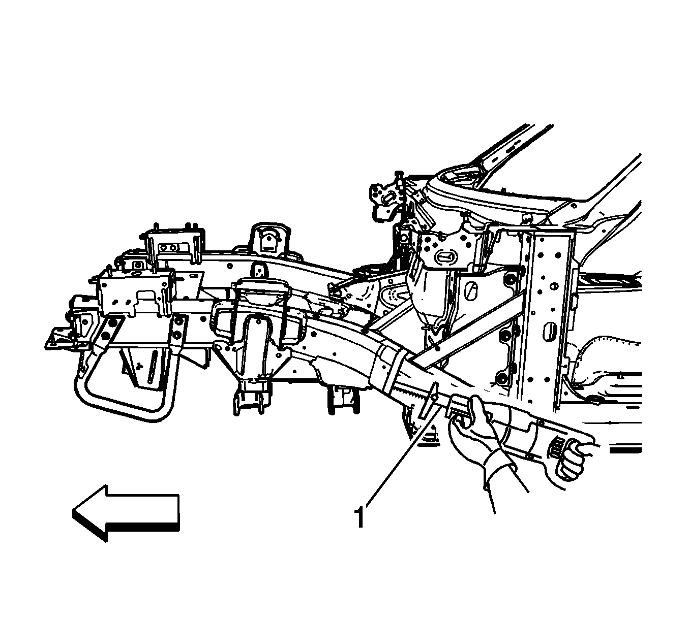
- Use a reciprocating saw or equivalent tool to cut the frame rail at the rear edge of the tape line.
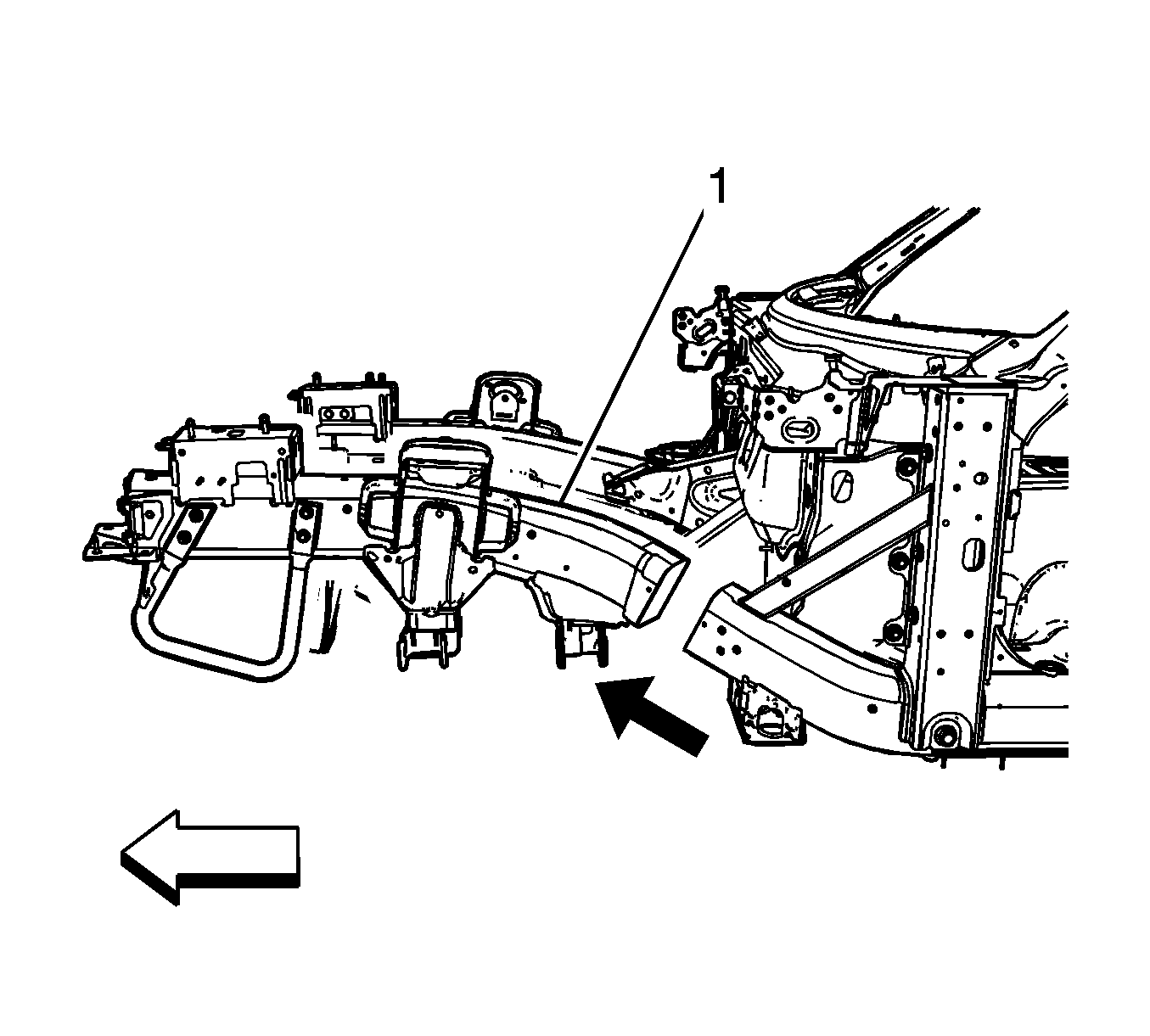
- Remove the damaged frame rail front section.
Caution: Refer to Collision Sectioning Caution in the Preface section.
Important: Save the cut-out piece of steel plate.
Installation Procedure
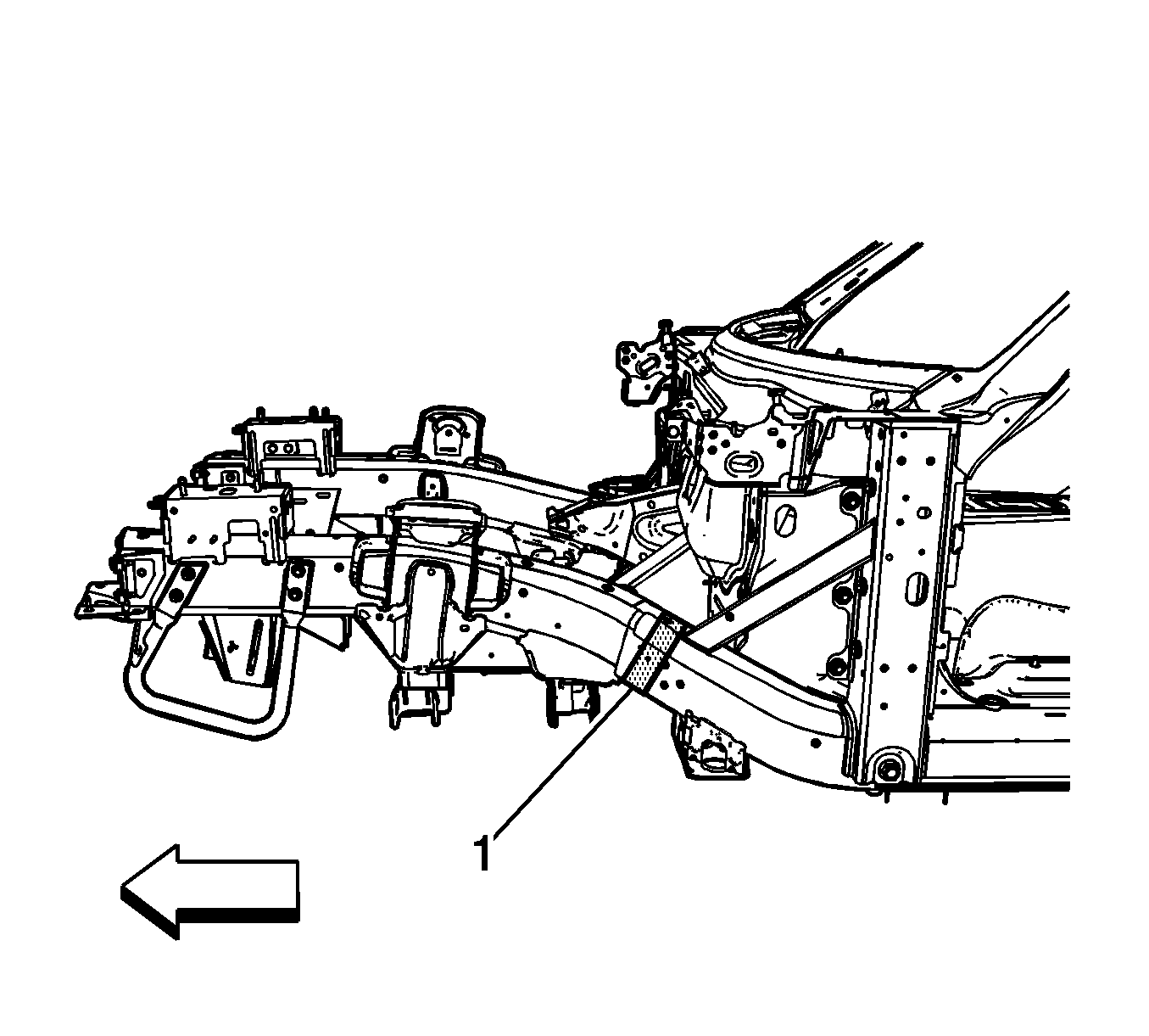
- Determine the sectioning joint location (1) from the new frame rail assembly.
- Cut the new frame rail front section.
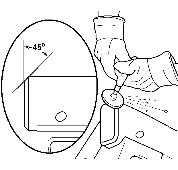
- Grind the existing frame rail sectioning location to a 45 degree angle.
- Clean and prepare all of the welded mating surfaces.
- Apply GM-approved weld-thru coating or equivalent to all mating surfaces. Refer to Anti-Corrosion Treatment and Repair.
- Make a 50-mm (2-in) weld backer sleeve. Refer to Sleeved Butt Joint Repair.
- Position the service frame section (1) to the existing frame.
- Maintain a gap of 1 1/2 times the frame rail metal thickness at the sectioning joint. Clamp in place.
- Inspect the frame measurements 3-dimensional to ensure proper position in the service frame.
- Using a metal-inert gas (MIG) welder, weld completely around the sleeve joint.
- Using a MIG welder, weld the saved cut-out steel plate to the frame rail.
- Apply the sealers and anti-corrosion materials to the repair area. Refer to Anti-Corrosion Treatment and Repair.
- Paint the repair area. Refer to Basecoat/Clearcoat Paint Systems.
- Install all related panels and components.
- Connect the negative battery cable. Refer to Battery Negative Cable Disconnection and Connection.
- Enable the SIR system. Refer to SIR Disabling and Enabling.
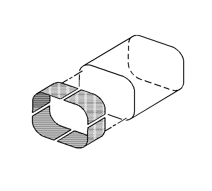
Important: Install the sleeve to the existing frame rail.
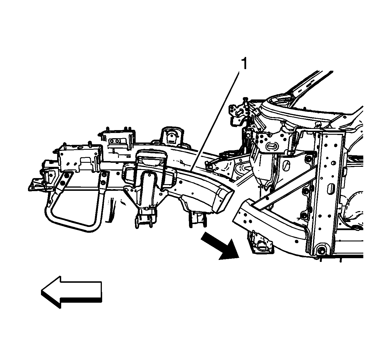
Important: Use a 25 mm (1 in) stitch weld for minimal heat distortion.
