CAMPAIGN:THROTTLE CABLE MAY FREEZE (CANADA ONLY)

SUBJECT: HIGH EFFORT OR BINDING ACCELERATOR CONTROL CABLES (CANADA ONLY)
Models: 1993-94 Pontiac Sunbird Models (Built at Ramos Arizpe) Equipped With 4-Cylinder Engines (RPO LE4) and Cruise Control (RPO K34)
TO: ALL GENERAL MOTORS DEALERS
IMPORTANT
THIS IS A DIFFERENT AND SEPARATE CAMPAIGN FROM CAMPAIGN 3D23 WHICH IS CURRENTLY UNDERWAY. CAMPAIGN 3D23 MUST STILL BE COMPLETED.
THE VEHICLES INVOLVED IN THIS CAMPAIGN WERE BUILT AFTER THE VEHICLES INVOLVED IN THE CAMPAIGN 3D23 (SEE VIN RANGE). IT HAS BEEN DETERMINED THAT SOME VEHICLES INVOLVED IN THIS CAMPAIGN WERE MANUFACTURED USING A PROCESS THAT COULD ALLOW WATER TO ENTER THE ACCELERATOR CABLE HOUSING. THIS WATER COULD FREEZE IN COLD TEMPERATURES, RESULTING IN A BINDING/STICKING ACCELERATOR CONTROL CABLE.
General Motors of Canada Limited has determined that a defect which relates to motor vehicle safety exists in certain 1993-94 Pontiac Sunbird Models. The accelerator control cable on some vehicles may develop a high effort and/or binding condition at temperatures below freezing.
Water may have entered the cable conduit during vehicle manufacture. At temperatures below freezing, ice may form in the cable conduit, resulting in high accelerator pedal effort or binding of the accelerator control cable. If the accelerator control cable requires high effort or binds, loss of normal throttle control may result, or the throttle may not return to idle when the accelerator pedal is released. If this were to occur while the vehicle was in motion, a vehicle crash could occur without prior warning.
To prevent this condition from occurring, dealers are to replace the accelerator control cable assembly.
VEHICLES INVOLVED:
Involved are certain 1993-94 Pontiac Sunbird model vehicles built within the following VIN breakpoints:
Year Model Plant Plant Code From Through
1993 Pontiac Sunbird Ramos Arizpe "S" PS834829 PS842859 1994 Pontiac Sunbird Ramos Arizpe "S" RS800016 RS831058
NOTE: PLEASE CHECK DCS SCREEN 45 OR YOUR V.I.N. LISTING BEFORE PERFORMING CAMPAIGN TO ENSURE THAT THE VEHICLE IS AFFECTED. ONLY AFFECTED VIN'S WILL BE PAID.
All affected vehicles have been identified by the VIN listing provided to involved dealers with this bulletin. Any dealer not receiving a listing was not shipped any of the affected vehicles.
DEALER CAMPAIGN RESPONSIBILITY:
All unsold new vehicles in dealer's possession and subject to this campaign must be held and inspected/repaired per the Service Procedure of this Campaign Bulletin before owners take possession of these vehicles.
Dealers are to perform this campaign on all involved vehicles at no charge to owners, regardless of kilometers traveled, age of vehicle, or ownership, from this time forward.
Owners of vehicles recently sold from your new vehicle inventory with no owner information indicated on the dealer listing, are to be contacted by the dealer, and arrangements made to make the required correction according to instructions contained in this bulletin. This could be done by mailing to such owners a copy of the owner letter accompanying this bulletin. Campaign follow-up cards should not be used for this purpose, since the owner may not as yet have received the notification letter.
In summary, whenever a vehicle subject to this campaign is taken into your new or used vehicle inventory, or is in your dealership for service in the future, please take the steps necessary to be sure the campaign correction has been made before selling or releasing the vehicle.
CAMPAIGN PROCEDURE:
Refer to Section 4 of the Service Policies and Procedures Manual for the detailed procedure on handling Product Campaigns. Dealers are requested to complete the campaign on all transfers as soon as possible.
OWNER NOTIFICATION:
All owners of record at the time of campaign release are shown on the attached computer listing and have been notified by first class mail from General Motors (see copy of owner letter included with this bulletin). The listings provided are for campaign activity only and should not be used for any other purpose.
PARTS INFORMATION:
Parts required to complete this campaign should be ordered through regular channels, as follows:
Part Number Description Quantity/Vehicle ----------- ----------- ---------------- 22593227 Cable Assembly - Accelerator Control 1 With Cruise Control (RPO K34)
PARTS AND LABOUR CLAIM INFORMATION:
Credit for the campaign work performed will be paid upon receipt of a properly completed campaign claim card or DCS transmission in accordance with the following:
Repair Code Description Time Allowance ----------- ----------- -------------- 2A Replace Accelerator Cable With Cruise Control .6
Time allowance includes 0.1 hour for dealer administrative detail associated with this campaign. Parts credit will be based on dealer net plus 30% to cover parts handling.
SERVICE PROCEDURE:
1. Open hood and support using hood support rod.
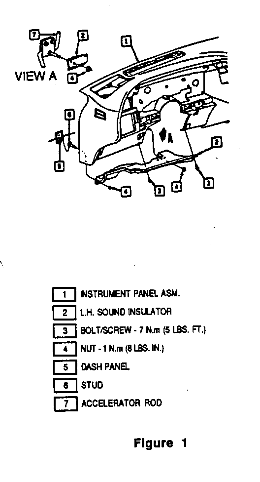
2. Remove two screws and two nuts from the left side lower sound insulator panel. Disconnect the courtesy lamp connector and remove the sound insulator panel. See figure 1.
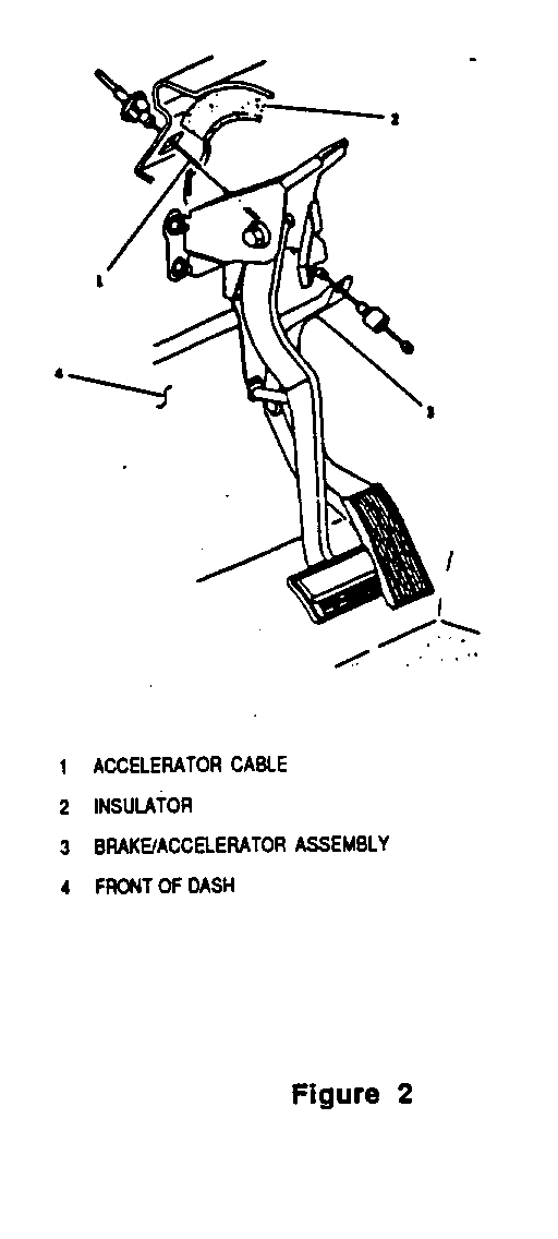
3. Release the accelerator cable retainer from the accelerator pedal lever assembly. See figure 2.
4. Depress the accelerator cable locking tabs and carefully push the cable housing forward through the cowl toward the engine compartment.
5. Observe the routing of the cruise control cable from the accelerator control bracket to the cruise control servo bracket Make sure that the routing and positioning of the replacement cable matches that of the original cable.
6. Disengage the accelerator control cable cross slug from the throttle body pulley/cam. Disengage the cruise control servo cable from the throttle body lever by removing the cable retaining clip.
7. Depress the accelerator/cruise control cable locking tabs and disengage the cable assembly from the engine accelerator control cable bracket.
8. Disengage the cruise control servo cable from the servo by removing the cable retaining clip. Depress the cruise control cable locking tabs and disengage the cruise control cable from the cruise control servo bracket.
9. Remove the old cable assembly from the vehicle.
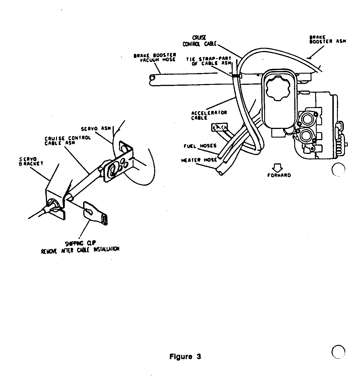
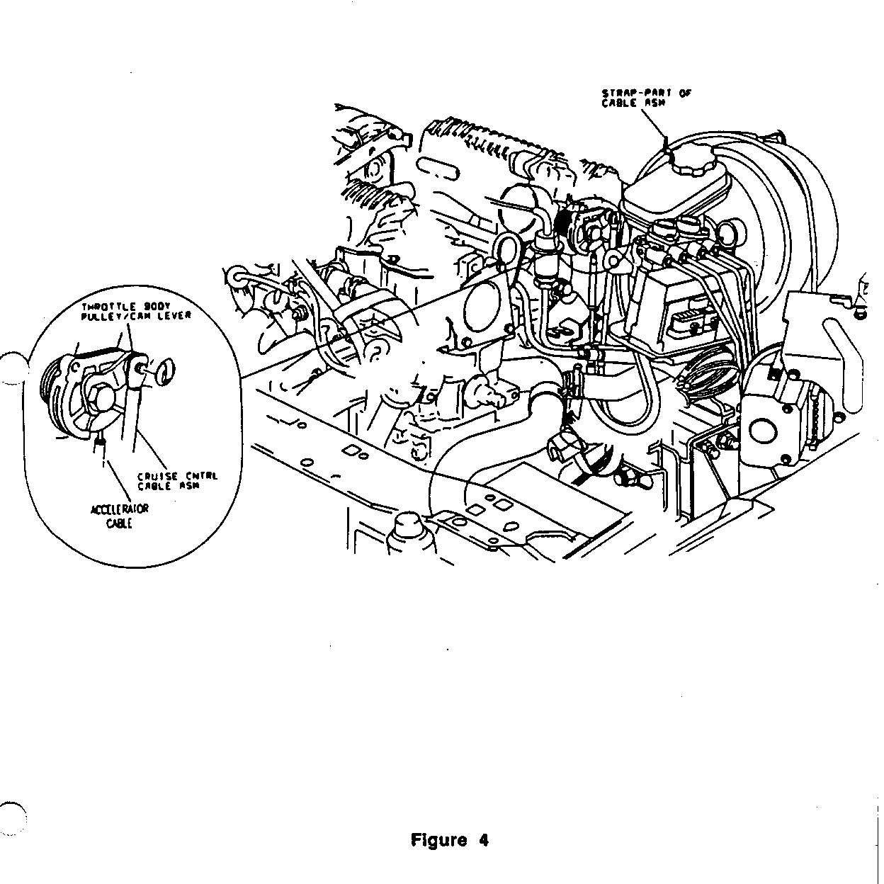
10. Position the new accelerator control cable assembly to the engine accelerator control cable bracket, partially routing the accelerator cable under the fuel feed and return pipes and the heater hose. See figures 3 and 4.
11. Attach the accelerator control cable assembly to the accelerator control cable bracket by pushing the cable fitting into the bracket until the locking tabs are fully engaged in the bracket
12. Slide the accelerator control cable cross slug into the throttle body pulley/cam, and properly position the cable in the pulley/cam channel.
13. Position the fitting end of the cruise control servo cable to the throttle body lever stud and secure by installing the cable retaining clip.
14. From the accelerator control cable bracket, route the accelerator control cable under the fuel feed and return pipes/hoses and the heater hose, inboard of the brake master cylinder and brake booster assembly, and through the accelerator cable opening in the cowl. See figures 3 and 4. On vehicles equipped with automatic transmission, the accelerator cable should be routed between the brake master cylinder and the transaxle fluid fill tube.
15. Make sure that the cable housing is not kinked, twisted, or damaged in any way. Secure the accelerator control cable assembly to the cowl by pushing the cable fitting into the cowl opening until the locking tabs are fully engaged.
16. Position the accelerator control cable in the slot in the accelerator pedal lever assembly, and install the plastic cable retainer to the accelerator pedal lever. Make sure the cable retainer is fully seated in the accelerator pedal lever.
17. Check for proper, unrestricted operation of the throttle linkage. The linkage must operate freely between idle and full wide open throttle.
18. Route the cruise control cable inboard of and over the top of the brake vacuum booster to the cruise control servo bracket.
19. Attach the cruise control cable to the cruise control servo bracket by pushing the cable fitting into the bracket until the locking tabs are fully engaged in the bracket. Make sure that the cruise control cable is not twisted, kinked, or damaged in any way.
20. Adjust the cruise control cable, and secure the cable to the servo assembly using the following procedure:
A. Both ends of the cable must be completely engaged in their brackets, and the cruise control cable must be attached to the throttle body lever stud with the retainer installed.
B. Pull the servo end of the cruise control cable toward the servo without moving the throttle body lever.
C. If one of the six (6) holes in the servo assembly tab lines up with the cable pin, connect the pin to the tab and secure by installing the cable retaining clip.
D. If a tab hole does not line up with the cable pin, move the cable away from the servo assembly until the next closest tab hole lines up with the cable pin. Connect the pin to the tab and secure by installing the cable retaining clip. See figure 3.
IMPORTANT: DO NOT STRETCH THE CRUISE CONTROL CABLE TO MAKE A PARTICULAR TAB HOLE CONNECT TO THE CRUISE CONTROL CABLE PIN. THIS WILL PREVENT THE ENGINE FROM RETURNING TO IDLE.
21. After the cruise control cable is completely installed, remove the shipping clip from the end of the cable near the servo. See figure 3.
22. Check for proper operation of the throttle and cruise control linkages. The linkages must operate freely between the idle and full wide open throttle positions.
23. Reconnect the courtesy lamp and reinstall the left side sound insulator panel.
24. Install Campaign Identification Label.
INSTALLATION OF CAMPAIGN IDENTIFICATION LABEL
Clean surface of radiator upper mounting panel and apply a Campaign Identification Label. Make sure the correct campaign number is inserted on the label. This will indicate that the campaign has been completed.
Dear General Motor Customer
General Motors of Canada Limited has determined that a defect which relates to motor vehicle safety exists in certain 1993-94 Pontiac Sunbird Models. The accelerator control cable on some vehicles may develop a high effort and/or binding condition at temperatures below freezing.
Water may have entered the cable conduit during vehicle manufacture. At temperatures below freezing, ice may form in the cable conduit, resulting in high accelerator pedal effort or binding of the accelerator control cable. If the accelerator control cable requires high effort or binds, loss of normal throttle control may result, or the throttle may not return to idle when the accelerator pedal is released. If this were to occur while the vehicle was in motion, a vehicle crash could occur without prior warning.
To prevent this condition from occurring, your dealer will replace the accelerator control cable assembly.
This service will be provided for you at no charge.
Please contact your GM dealer as soon as possible to arrange a service date.
If parts are required, ask your dealer for details regarding their availability. If parts are not in stock, they can be ordered before scheduling your service date.
This letter identifies your vehicle. Presentation of this letter to your dealer will assist their Service personnel in completing the necessary correction to your vehicle in the shortest possible time.
We are sorry to cause you this inconvenience; however, we have taken this action in die interest of your continued satisfaction with our products.
Customer Support Department General Motors of Canada Limited


General Motors bulletins are intended for use by professional technicians, not a "do-it-yourselfer". They are written to inform those technicians of conditions that may occur on some vehicles, or to provide information that could assist in the proper service of a vehicle. Properly trained technicians have the equipment, tools, safety instructions and know-how to do a job properly and safely. If a condition is described, do not assume that the bulletin applies to your vehicle, or that your vehicle will have that condition. See a General Motors dealer servicing your brand of General Motors vehicle for information on whether your vehicle may benefit from the information.
