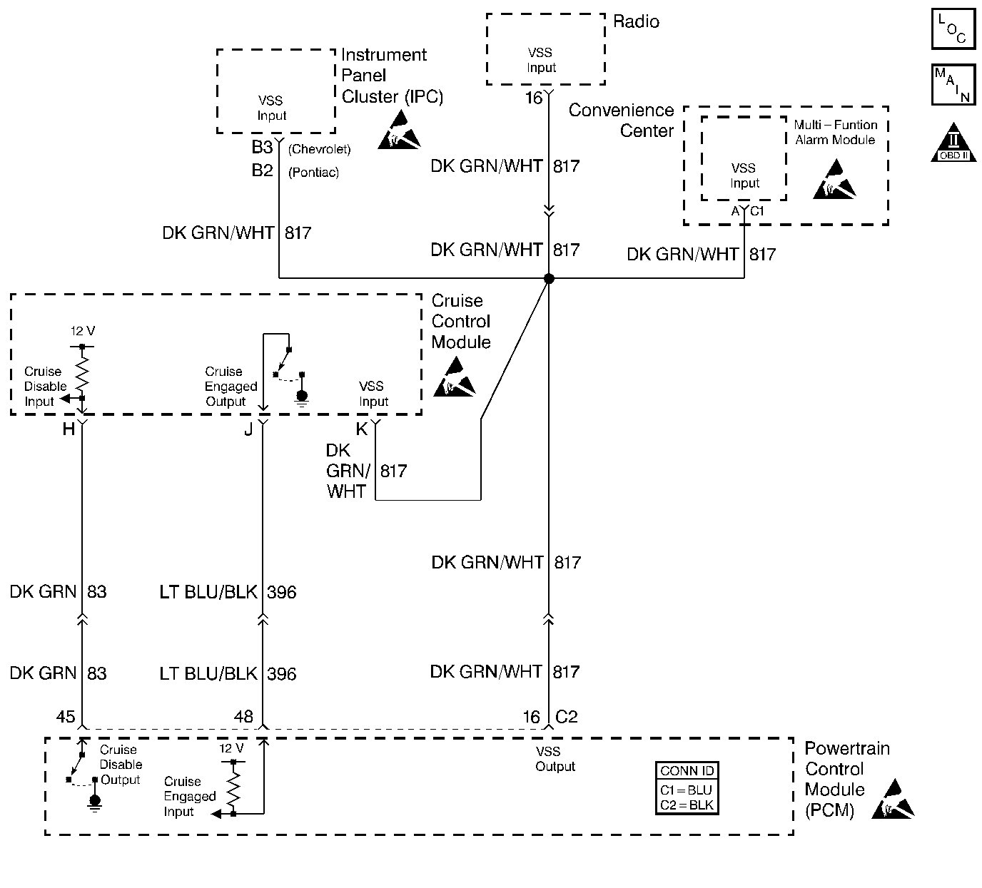
Diagnosis
The following table will diagnose the cruise disable and cruise engaged circuits. Refer to Wiring Repairs in Wiring Systems when diagnosing the remaining cruise control system circuits.
Circuit Description
The stepper motor cruise module communicates with the powertrain control module (PCM) over three circuits (cruise engaged, cruise disabled and VSS output). The cruise enable status tells the PCM if the cruise control system is enabled. The vehicle speed sensor (VSS) output is the speed signal from the vehicle speed sensor through the PCM and used by the cruise control module. The cruise disable line allows the PCM to disable cruise under the various conditions described below:
| • | DTCs P0122, P0123, P0200, P0335, P0502, P0562, P0563 are not set. |
| • | Engine is not running. |
| • | Transmission is in Park, Neutral, or Reverse (automatic transmission). |
| • | Transmission is out of gear (manual transmission). |
| • | Safety fuel cut-off is active. |
| If the PCM detects any one of the above conditions, it will interrupt the ground at the cruise disable input circuit and disable the cruise control. |
Diagnostic Aids
| • | This table will not diagnose any cruise control system circuits other than those connected to the PCM. For diagnosis of the remaining circuits, refer to Wiring Repairs in Wiring Systems. |
| • | An Intermittent problem may be caused by: |
| • | A poor connection |
| • | Rubbed through wire insulation |
| • | A wire that is broken inside the insulation |
| • | The cruise control system may disable if actual speed is less than 24 km/h (15 mph) than commanded vehicle speed, i.e. towing a trailer, or climbing a steep grade. |
| • | Minimum vehicle speed for setting the cruise control system is 40 km/h (25 mph). |
Test Description
Number(s) below refer to the step number(s) on the Diagnostic Table.
-
The Powertrain OBD System Check prompts the technician to complete some basic checks and store the freeze frame and failure records data on the scan tool if applicable. This creates an electronic copy of the data taken when the malfunction occurred. The information is then stored on the scan tool for later reference.
-
The cruise speed set has to be above the minimum speed (25 mph/40 km/h) required for cruise operation. Drive the vehicle in an area where enough room is allowed for using the cruise control.
-
If the vehicle was in the enabling criteria for cruise operation, the PCM should have read cruise Engaged even if cruise was not requested. The Cruise Engaged circuit provides a ground to the cruise control module. This step checks for an open or shorted cruise engage circuit.
-
The replacement PCM must be programmed and the crankshaft position system variation procedure must be preformed. Refer to the latest Techline procedure for PCM reprogramming and also refer to the Crankshaft Position System Variation Procedure.
Step | Action | Value(s) | Yes | No |
Did you perform the Powertrain On-Board Diagnostic (OBD) System Check? | -- | Go to Powertrain On Board Diagnostic (OBD) System Check 2.4L or Powertrain On Board Diagnostic (OBD) System Check 2.2L | ||
2 |
Are any DTCs present? | -- | Go to appropriate DTC Diagnostic | |
Does the cruise control operate normally? | 40 Km/h (25 MPH) | |||
Observe the Cruise (Engage/Disengaged) parameter on the scan tool. Does the Cruise parameter display engaged? | -- | |||
5 |
Does the Cruise (Engage/Disengaged) parameter display a change with each action? | -- | ||
6 |
Does the DMM display a voltage near the specified value? | B+ | ||
7 |
Does the test light illuminate? | -- | ||
8 |
Does the test light illuminate? | -- | ||
9 |
Does the DMM display a voltage near the specified value? | B+ | ||
10 |
Does the test light turn ON and OFF with each command of the scan tool? | -- | ||
11 | Did the test light stay illuminated in step 10? | -- | ||
12 |
Does the test light illuminate? | -- | ||
13 |
Was a repair necessary? | -- | ||
14 |
Was a repair necessary? | -- | ||
15 |
Was a repair necessary? | -- | ||
16 |
Was a repair necessary? | -- | ||
17 |
Was a repair necessary? | -- | ||
18 |
Was a repair necessary? | -- | ||
19 |
Was a repair necessary? | -- | ||
20 |
Was a repair necessary? | -- | ||
21 |
Is the action complete? | -- | -- | |
Is the action complete? | -- | -- | ||
23 | Operate the vehicle within the conditions under which the original symptom was observed. Does the system now operate properly? | -- | System OK |
