Removal Procedure
Tools Required
| • | J 8049 Brake
Spring Remover and Installer |
| • | J 29840 Brake
Spring Remover and Installer |

- Raise and support the
vehicle. Refer to
Lifting and Jacking the Vehicle
in General Information.
Important:
| • | Mark the relationship of the wheel to the axle flange in order
to ensure proper wheel balance upon assembly. |
| • | Mark the relationship of the brake drum to the axle flange in
order to ensure proper wheel balance upon assembly. |
- Remove the tire and wheel assembly. Refer to
Tire and Wheel Removal and Installation
in Tires and Wheels.
- Remove the brake drum. If removing the brake drum is difficult,
perform the following steps:
| • | Ensure that the parking brake is released. |
| • | Back off the parking brake adjustment cable. |
| • | Use a rubber mallet in order to tap gently on the outer rim of
the drum and/or around the inner drum diameter by the spindle. Do not use
excessive force, which may deform the drum. |
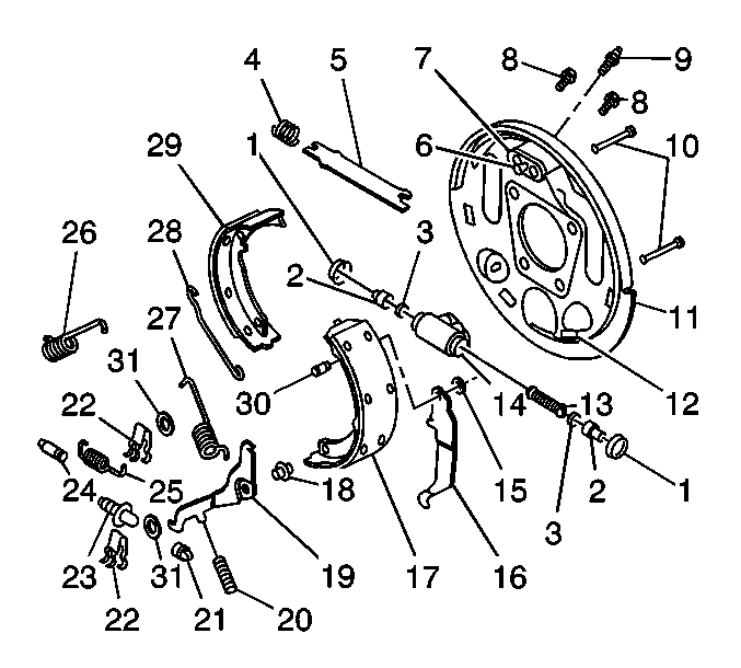
- Remove the return springs (26, 27) using J 8049
or J 29840
.
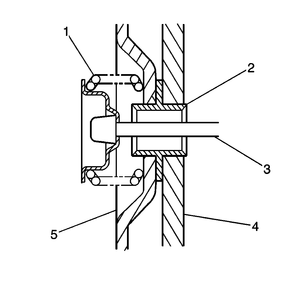
- Remove the hold-down springs (22) and the pins (10)
using suitable pliers.
- Remove the actuator link (28) while lifting up on the actuator
lever (19).
- Remove the following components:
| 7.1. | The actuator lever (19) |
| 7.2. | The lever return spring (20) |
| 7.3. | The bearing sleeve (18) |
- Remove the parking brake strut (5) and the strut spring (4).
- Disconnect the parking brake cable.
- Remove the shoe and lining assemblies (29, 17).
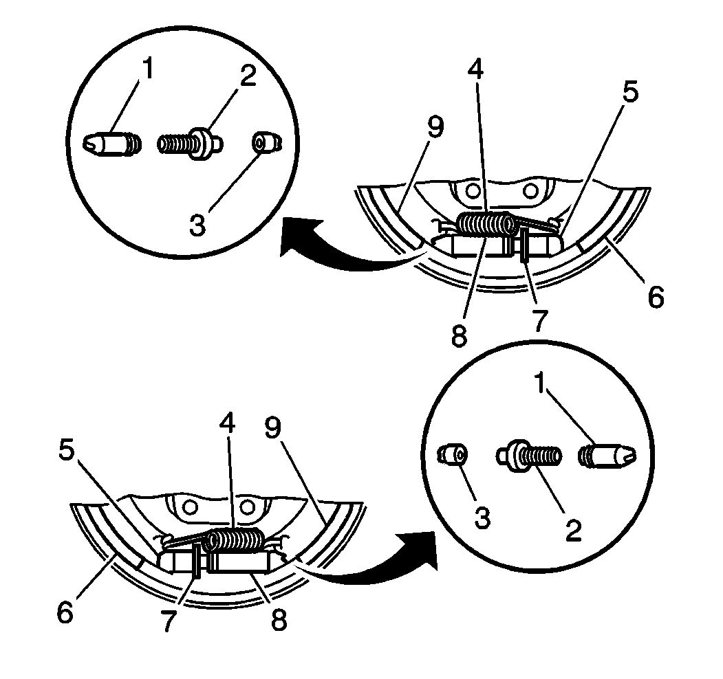
- Remove the adjusting screw assembly (21, 23, 24).
- Remove the following components:
| 12.3. | The parking brake lever |
- Remove the retaining ring (15), the pin (30), and
the parking brake lever (16) from the secondary shoe (17). If
any parts are of doubtful strength or quality due to discoloration from heat,
overstress, or wear, replace the parts.
Cleaning and Inspection Procedure

- Perform the following
actions on the components before you reinstall the adjusting screw assembly (21,
23, 24):
- Clean the threads on the adjusting screw (23) with a wire
brush.
- Wash all components in clean denatured alcohol.
- Apply brake lubricant GM P/N 1052196 or equivalent to the
threads of the following components:
| • | The adjusting screw (23) |
| • | The inside diameter of the socket (21) |
- You have obtained an adequate supply of lubricant when a continuous
bead of lubricant appears at the open end of the pivot nut (24) and
the socket (21) after you have fully engaged the threads.
- Lubricate the 6 pads (12) where the brake shoes contact
the backing plate.
- Inspect the threads of the adjusting screw (23) for smooth
rotation over the full length of the screw.
Installation Procedure

- Install the parking brake
lever (16) into the secondary shoe (17) with the pin (30)
and the retaining ring (15).

- Install the adjusting
screw assembly (1, 2, 3) and the adjusting screw spring (4).

- Attach the parking brake
cable.
- Install the shoe and lining assemblies (17, 29).
- Install the parking brake strut (5) and the strut spring (4),
by spreading the shoes (17, 29) apart. Verify that the shoes are positioned
correctly:
| • | The end without the strut spring (4) should engage the
parking brake lever (16) and the secondary shoe and lining (17). |
| • | The end with the strut spring (4) should engage the primary
shoe and lining (29). |

Important: Install the bearing sleeve (18) between the secondary shoe and
lining (17) and the actuator lever (19).
- Install the following components:
| 6.1. | The bearing sleeve (18) |
| 6.2. | The actuator lever (19) |
| 6.3. | The lever return spring (20) |

- Install the hold-down
pins (10) and the hold-down springs (22).
- Install the actuator link (28) on the anchor pin (19)
while you hold up on the lever.
- Install the shoe return springs (26, 27) using J 8057
.
- Adjust the brakes. Refer to
Drum Brake Adjustment
- Install the brake drum. Align the previous marks.
- Install the tire and wheel assembly. Refer to
Tire and Wheel Removal and Installation
in Tires
and Wheels.
- Remove the safety stands. Lower the vehicle.


