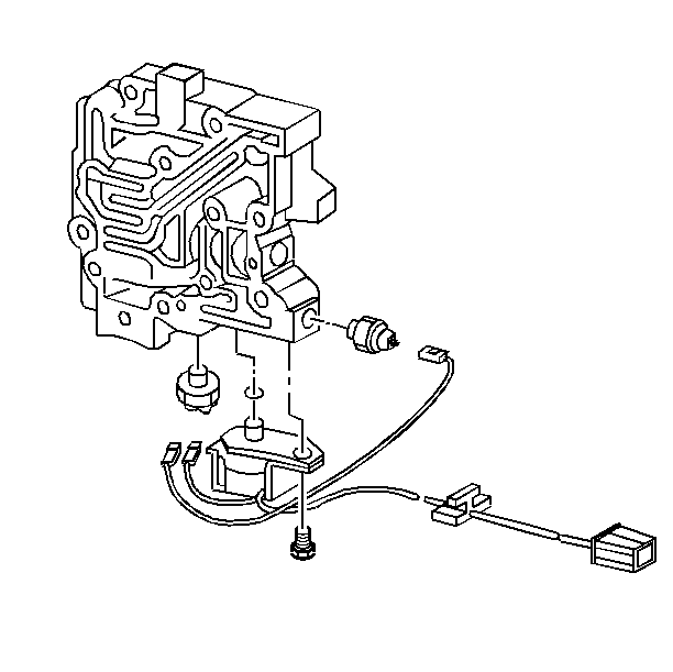
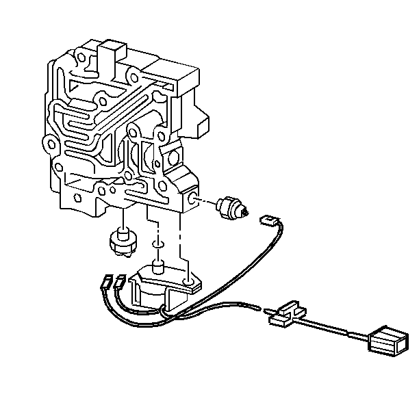
Removal Procedure
- Disconnect the negative battery cable. Refer to
Caution: Unless directed otherwise, the ignition and start switch must be in the OFF or LOCK position, and all electrical loads must be OFF before servicing any electrical component. Disconnect the negative battery cable to prevent an electrical spark should a tool or equipment come in contact with an exposed electrical terminal. Failure to follow these precautions may result in personal injury and/or damage to the vehicle or its components.
in General Information. - Remove the TV cable from the transmission. Refer to Automatic Transmission Throttle Valve Cable Replacement .
- Remove the transmission mount bracket.
- Remove the valve body cover. Refer to Valve Body Cover Replacement .
- Remove the bolt that secures the TCC solenoid to the valve body.
- Remove the TCC solenoid.
- Remove the TCC solenoid wiring connector from the case connector.
- Disconnect the TCC wires from the pressure switches.
- Remove the TV lever bolts from the control valve body.
- Remove the TV lever.
- Remove the TV cable link.
- Remove the remaining bolts that secure the valve body to the case cover.
- Remove the valve body from the case cover.
- Remove the green bolt.
- Separate the valve body from the oil pump assembly.
- Remove the check ball behind the control valve assembly.


Important: Do not lose the six check balls. Do not remove the green bolt.


Important: If any service is required on the valve body and/or oil pump, refer to 3T40 Unit Repair Manual.
Installation Procedure
Tools Required
J 36850 Transjel™ Transmission Assembly Lubricant
- Install the check ball behind the oil pump assembly.
- Install the control valve body to the oil pump assembly.
- Install the check ball in the valve body.
- Install the green bolt. If necessary, use J 36850 , or equivalent, in order to hold in place.
- Install the valve body to the case cover.
- Install the valve body to case cover bolts.
- Install the TV lever.
- Install the TV cable link.
- Install the TV lever bolts to the control valve body.
- Connect the TCC wires and the wiring connectors.
- Install the TCC solenoid.
- Install the TCC solenoid bolt to the valve body.
- Install the valve body cover with a new gasket. Refer to Valve Body Cover Replacement .
- Install the transmission mount bracket.
- Install the TV cable to the transmission. Refer to Automatic Transmission Throttle Valve Cable Replacement .
- Connect the negative battery cable.
- Adjust the TV cable. Refer to TV Cable Adjustment .
- Check the oil level.

Notice: Use J 36850 or equivalent during assembly in order to retain checkballs or to lubricate components. Lubricants other than the recommended assembly lube changes the transmission fluid characteristics and causes undesirable shift conditions or filter clogging.


