Tools Required
| • | J 29840 Brake Spring
Remover and Installer |
| • | J 8049 Brake Spring
Remover and Installer |
Caution: Refer to Brake Dust Caution in the Preface section.
Removal Procedure

- Raise and support the vehicle. Refer to
Lifting and Jacking the Vehicle
in General Information.
- Remove the tire and wheel assembly. Refer to
Tire and Wheel Removal and Installation
in Tires and Wheels.
- Matchmark the position of the brake drum to the wheel studs.
- Remove the brake drum.
- Using the J 8049
, or
the J 29840
, remove the brake
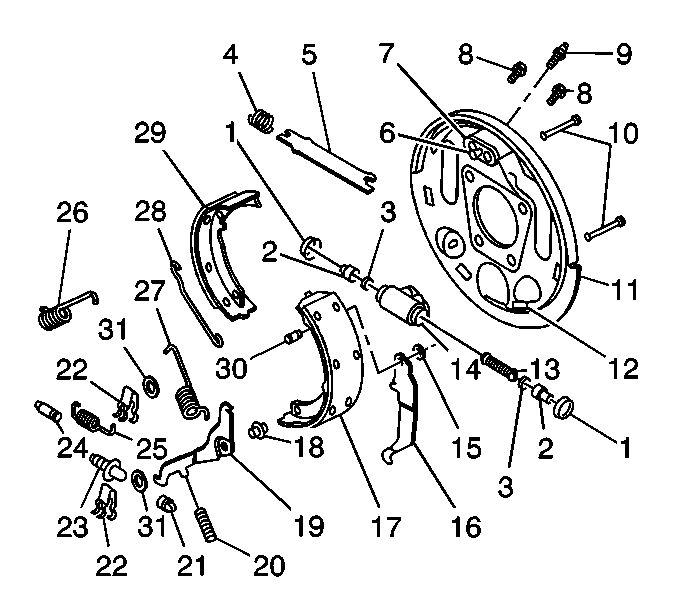
shoe return springs (26, 27).
- Remove the hold-down springs (22) and hold-down pins (10).
- Release the actuator link (28) from the actuator lever (19),
while pressing down on the lever.
- Remove the actuator link (28).
- Remove the actuator lever (19), the lever return spring (20),
and the actuator lever sleeve (18) from the secondary brake shoe (17).
- Remove the park brake strut (5) and the strut spring (4),
while spreading the shoes (17, 29) apart.
- Disconnect the park brake cable from the park brake lever (16).
- Remove the shoe and lining assemblies (17, 29).
- Remove the adjusting screw assembly (21, 23, 24) and the adjusting
screw spring (25) from the brake shoes (17, 29).
- Remove the park brake lever retaining ring (15), the park brake
lever (16), and the pivot pin (30) from the secondary shoe (17).
- Inspect all parts for discoloration due to heat, or stress. Replace parts
as necessary.
- Replace all worn parts.
Installation Procedure

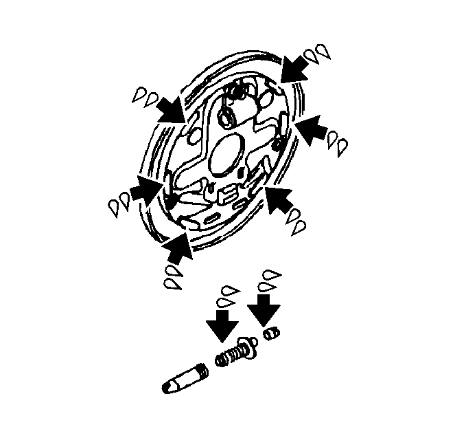
- Lubricate the brake shoe backing plate on the 6
brake shoe contact areas, with high temperature silicone brake lubricant.
- Lubricate the adjusting screw threads, socket, and socket face with a
thin coat of high temperature silicone brake lubricant. Inspect the threads of the
adjusting screw for smooth rotation over the full length of the screw.

- Install the park brake lever pivot pin (30),
the park brake lever (16), and the retaining ring (15) to the secondary
shoe (17).

Important:
| • | Do NOT interchange the right and left adjusting screw assemblies. |
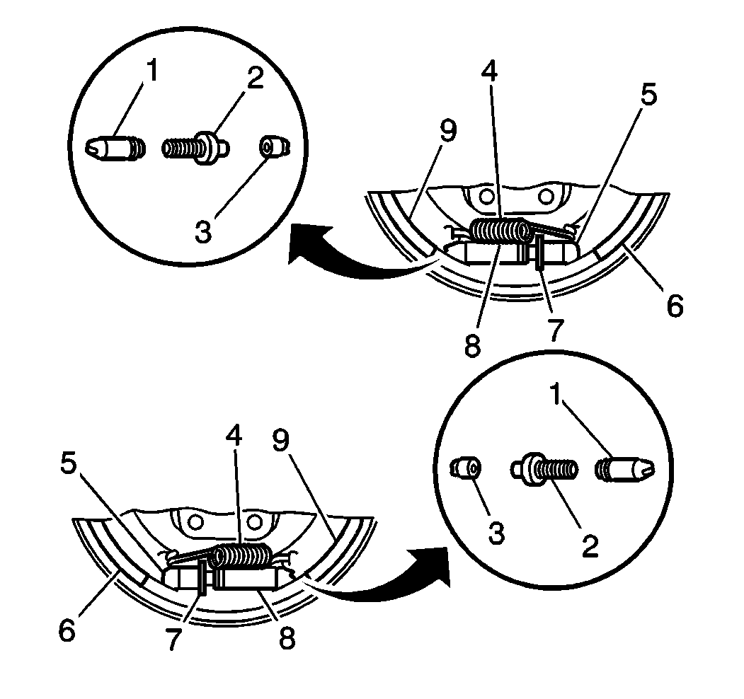
| • | Ensure that the star wheel (7) on the adjusting screw assembly
does not contact the coils of the adjusting screw spring (4). |
- Install the adjusting screw assembly (1, 2, 3) and the adjusting screw
spring (4) to the brake shoes.

- Attach the park brake cable to the park
brake lever (16).
- Install the shoe and lining assemblies (17, 29).
- Install the park brake strut (5) and the strut spring (4),
while spreading the shoes (17, 29) apart. Verify that the shoes are positioned
correctly to the strut:
| • | The end of the park brake strut (5) without the strut spring (4)
should engage the parking brake lever (16) and the secondary shoe and lining (17). |
| • | The end of the strut (5) with the strut spring (4) should
engage the primary shoe and lining (29). |

- Install the actuator lever sleeve (2), the actuator lever (5),
and the lever return spring, to the secondary brake shoe (4).
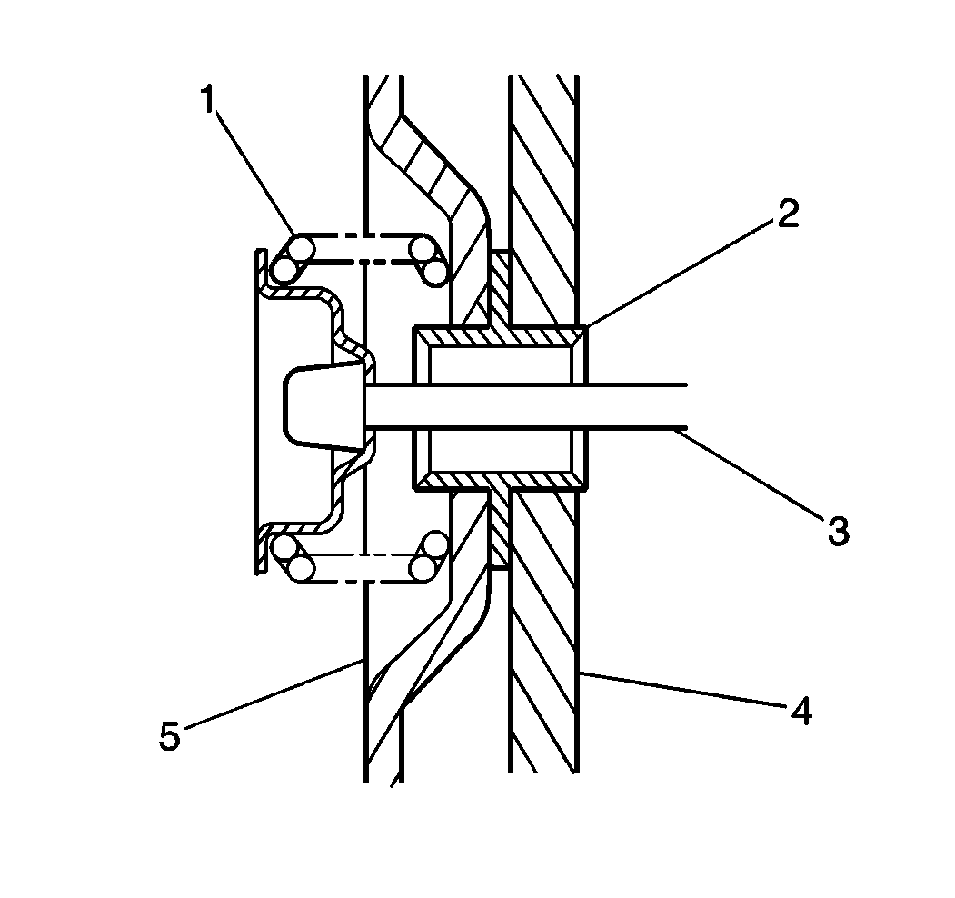
- Install the hold-down pins (3) and hold-down springs (1).

- Install the actuator link (28).
- Secure the actuator link (28) to the actuator lever (19),
while pressing down on the lever.
- Using the J 8049
, or
the J 29840
, install the brake
shoe return springs (26, 27).
- Adjust the drum brakes. Refer to
Drum Brake Adjustment
.
- Install the brake drum. Use the matchmark made prior to removal for proper
orientation to the flange.
- Install the tire and wheel assembly. Refer to
Tire and Wheel Removal and Installation
in Tires and Wheels.
- Lower the vehicle.


