Caution: Refer to Brake Fluid Irritant Caution in the Preface section.
Notice: Refer to Brake Fluid Effects on Paint and Electrical Components Notice in the Preface section.
Notice: Always connect or disconnect the wiring harness connector from the EBCM/EBTCM with the ignition switch in the OFF position. Failure to observe this precaution could result in damage to the EBCM/EBTCM.
Removal Procedure
- Turn the ignition switch to the OFF position.
- Clean the brake pressure modulator valve (BPMV) pipe fitting areas of any accumulated dirt and foreign material.
- Clean the electronic brake control module (EBCM) to brake pressure modulator valve (BPMV) area of any accumulated dirt and foreign material.
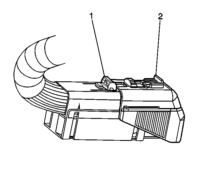
- Disengage the electrical connector position assurance (CPA) locking tab (1) from the connector sliding cover lock tab.
- Depress the cover lock tab, then move the sliding connector cover (2) to the open position.
- Disconnect the electrical connector from the EBCM.
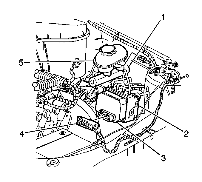
- Disconnect the caliper and wheel cylinder brake pipes (2) from the BPMV.
- Cap the brake pipe ends to prevent brake fluid loss and contamination.
- Plug the brake pipe ports on the BPMV to prevent fluid loss and contamination.
- Carefully reposition the caliper and wheel cylinder brake pipes (2) to gain access to the master cylinder pipes (1).
- Disconnect the master cylinder brake pipes (1) from the BPMV.
- Cap the brake pipe ends to prevent brake fluid loss and contamination.
- Plug the brake pipe ports on the BPMV to prevent fluid loss and contamination.
- Remove the EBCM/BPMV assembly to mounting bracket bolt.
- Remove the EBCM/BPMV assembly from the vehicle.
- Remove the 4 EBCM-to-BPMV retaining bolts.
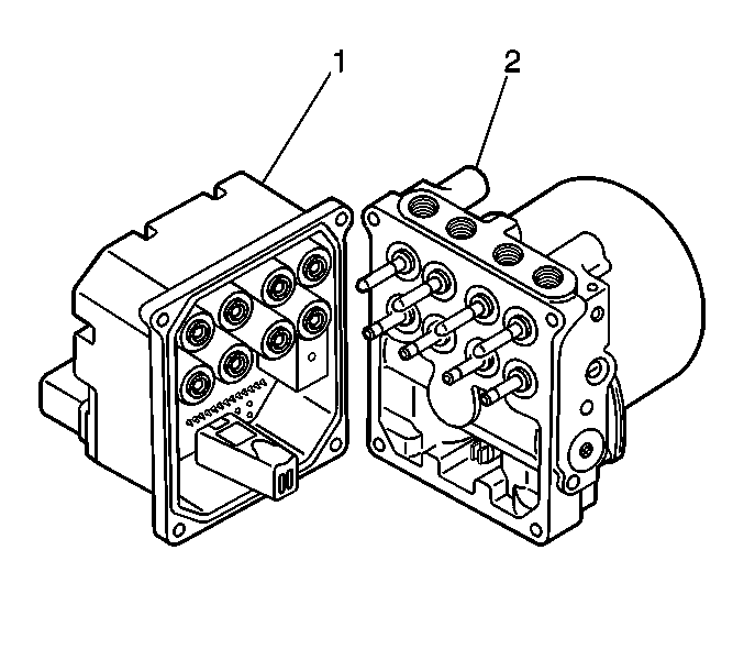
- Separate the EBCM (1) from the BPMV (2) by carefully pulling apart.


Important: Prior to disconnecting the brake pipes from the ABS modulator assembly, note the locations of the brake pipes to the valve assembly, to aid during installation.


Important:
• Do not pry apart the EBCM (1) from the BPMV (2) using a
tool. Be careful not to damage seal on the EBCM or the mating surface of the BPMV. • Care must be taken not to damage the solenoids when the EBCM is removed
from the BPMV.
Installation Procedure
Important: When installing a new brake modulator assembly, do NOT remove the shipping plugs from the pipe ports until after installation into the vehicle.
- Clean the seal and sealing surface of the EBCM, with denatured alcohol and a clean shop cloth.
- If the BPMV that was removed is being reinstalled, clean the sealing surface of the BPMV, with denatured alcohol and a clean shop cloth.
- Install the EBCM (1) to the BPMV (2). Use care when aligning the EBCM to the BPMV electrical terminals.
- Install the 4 EBCM-to-BPMV retaining bolts. Tighten the bolts in a criss-cross pattern.
- Install the EBCM/BPMV assembly to the mounting bracket.
- Install the EBCM/BPMV assembly to mounting bracket bolt.
- Remove the caps from the master cylinder brake pipe ends.
- Remove the plugs from the master cylinder ports on the BPMV.
- Connect the master cylinder brake pipes (1) to the BPMV, in the same location as removed. Refer to Hydraulic Brake Pipe Routing - Master Cylinder to ABS in Hydraulic Brakes.
- Tighten the brake pipe fittings at the BPMV.
- Remove the caps from the caliper and wheel cylinder brake pipe ends.
- Remove the plugs from the caliper and wheel cylinder ports on the BPMV.
- Connect the caliper and wheel cylinder brake pipes (2) to the BPMV, in the same location as removed. Refer to Hydraulic Brake Pipe Routing - Master Cylinder to ABS in Hydraulic Brakes.
- Tighten the brake pipe fittings at the BPMV.
- Connect the electrical harness connector (4) to the EBCM (3).
- Depress the cover lock tab, then move the sliding connector cover (2) to the home position to lock.
- Engage the electrical connector CPA locking tab (1) to the connector sliding cover lock tab.
- Perform the Antilock Brake System Automated Bleed Procedure .
- Perform the ABS Diagnostic System Check. Refer to Diagnostic System Check - ABS .

Notice: Refer to Fastener Notice in the Preface section.
Tighten
Tighten the bolts to 5 N·m (44 lb in).

Tighten
Tighten the bolt to 10 N·m (89 lb in).

Tighten
Tighten the fittings to 24 N·m (18 lb ft).
Tighten
Tighten the fittings to 24 N·m (18 lb ft).


Important: Do NOT start the engine, but only turn the ignition switch to the ON position.
