SERVICE MANUAL UPDATE-SEC. 1B A/C EVAPORATOR (FRONT)

Subject: SERVICE MANUAL UPDATE, SECTION 1B, A/C EVAPORATOR (FRONT)
Models Affected: 1990-93 TRANS SPORT MODELS
This bulletin serves to cancel and supersede the A/C front evaporator procedures found in Section 1B of the 1990-93 Pontiac Trans Sport Service Manual. Use this procedure whenever service of the A/C evaporator (front) is necessary.
A/C Evaporator (Front) ---------------------- REMOVE or DISCONNECT -------------------- o Recover refrigerant. Refer to SECTION 1B.
o Drain engine coolant. Refer to SECTION 6B.
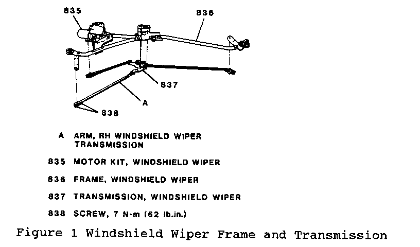
1. Two screws (838) attaching RH windshield wiper transmission (837) arm to windshield wiper frame (836) (Figure 1).
o Move RH windshield wiper transmission arm aside to gain access to heater hoses.
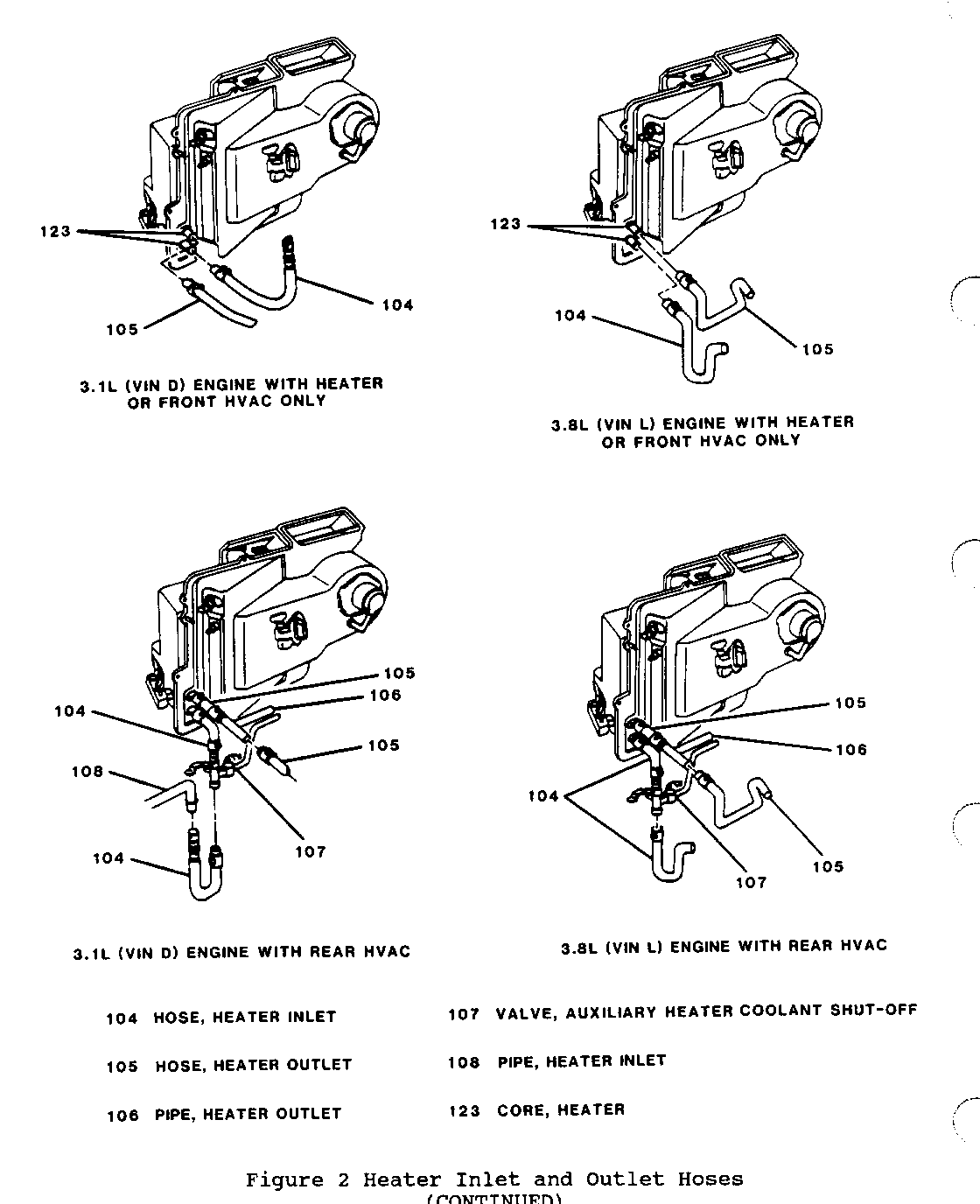
2. Clamp and heater outlet hose (105) from heater core (123) (Figure 2).
3. Clamp and heater inlet hose (104) from heater core (123) (Figure 2).
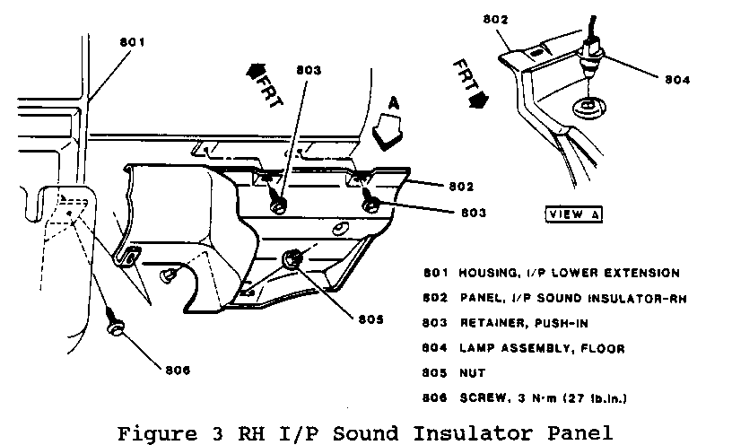
4. RH I/P sound insulator panel push-in retainers (803), screw (806) and nut (805) from stud (Figure 3).
o Carefully pull RH I/P sound insulator panel (802) away from I/P (Figure 3).
5. Floor (courtesy) lamp (804) from RH I/P sound insulator panel (802) (Figure 3).
6. RH I/P sound insulator panel (802) from vehicle (Figure 3).
o Open I/P compartment door.
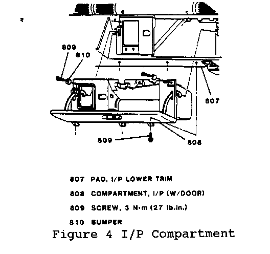
7. Three screws (809) from bottom of I/P compartment insert (808) (Figure 4).
8. Three upper I/P compartment screws (809) with two bumpers (810) (Figure 4).
9. Electrical connector from I/P compartment lamp and switch assembly.
10. I/P compartment (with door) (808) from I/P (Figure 4).
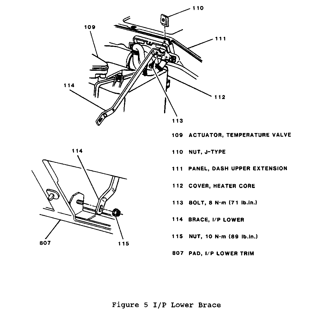
11. Bolt (113) and nut (115) from I/P lower brace (114) (early model vehicles) (Figure 5).
12. I/P lower brace (114) from I/P (early model vehicles) (Figure 5).
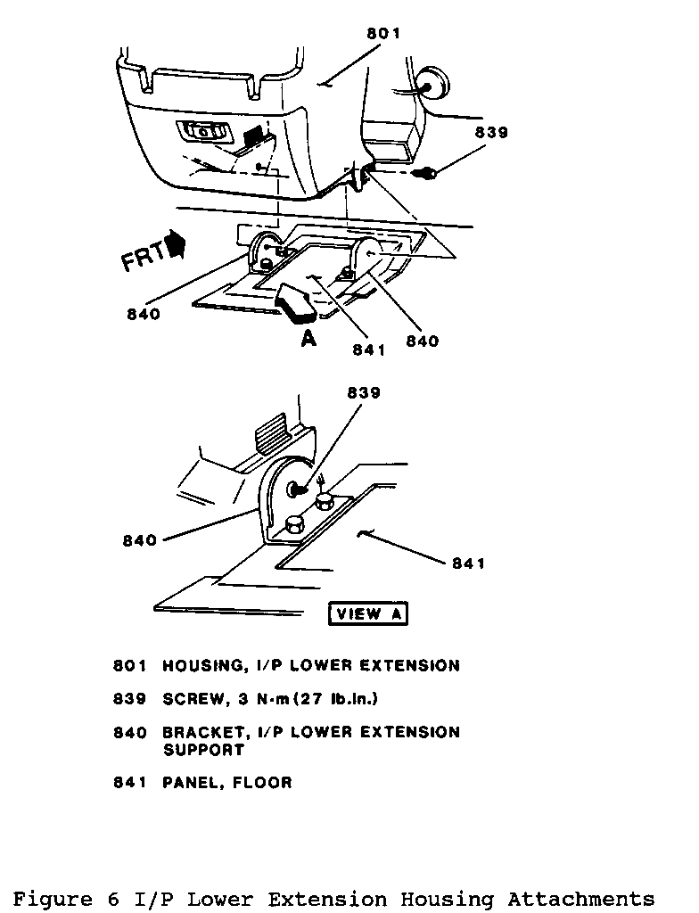
13. Two screws (839) retaining I/P lower extension housing (801) to I/P lower extension support brackets (840) (1993 vehicles only) (Figure 6).
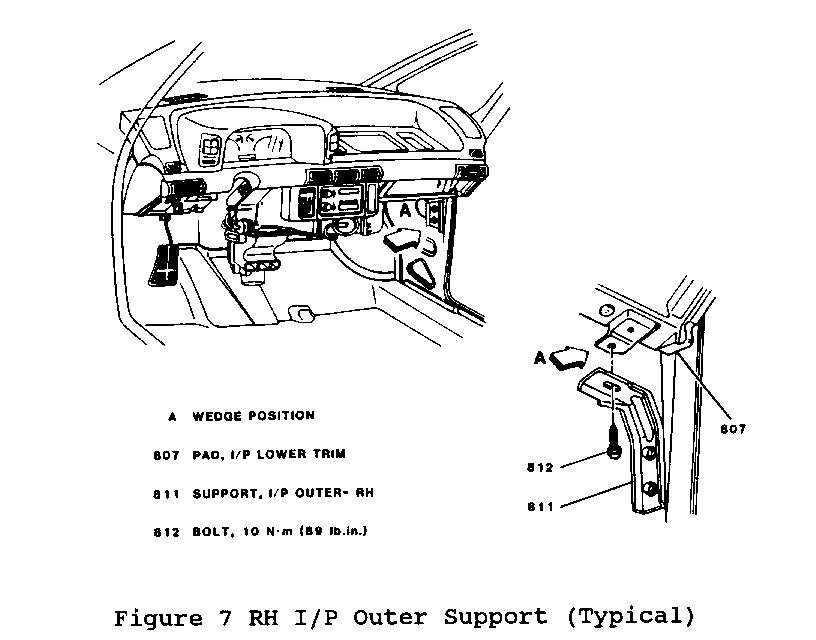
14. RH I/P outer support-to-I/P lower trim pad attaching bolt (812) (Figure 7).
o Position wedge between RH I/P outer support (811) and I/P lower trim pad (807) (Figure 7). Wedge will provide sufficient clearance for removal and installation of heater core.
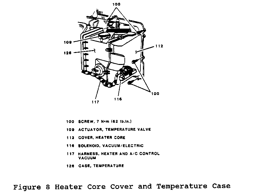
15. Heater and A/C control vacuum harness (117) from vacuum/electric solenoid (116) (Figure 8).
16. Two screws retaining vacuum/electric solenoid (116) (Figure 8).
17. Vacuum/electric solenoid (116) from heater core cover (112) (Figure 8).
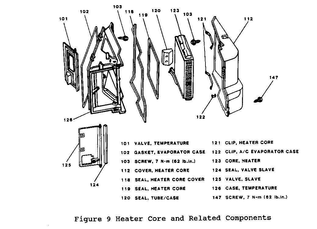
18. Six screws (147) and two clips (122) from heater core cover (112) (Figure 9).
19. Heater core cover (112) and seal (118) from temperature case (126) (Figure 9).
20. Heater core lower bracket retaining screw (late model vehicles).
21. Heater core lower bracket (late model vehicles).
22. LH retaining screw from heater core upper bracket (late model vehicles).
o Loosen RH retaining screw from heater core upper bracket (late model vehicles).
o Adjust heater core upper bracket to allow heater core removal (late model vehicles).
23. Heater core inlet/outlet tubes from tube/case seal (120) (Figure 9).
24. Heater core (123) and seal (119) from temperature case (126) (Figure 9).
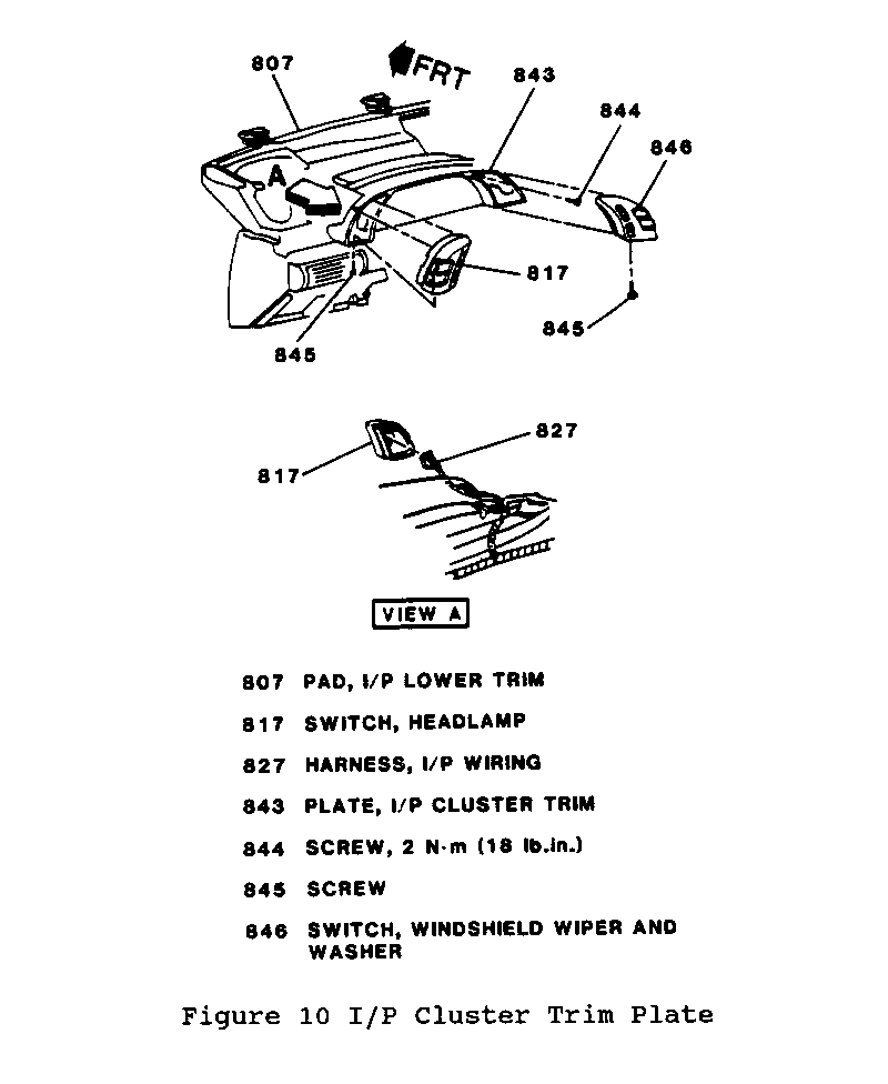
25. Windshield wiper and washer switch retaining screw (845) (Figure 10).
26. Windshield wiper and washer switch (846) from I/P cluster trim plate (843) (Figure 10). Disconnect electrical connector from switch.
27. Headlamp switch retaining screw (845) (Figure 10).
28. Headlamp switch (817) from I/P cluster trim plate (843) (Figure 10). Disconnect electrical connector from switch.
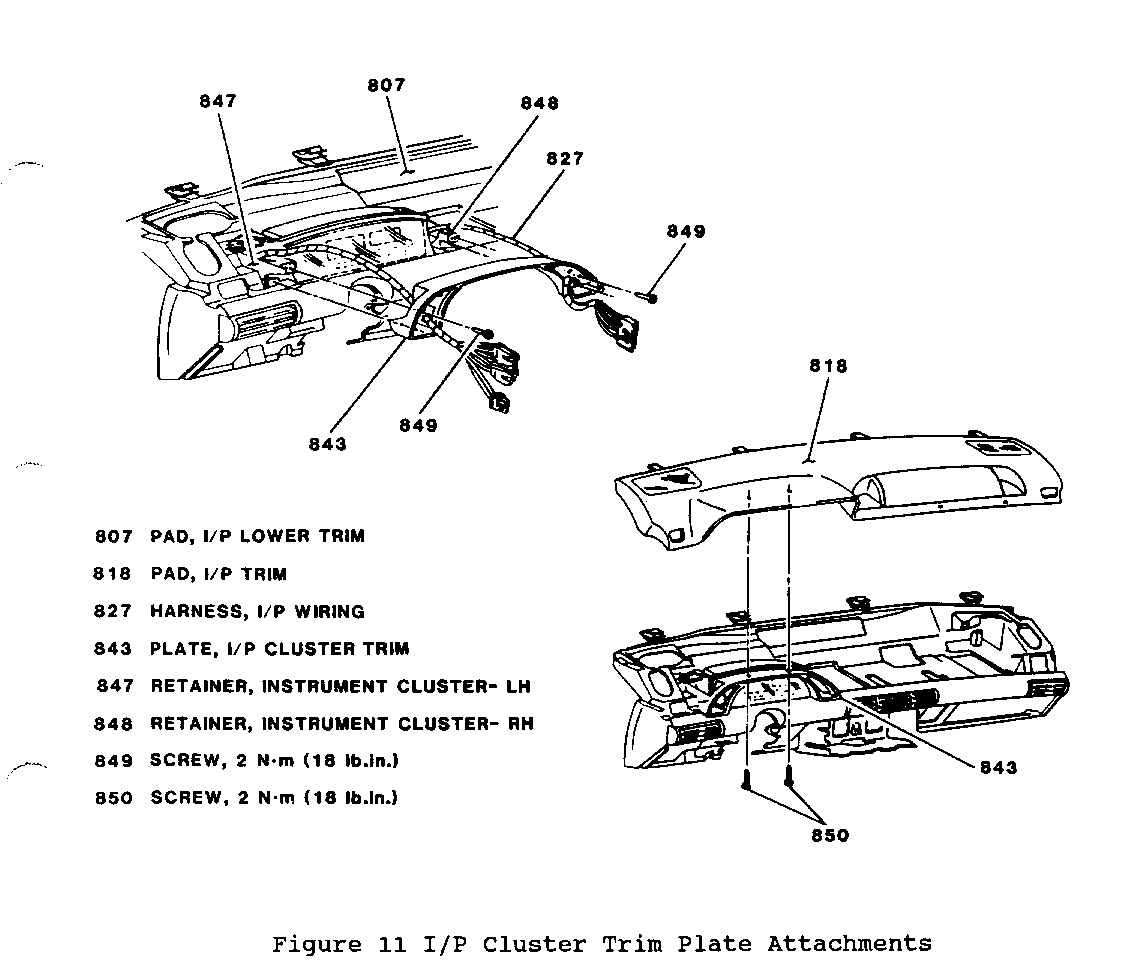
29. Two screws (849) attaching I/P cluster trim plate (843) to LH and RH instrument cluster retainers (847 and 848) (Figure 11).
30. Two screws (850) attaching I/P cluster trim plate (843) to I/P trim pad (818) (Figure 11).
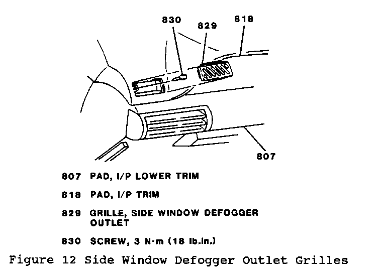
31. LH and RH side window defogger outlet grilles (829) from I/P trim pad (818) (Figure 12).
32. Screws (830) behind side window defogger outlet grilles (829) (one on each side of I/P trim pad) (Figure 12).
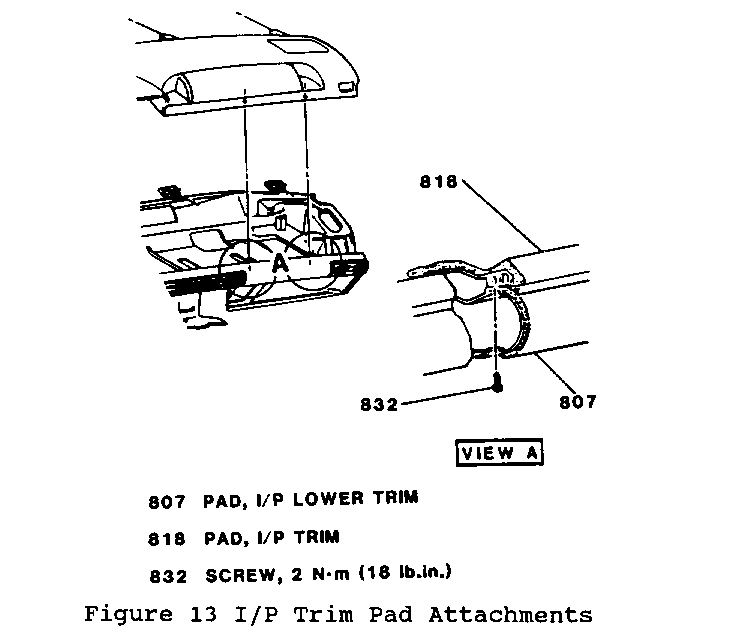
33. Two screws (832) (above I/P compartment area) retaining I/P trim pad (818) to I/P lower trim pad (807) (Figure 13).
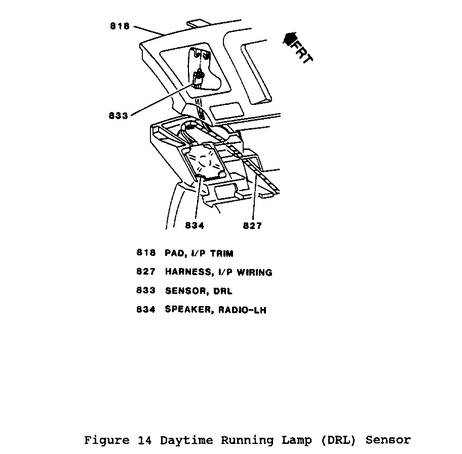
34. DRL sensor (833) from I/P trim pad (818) (if equipped) (Figure 14).
35. I/P trim pad (818) from I/P lower trim pad (807).
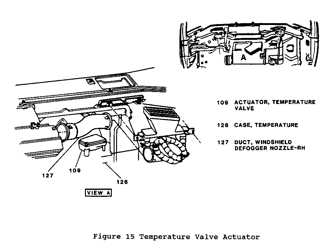
36. Electrical connector and harness from temperature valve actuator (109) (Figure 15).
37. Two screws from temperature valve actuator (109) and actuator from temperature case (126) (Figure 15).
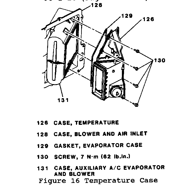
38. Two lower screws (130) from temperature case (Figure 16).
39. One upper LH screw (130), one upper RH screw (130), temperature case (126) and gasket (129) from blower and air inlet case (128) (Figure 16). Removal of upper RH temperature case screw (130) may require partial removal of adhesive insulator patch.
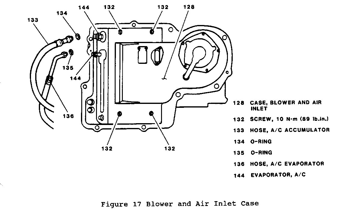
40. A/C accumulator hose (133) from A/C evaporator (144) (Figure 17).
41. A/C evaporator hose (136) from A/C evaporator (144) (Figure 17).
42. Four screws (132) retaining auxiliary A/C evaporator and blower case (131) to blower and air inlet case (128) (Figure 17).
43. Windshield defogger nozzle duct (127) (Figure 15).
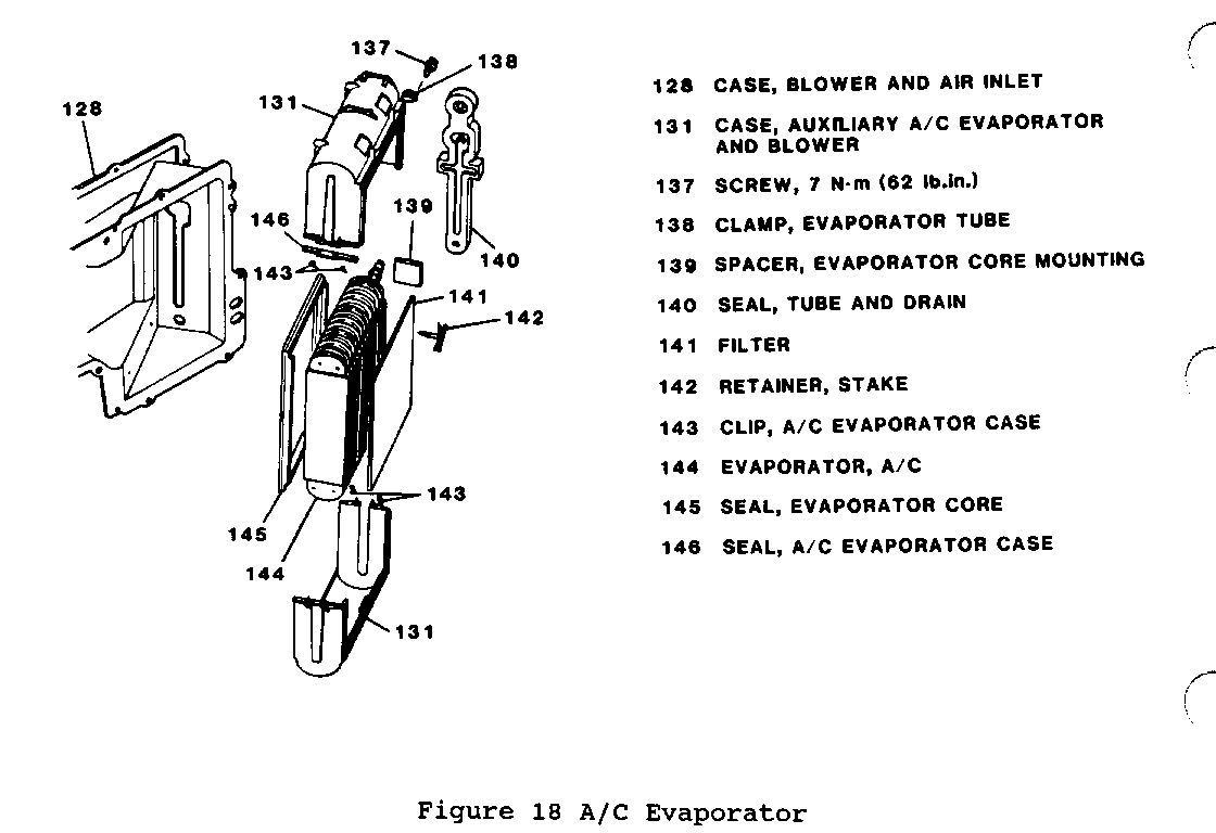
44. A/C evaporator (144) inlet/outlet tubes from drain grommet and A/C evaporator (with case) from blower and air inlet case (128) (Figure 18).
45. Tube and drain seal (140) from A/C evaporator (144) (Figure 18).
46. One screw (137) retaining evaporator tube clamp (138) (Figure 18).
47. Four A/C evaporator case clips (143) (Figure 18).
o Separate upper and lower auxiliary A/C evaporator and blower case halves (131) (Figure 18).
48. Six stake retainers (142) and filter (141) from A/C evaporator (Figure 18).
49. Evaporator core mounting spacers (139) (Figure 18).
50. Evaporator core seal (145) (Figure 18).
INSPECT
1. A/C evaporator (144) for signs of damage, leakage or internal restriction. Replace as necessary.
2. Evaporator core seal (145) for damage or deformation. Replace as necessary.
3. Tube and drain seal (140) for damage or deformation. Replace as necessary.
4. Drain grommet for damage or deformation. Replace as necessary.
INSTALL or CONNECT
1. Evaporator core seal (145) (Figure 18).
2. New evaporator core mounting spacers (139) (Figure 18).
3. New filter (141) to A/C evaporator (144) with six stake retainers (142) (Figure 18).
4. A/C evaporator (144) into upper and lower auxiliary A/C evaporator and blower case halves (131) (Figure 18).
5. Upper and lower auxiliary A/C evaporator and blower case halves (131) with four A/C evaporator case clips (143) (Figure 18).
6. Evaporator tube clamp (138) with screw (137) (Figure 18).
Tighten
o Evaporator tube clamp screw (137) to 7 N.m (62 lb.in.).
7. Tube and drain seal (140) to A/C evaporator (144) (Figure 18).
8. A/C evaporator inlet/outlet tubes to drain grommet and A/C evaporator (with case) (144/131) into blower and air inlet case (128) (Figure 16).
9. Windshield defogger nozzle duct (127) (Figure 15).
10. Four screws (132) retaining auxiliary A/C evaporator and blower case (131) to blower and air inlet case (128) (Figure 17).
Tighten
o Auxiliary A/C evaporator and blower case screws (132) to 10 N.m (89 lb.in.).
IMPORTANT
o Lubricate new 0-ring seals prior to installation with 525 viscosity mineral refrigerant oil only. Do not use PAG oil to lubricate 0-ring seals.
11. A/C evaporator hose (136) to A/C evaporator (144) with new 0-ring seal (135) (Figure 17).
12. A/C accumulator hose (133) to A/C evaporator (144) with new 0-ring seal (134) (Figure 17).
13. Temperature case (126) and gasket (129) to blower and air inlet case with two upper screws (130) (Figure 16).
Tighten
o Upper temperature case-to-blower and air inlet case screws (130) to 7 N.m (62 lb.in.).
14. Two lower screws (130) to temperature case (Figure 16).
Tighten
o Lower temperature case-to-blower and air inlet case screws (130) to 7 N.m (62 lb.in.).
15. Temperature valve actuator (109) to temperature case (126) with two screws (Figure 15).
Tighten
o Temperature valve actuator screws to 8 N.m (71 lb.in.).
16. Electrical connector and harness to temperature valve actuator (109) (Figure 15).
17. DRL sensor (833) to I/P trim pad (818) (if equipped) (Figure 14).
o Position I/P trim pad (818) onto I/P lower trim pad (807).
18. Two screws (832) (above I/P compartment area) attaching I/P trim pad (818) to I/P lower trim pad (807) (Figure 13).
Tighten
o I/P trim pad-to-I/P lower trim pad attaching screws (832) to 2 N.m (18 lb.in.).
19. Screws (830) behind side window defogger outlet grilles (829) (one on each side of I/P trim pad) (Figure 12).
Tighten
o I/P trim pad-to-I/P lower trim pad attaching screws (830) to 3 N.m (27 lb.in.).
20. LH and RH side window defogger outlet grilles (829) to I/P trim pad (818) (Figure 12).
21. Two screws (849) retaining I/P cluster trim plate (843) to LH and RH instrument cluster retainers (847 and 848) (Figure 11).
22. Two screws (850) retaining I/P cluster trim plate (843) to I/P trim pad (818) (Figure 11).
Tighten
o I/P cluster trim plate retaining screws to 2 N.m (18 lb.in.).
23. Electrical connector to headlamp switch (817).
24. Headlamp switch (817) to I/P cluster trim plate (843) and secure with retaining screw (845) (Figure 10).
25. Electrical connector to windshield wiper and washer switch (846).
26. Windshield wiper and washer switch (846) to I/P cluster trim plate (843) and secure with retaining screw (845) (Figure 10).
27. Heater core inlet/outlet tubes into tube/case seal (120) and heater core (123) and seal (119) into temperature case (126) (adjusting heater core upper bracket if equipped) (Figure 9).
28. LH retaining screw to heater core upper bracket - do not fully tighten (late model vehicles).
29. Heater core lower bracket with retaining screw (late model vehicles).
o Adjust positioning of heater core in temperature case to prevent any movement.
Tighten
o Heater core bracket retaining screws to 3 N.m (27 lb. in.).
30. Heater core cover (112) and seal (118) to temperature case (126) with six screws (147) and two clips (122) (Figure 9).
Tighten
o Heater core cover screws (147) to 7 N.m (62 lb.in.).
31. Vacuum/electric solenoid (116) to heater core cover (112) with two screws (Figure 8).
Tighten
o Vacuum/electric solenoid screws to 7 N.m (62 lb.in.).
32. Heater and A/C control vacuum harness (117) to vacuum/electric solenoid (116) (Figure 8).
o Remove wedge from between RH I/P outer support (811) and I/P lower trim pad (807) (Figure 7).
33. RH I/P outer support-to-I/P lower trim pad attaching bolt (812) (Figure 7).
Tighten
o RH I/P outer support-to-I/P lower trim pad attaching bolt (812) to 10 N.m (89 lb.in.).
34. Two screws (839) retaining I/P lower extension housing (801) to I/P lower extension support brackets (840) (Figure 6).
Tighten
o I/P lower extension housing-to-I/P lower extension support bracket screws to 3 N.m (27 lb.in.).
35. I/P lower brace (114) with nut (115) and bolt (113) (early model vehicles) (Figure 5).
Tighten
o I/P lower brace nut (115) to 10 N.m (89 lb.in.).
o I/P lower brace bolt (113) to 8 N.m (71 lb.in.).
36. Electrical connector to I/P compartment lamp and switch assembly while positioning I/P compartment into I/P (with door open).
37. Three upper I/P compartment screws (809) with two bumpers (810) (Figure 4).
38. Three lower I/P compartment screws (809) (Figure 4).
Tighten
o I/P compartment screws (809) to 3 N.m (27 lb.in.).
o Close I/P compartment door.
39. Floor (courtesy) lamp (804) to RH I/P sound insulator panel (802) while positioning panel into I/P (Figure 3).
40. RH I/P sound insulator panel screw (806), nut (805) and push-in retainers (803) (Figure 3).
Tighten
o RH I/P sound insulator panel attaching screw (806) to 3 N.m (27 lb.in.)
41. Heater inlet hose (104) to heater core (123) and secure with clamp (Figure 2).
42. Heater outlet hose (105) to heater core (123) and secure with clamp (Figure 2).
43. Two screws (838) attaching RH windshield wiper transmission (837) arm to windshield wiper frame (836) (Figure 1).
Tighten
o RH windshield wiper transmission arm-to-windshield wiper frame screws (838) to 7 N.m (62 lb.in.).
o Refill engine coolant. Refer to SECTION 6B.
o Recharge refrigerant. Refer to SECTION 1B.
WARRANTY INFORMATION:
Labor Operation: D3320
New Labor Time: 2.7 Hrs.
General Motors bulletins are intended for use by professional technicians, not a "do-it-yourselfer". They are written to inform those technicians of conditions that may occur on some vehicles, or to provide information that could assist in the proper service of a vehicle. Properly trained technicians have the equipment, tools, safety instructions and know-how to do a job properly and safely. If a condition is described, do not assume that the bulletin applies to your vehicle, or that your vehicle will have that condition. See a General Motors dealer servicing your brand of General Motors vehicle for information on whether your vehicle may benefit from the information.
