SLIDING SIDE DOOR HARD TO OPEN AND CLOSE, NEW PARTS RELEASED

SUBJECT: SLIDING SIDE DOOR, HARD TO OPEN/CLOSE (DIAGNOSIS, NEW PARTS, PROCEDURES)
VEHICLES AFFECTED: 1990-91 U-VANS
THIS BULLETIN CANCELS PRODUCT SERVICE BULLETIN NUMBER 90-2-214.
APPLICATION: 1990 and 1991 U-Vans prior to 1991 VIN Breakpoints
Chevrolet - MT119199 Oldsmobile - MT304917 Pontiac - MT210092 Cargo - MT119205
Conditions: Some customers may comment about sliding side doors that are hard to open or close when operating;
1. from the outside of the vehicle. 2. from the inside of the vehicle.
Causes: 1. Hard opening/closing efforts from the outside may be due to:
a. binding conditions of a misaligned/misadjusted door.
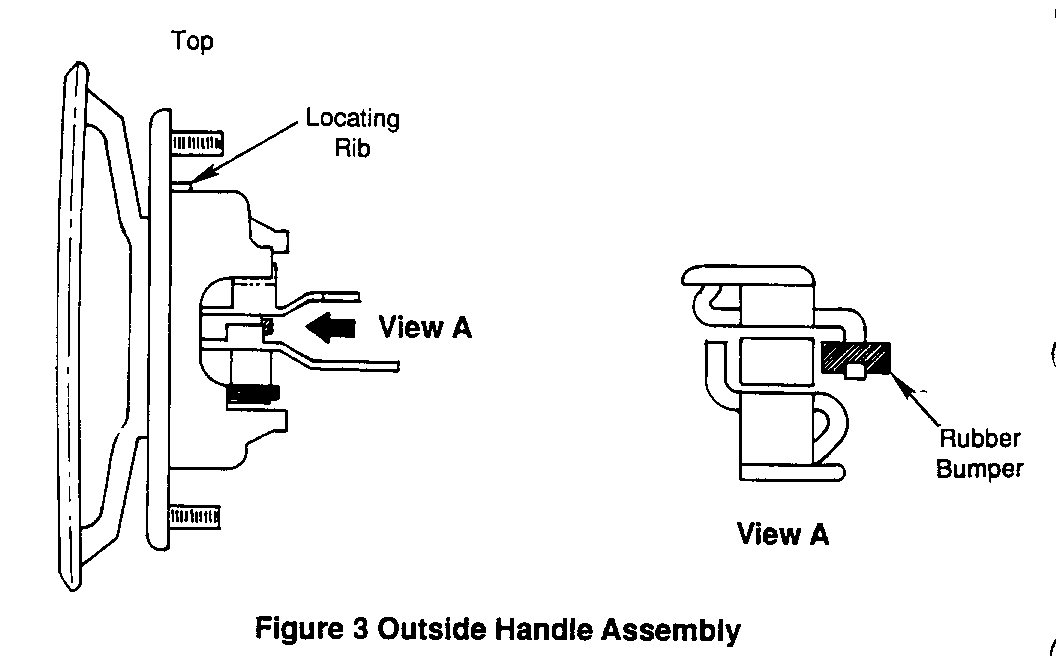
b. rubber bumper missing from levers on the outside handle, (related to closing efforts, hard to unlatch from open position).
c. binding at lower latch when closing.
d. sticking of the weatherstrip to the painted surfaces of the door opening.
2. Hard opening efforts from the inside may be due to:
a. binding conditions of a misaligned/misadjusted door.
b. broken or cracked inside handle casting limiting rod travel.
c. binding at the lower latch when closing.
d. sticking of the weatherstrip to the painted surfaces of the door opening.
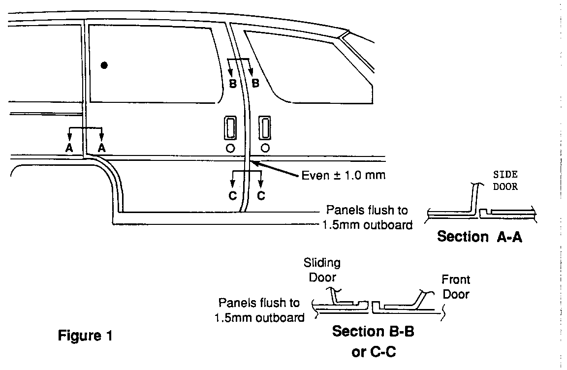
Diagnosis: 1. When properly aligned, the sliding side door should present a uniform even appearance regarding GAP in side view, refer to figure 1. The section views in Figure 1 will provide the dimensions and tolerance ranges for flushness checks. If alignment of the door is suspect, refer to Correction # 1, install new rear centre roller bracket and apply a coating of silicone to the weatherstrip.
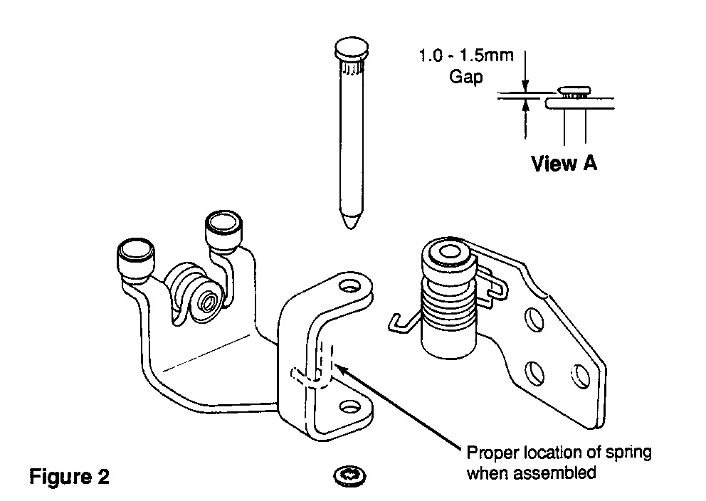
NOTE: New Rear Centre Roller Bracket Assembly consists of the following: Refer to figure 2
1 -10196002 - Bracket, Rear Centre Side door roller 1 -10196003 - Bracket, Rear Centre Side door (door side) 1 -10196004 - Pin, Rear Centre Side door bracket 1 -10186320 - Retainer, Rear Centre Roller Bracket pin
2. Outside handles suspected of missing a rubber bumper may be checked by lightly moving the handle fore/aft and noting free play present. If handle has more than slight free play (1.0 to 2.0 mm), OR if the handle does not return to a "centered" position when released, rubber bumper is probably missing, refer to Correction # 2, (refer to figure 3).
3. Broken/cracked inside handles may be identified by close visual inspection of the pivot area on the handle, OR if the handle does not return to a "centered" position when released, refer to Correction # 3.
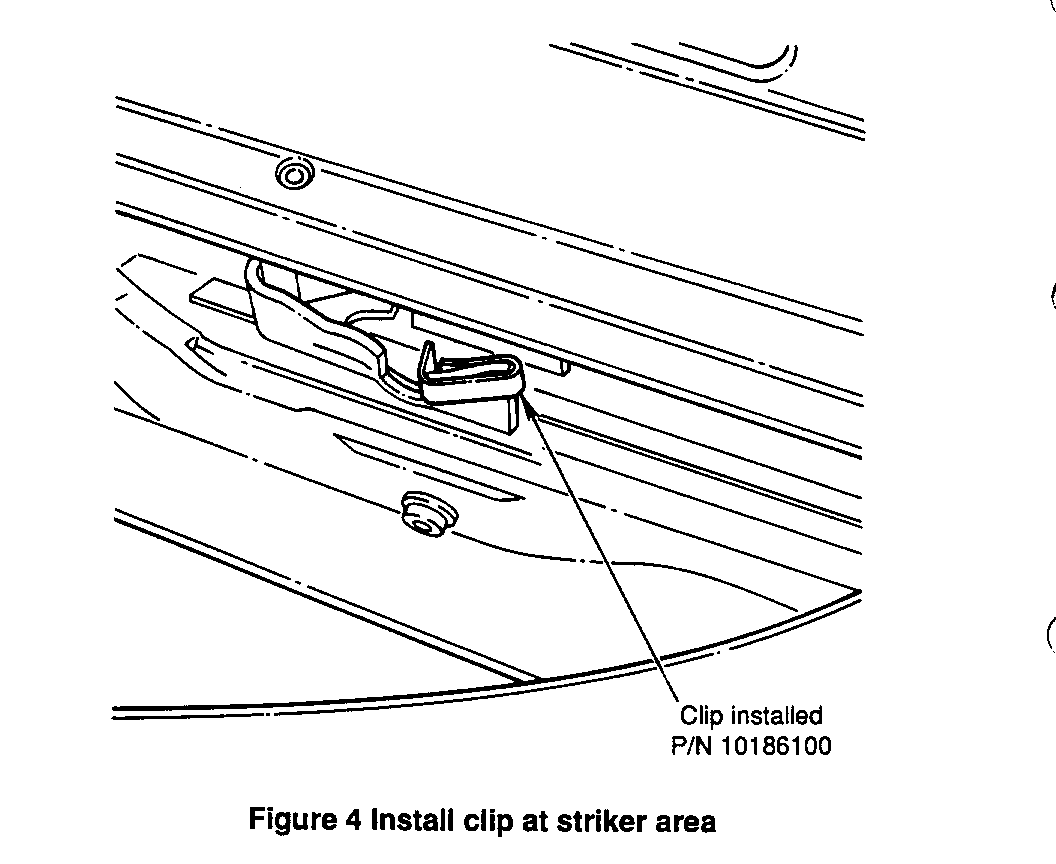
4. Binding when closing may occur at the lower bracket latch and striker area. Ensure that new clip P/N 10186100 is installed when doing Corrections # 2 OR # 3, refer to figure 4.
Correction #1 CHECK DOOR ALIGNMENT, REFER TO FIGURE 1 REPLACE REAR CENTRE ROLLER BRACKET, REFER TO FIGURE 2, AND APPLY SILICONE TO WEATHERSTRIPS.
1. Obtain new rear centre roller bracket parts.
Important: Prepaint the centre roller and bracket parts body colour.
2. Prior to assembly, lube the bushings and pin with 30 wt. motor oil or light grease. Preassemble the roller bracket and place a socket under the hinge for support and pin clearance. Use a small ball peen hammer to tap the pin into position, leaving the head of the hinge pin between 1.0 to 1.5 mm from fully seated (see Figure 2 view A) and install the retainer. 3. Open the sliding side door and mark the location of the bracket on the door side surface. 4. Use a floor jack to support the door. Pad the lower edge to protect the finish. 5. Remove the rear centre roller bracket to door attaching bolts. 6. Carefully swing the rear edge of the door outward to provide clearance and slide the roller bracket forward to the end of the track.
Important: Prior to roller removal, it may be necessary to bend the front 76mm (3") of the centre track upper flange SLIGHTLY OUTWARD for ease of roller removal and installation.
7. Rotate the bracket upward and remove the assembly from the track. 8. Install the new roller bracket in the track and slide rearward to the end of the track. 9. Position the bracket within the previously marked area on the door, install and tighten the bolts. 10. Remove the floor jack and CAREFULLY CLOSE DOOR TO INSPECT FOR PROPER ALIGNMENT. 11. After ensuring proper alignment, apply a light coating of silicone to the weatherstrip surfaces to reduce sticking.
ADJUSTMENT PROVISIONS:
UP/DOWN ADJUSTMENTS ARE MADE AT: --------------------------------- 1. Lower front bracket which has slots for adjustment (REQUIRES TRIM PANEL REMOVAL). 2. Rear centre roller bracket which has oversize holes for adjustment.
IN / OUT ADJUSTMENTS ARE MADE AT: ---------------------------------- 1. Upper front bracket which has slots for adjustment at door side. 2. Lower front bracket which has shims to add or remove (REQUIRES TRIM PANEL REMOVAL). Shim P/N 10122453. 3. Rear centre roller bracket which has oversize holes for adjustment.
FORE / AFT ADJUSTMENTS ARE MADE AT: ------------------------------------ 1. Rear centre roller bracket which has shims to add or remove. Shim P/N 10173144.
Correction # 2 OUTSIDE HANDLE, INSTALL RUBBER BUMPER OR REPLACE HANDLE (REFER TO FIGURE 3)
INSPECT FOR AND INSTALL CLIP AT LOWER LATCH STRIKER (REFER TO FIGURE 4)
1. Remove the outside handle as described in Section 10-5 of the Service Manual. 2. Install new bumper P/N 10201662 on the handle lever, refer to figure 3. 3. Reinstall the handle as described in Section 10-5 of the Service Manual. 4. If lower latch striker does not have clip, install clip P/N 10186100, refer to figure 4.
IMPORTANT: In some cases, it may be necessary to adjust the hold open cable attachment for proper operation. This may be accomplished by loosening the screw on top of the lower roller bracket and rotating the cable attachment to remove excess slack in the cable.
Correction # 3: REPLACE INSIDE HANDLE ASSEMBLY. INSPECT FOR AND INSTALL CLIP AT LOWER LATCH STRIKER REFER TO FIGURE 4
1. Replace the inside handle assembly as described in Section 10-5 of the Service Manual. 2. If lower latch striker does not have clip, install clip P/N 10186100, refer to figure 4.
IMPORTANT: In some cases, it may be necessary to adjust the hold open cable attachment for proper operation. This may be accomplished by loosening the screw on top of the lower roller bracket and rotating the cable attachment to remove excess slack in the cable.
Use the most applicable Labour Operation and Time from the Canadian Labour Time Guide.


General Motors bulletins are intended for use by professional technicians, not a "do-it-yourselfer". They are written to inform those technicians of conditions that may occur on some vehicles, or to provide information that could assist in the proper service of a vehicle. Properly trained technicians have the equipment, tools, safety instructions and know-how to do a job properly and safely. If a condition is described, do not assume that the bulletin applies to your vehicle, or that your vehicle will have that condition. See a General Motors dealer servicing your brand of General Motors vehicle for information on whether your vehicle may benefit from the information.
