Removal Procedure
-
Important: Relief the fuel pressure. Refer to Fuel Pressure in Engine Fuel.
- Remove the upper intake manifold. Refer to Upper Intake Manifold Replacement .
- Remove the fuel lines. Refer to Fuel Lines in Engine Fuel.
- Remove the fuel rail. Refer to Fuel Rail in Engine Fuel.
- Disconnect the wiring harness connectors.
- Remove the coolant hose. Refer to Coolant Hose in Cooling and Radiator.
- Remove the drive belt.
- Remove the generator bracket and braces. Refer to Generator in Charging System.
- Remove the power steering pump. Refer to Power Steering Gear and Pump On-Vehicle Service.
- Remove the upper radiator hose. Refer to Power Steering Gear and Pump On-Vehicle Service.
- Disconnect the heater inlet pipe from the manifold.
- Remove the ignition coil bracket.
- Remove the engine mount strut. Refer to Engine Mount Strut Replacement Engine Mount Strut Replacement.
- Remove the valve rocker arm cover. Refer to Valve Rocker Arm Cover Replacement and Valve Rocker Arm Cover Replacement .
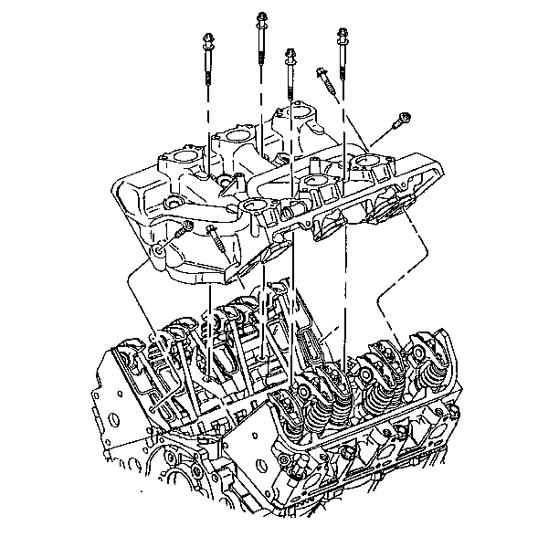
- Remove the lower intake bolts.
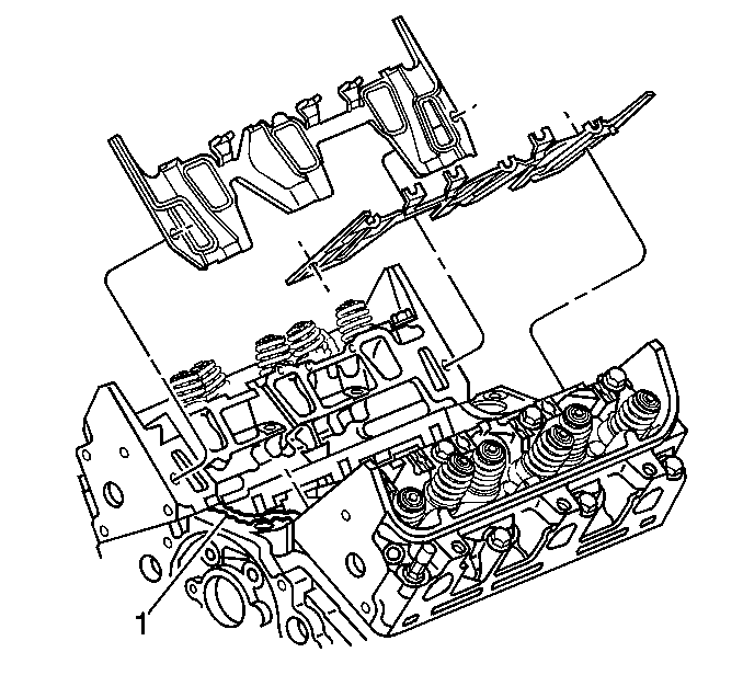
- Remove the lower intake manifold.


Installation Procedure
- Place 8-12 mm (0.08-0.11 inch) bead of RTV Sealer, GM P/N 12345739 or equivalent, on each ridge where front and rear of the manifold contact the engine block.
- Install the lower intake manifold gaskets.
- Install the lower intake manifold.
- Apply sealant, GM P/N 12345382 to the threads of the bolts.
- Hand tighten the vertical bolts.
- Hand tighten the diagonal bolts.
- Tighten the vertical bolts to 13 N·m (115 lb in).
- Tighten the diagonal bolts to 13 N·m (115 lb in).
- Install the valve rocker arm cover. Refer to Valve Rocker Arm Cover Replacement and Valve Rocker Arm Cover Replacement .
- Install the engine mount strut. Refer to Engine Mount Strut Replacement Engine Mount Strut Replacement.
- Install the ignition coil bracket.
- Connect the heater pipe from heater core to coolant pump.
- Connect the tie straps around the heater outlet pipe and ignition wiring harness.
- Connect the upper radiator hose at the engine.
- Connect the heater inlet pipe to the manifold.
- Position the power steering pump. Refer to Power Steering Gear and Pump On-Vehicle Service.
- Install the generator bracket brace.
- Install the accessory drive belt. Refer to Drive Belt Replacement .
- Install the coolant hose. Refer to Coolant Hose in Cooling and Radiator.
- Install the wiring harness connectors.
- Install the fuel injector rail. Refer to Fuel Injector Rail in Engine Fuel.
- Connect the fuel lines. Refer to Fuel Lines in Engine Fuel.
- Install the upper intake manifold. Refer to Upper Intake Manifold Replacement .

Notice: An oil leak may result if the vertical bolts are not tightened before the diagonal bolts.
Tighten
Notice: Use the correct fastener in the correct location. Replacement fasteners must be the correct part number for that application. Fasteners requiring replacement or fasteners requiring the use of thread locking compound or sealant are identified in the service procedure. Do not use paints, lubricants, or corrosion inhibitors on fasteners or fastener joint surfaces unless specified. These coatings affect fastener torque and joint clamping force and may damage the fastener. Use the correct tightening sequence and specifications when installing fasteners in order to avoid damage to parts and systems.


