For 1990-2009 cars only
Special Tools
| • | J-8614-01 Flange and Pulley Holding Tool |
| • | J-22928-B Seal Installer |
| • | J-42176 Universal Driver Handle - Non-Threaded |
Removal Procedure
- Remove the automatic transaxle assembly. Refer to Transmission Disassemble , Transmission Replacement for the MVB 4 speed transmission or Transmission Replacement for the MVD 5 speed transmission.
- Remove the manual transaxle assembly. Refer to Transmission Replacement for the MVC 5 speed transmission or Transmission Replacement for the MVE 5 speed transmission.
- Remove the clutch cover and disc assembly (for manual transaxle).
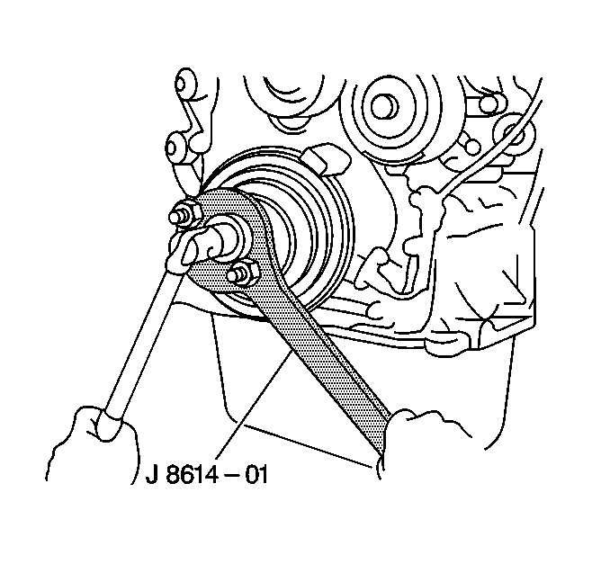
- Using J-8614-01 holding tool , hold the crankshaft.
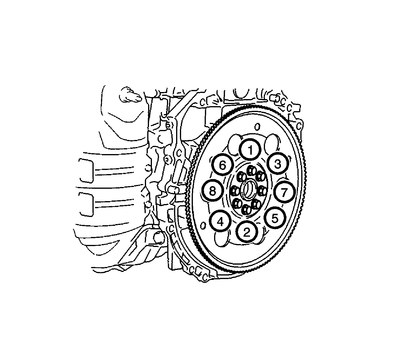
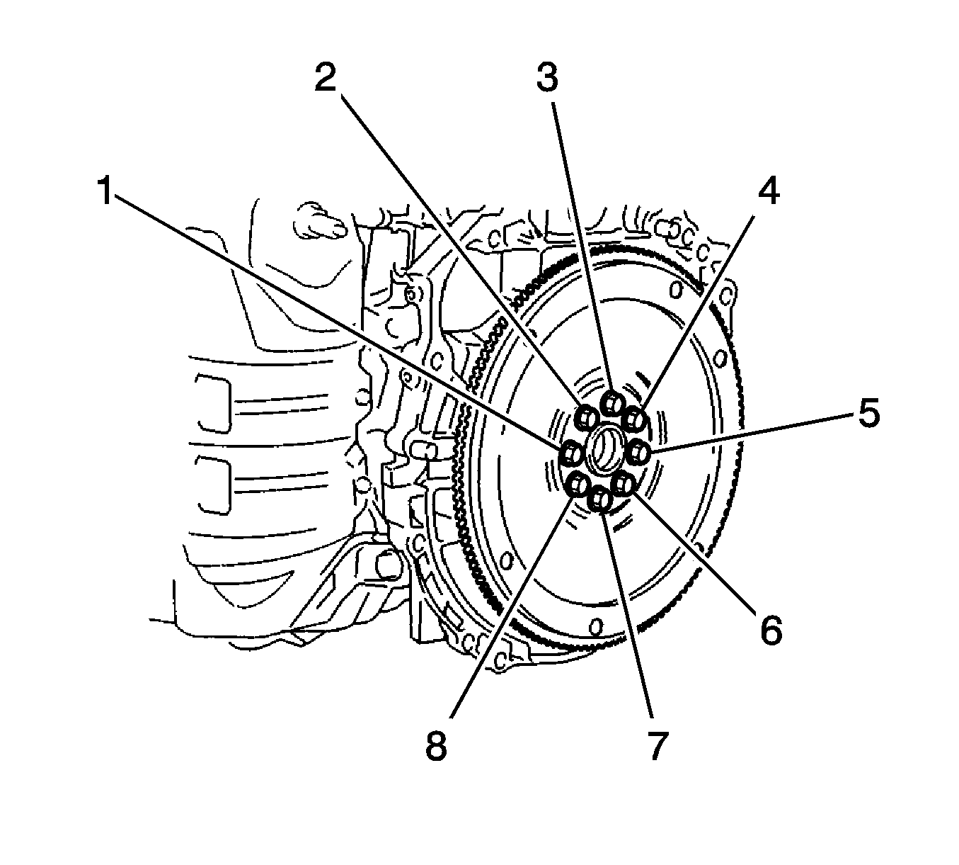
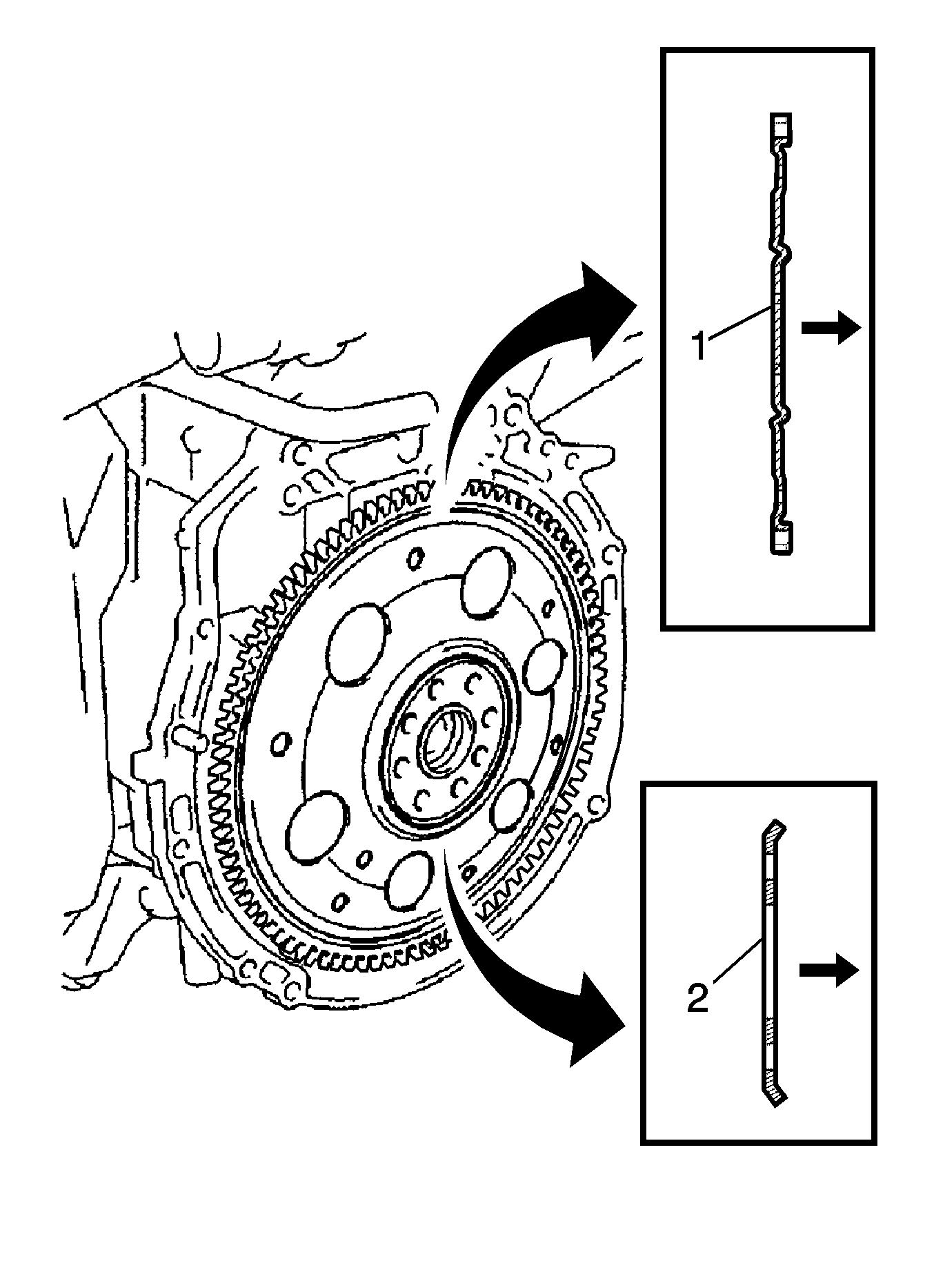
- For automatic transmissions, remove the 8 bolts (1-8), rear drive plate spacer, drive plate and front drive plate spacer.
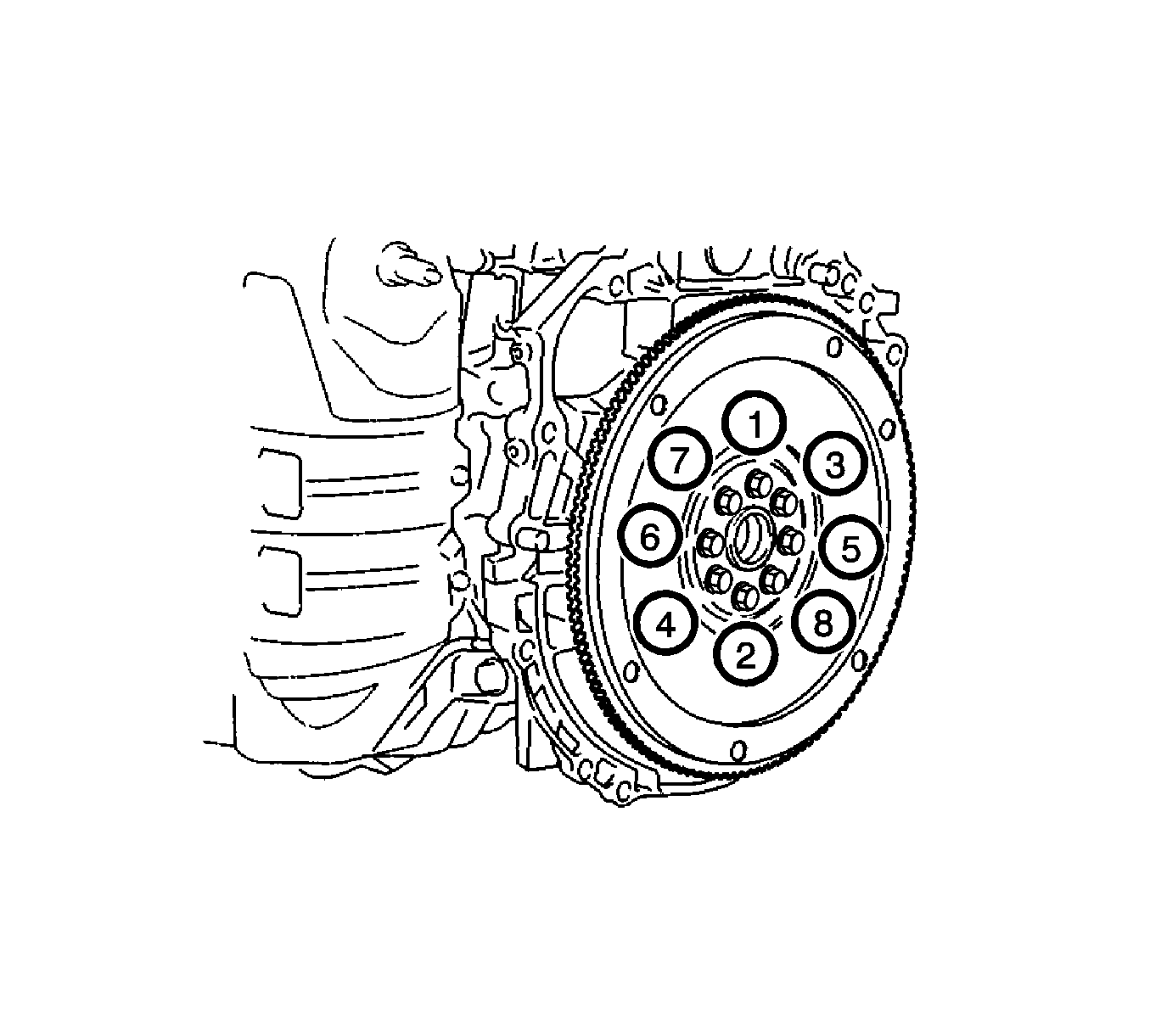
- For manual transmissions, remove the 8 bolts (1-8) and flywheel.
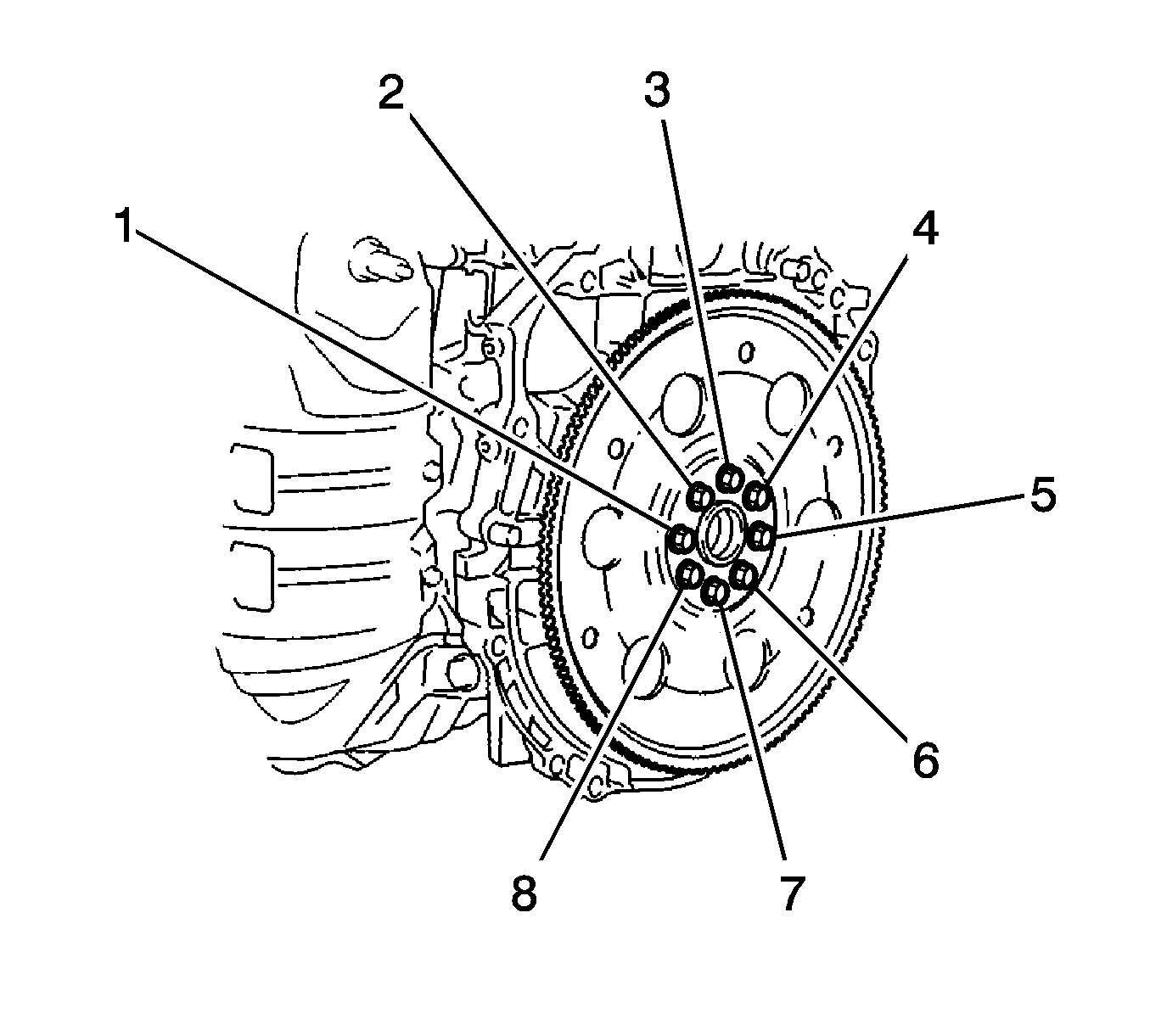
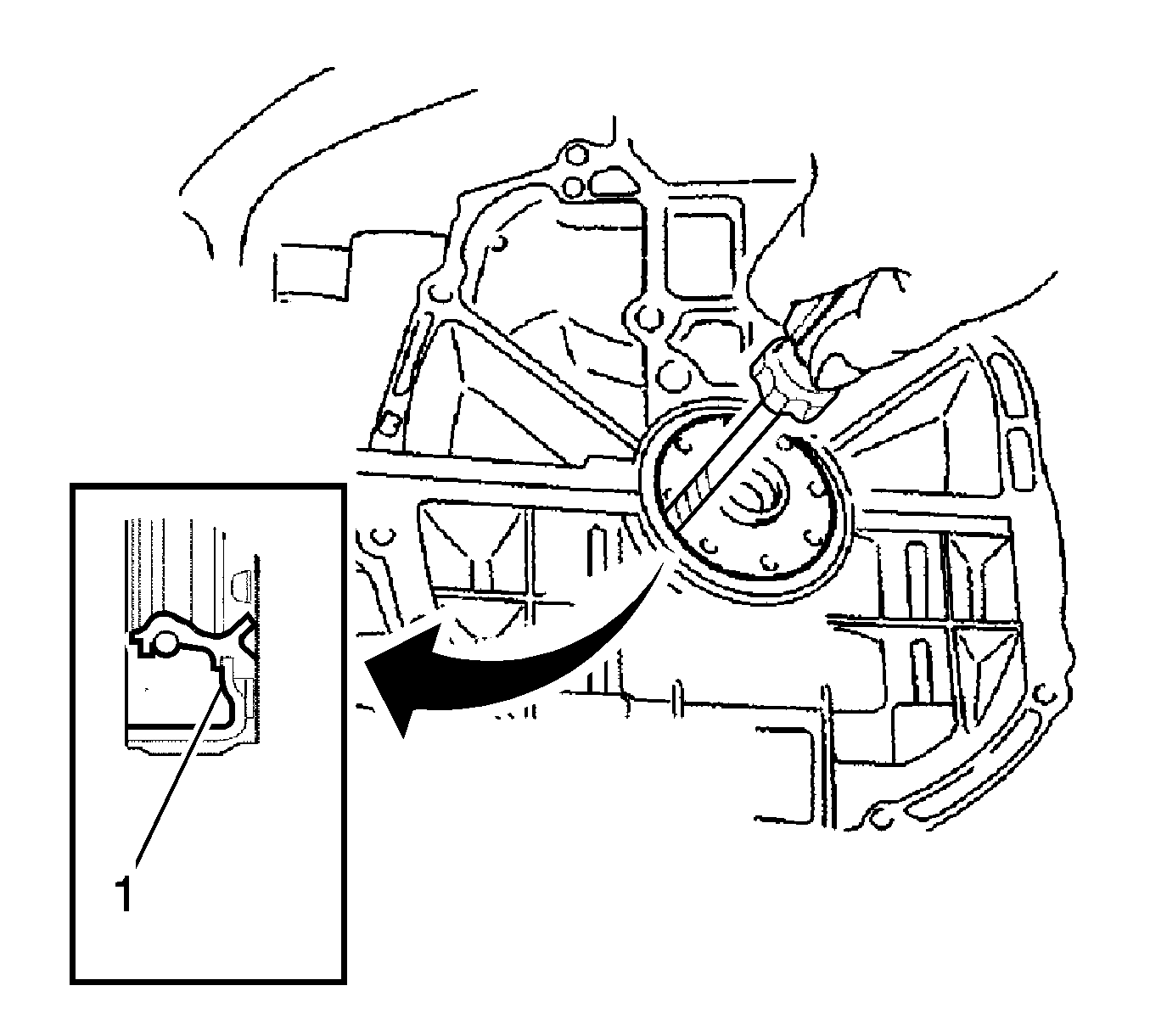
- Using a knife, cut off the lip of the oil seal (1).
- Using a screwdriver, pry out the oil seal.
Note:
• After removing, check the crankshaft for damage. If damaged, smooth the surface with 400-grit sandpaper. • Tape the screwdriver tip before use.
Installation Procedure
- Apply MP grease to the lip of a new rear crankshaft oil seal.
- Using the J-22928-B installer and a hammer (1, 2), tap in the rear crankshaft oil seal until its surface is flush with the rear oil seal retainer edge.
- For automatic transaxle, clean the 8 bolts and 8 bolt holes.
- Apply adhesive to 2 or 3 threads of the 8 bolts.
- Using the J-8614-01 holding tool , hold the crankshaft.
- Install the front drive plate spacer.
- Install the drive plate (1) and rear drive plate spacer (2) onto the crankshaft.
- In several steps, uniformly install and tighten the 8 bolts in the sequence shown in the illustration to 98 N·m (72 lb ft).
- For manual transaxle, clean the 8 bolts and 8 bolt holes.
- Apply adhesive to the end 2 or 3 threads of the 8 bolts.
- In several steps, uniformly install and tighten the 8 bolts in the sequence shown in the illustration to 130 N·m (96 lb ft).
- Install the clutch disc assembly (for manual transaxle).
- Install the clutch cover assembly (for manual transaxle).
- Install the automatic transaxle assembly. Refer to Transmission Disassemble , Transmission Replacement for the MVB 4 speed transmission or Transmission Replacement for the MVD 5 speed transmission.
- Install the manual transaxle assembly. Refer to Transmission Replacement for the MVC 5 speed transmission or Transmission Replacement for the MVE 5 speed transmission.
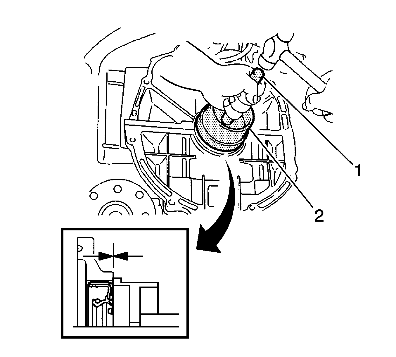
Note: Keep the lip free from foreign matter. Do not tap on the oil seal at an angle.

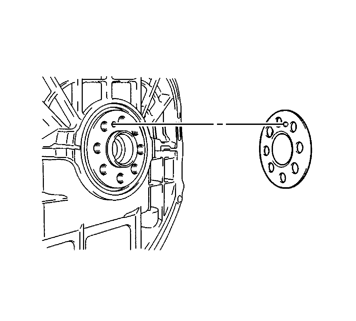
Note: Align the pin of the front spacer with the pin hole of the crankshaft.
Caution: Refer to Fastener Caution in the Preface section.
