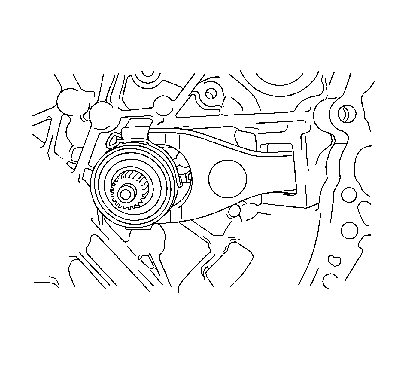
- Remove the clutch release fork sub-assembly together with the clutch release bearing assembly from the manual transaxle case.
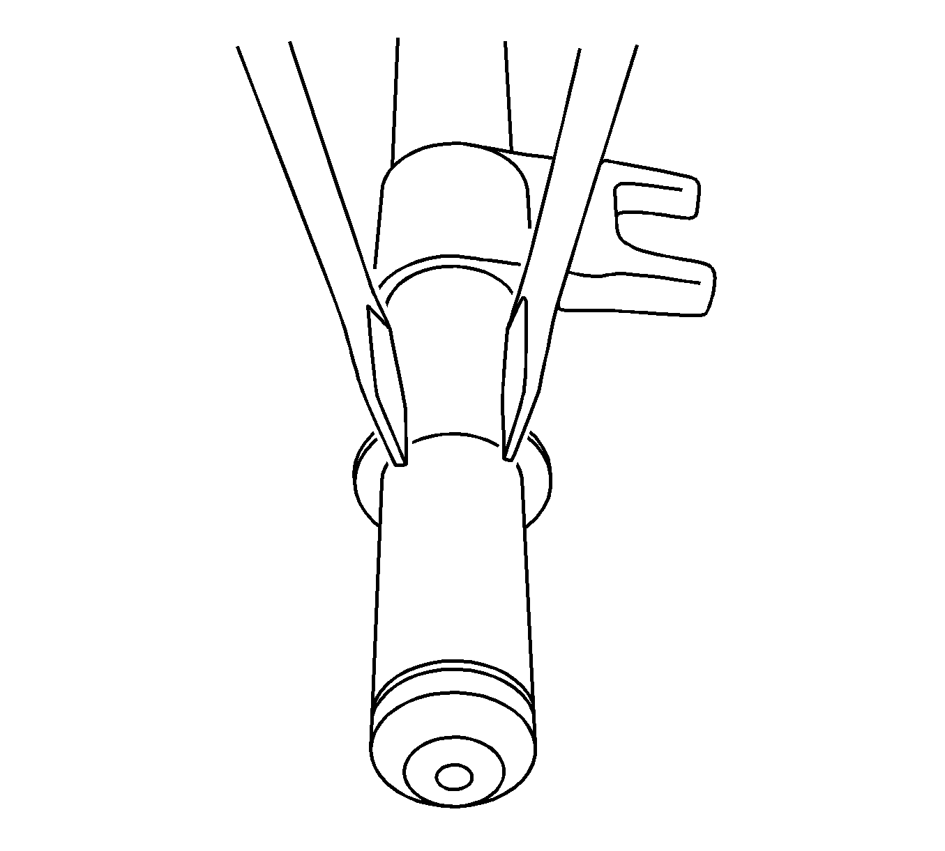
- Remove the clutch release bearing assembly and release bearing hub clip from the clutch release fork sub-assembly.
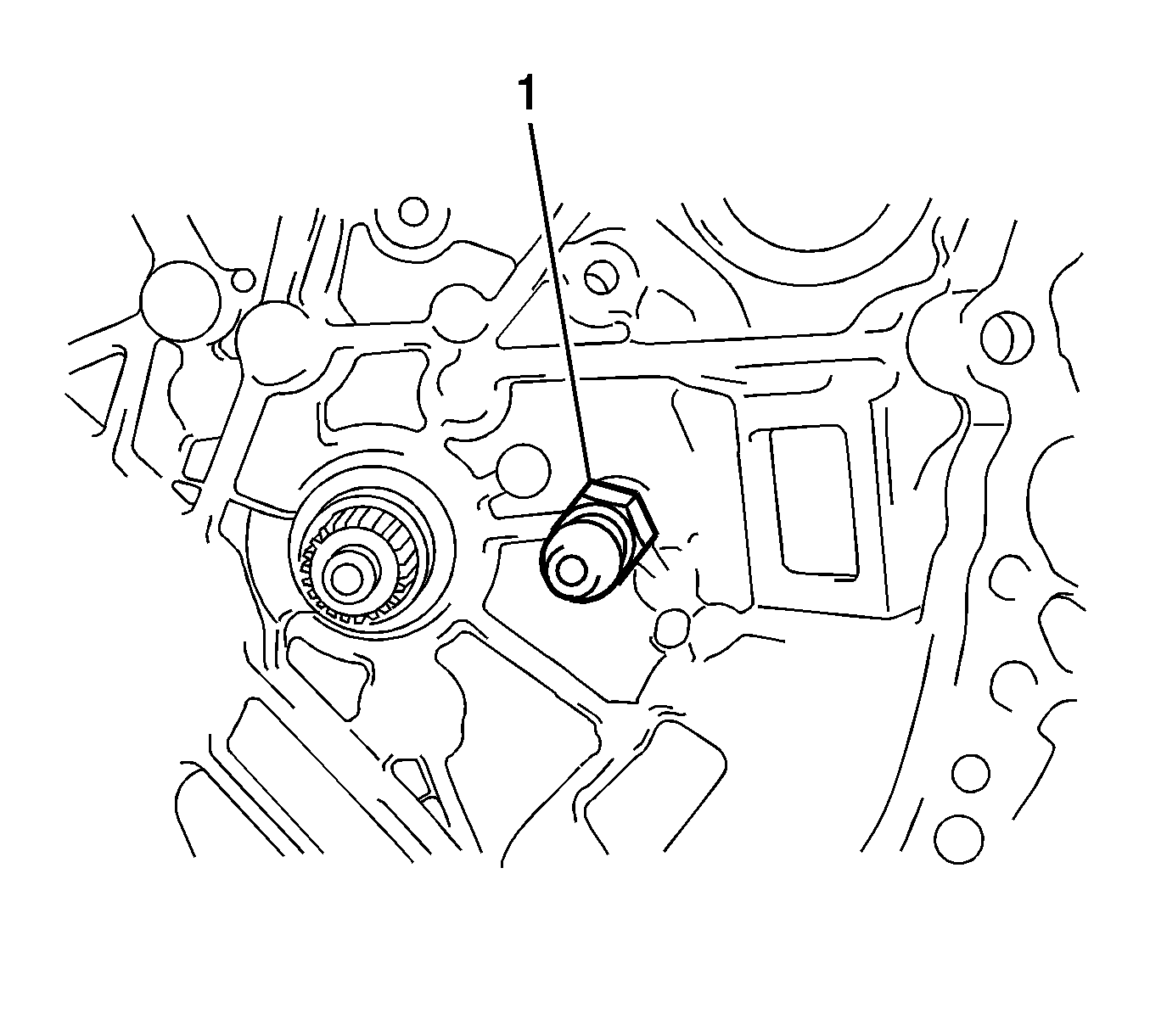
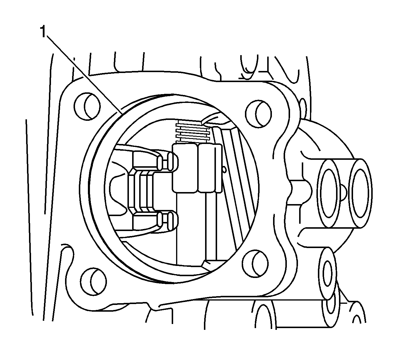
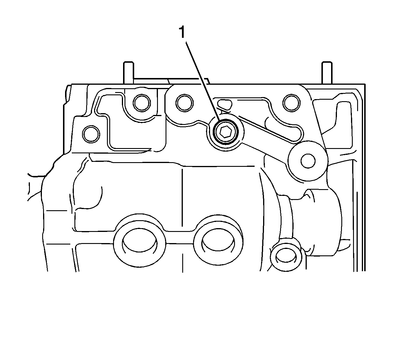
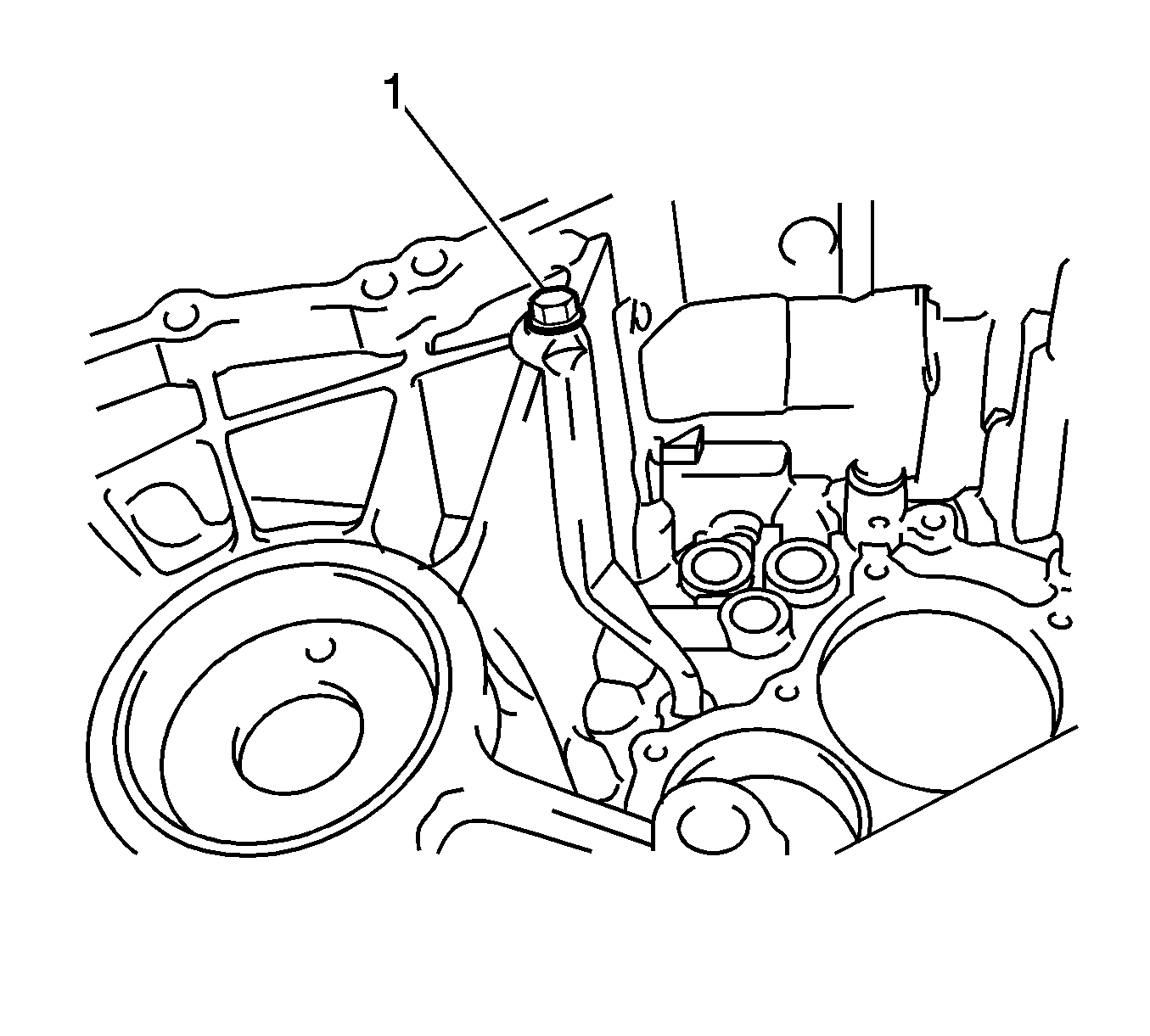
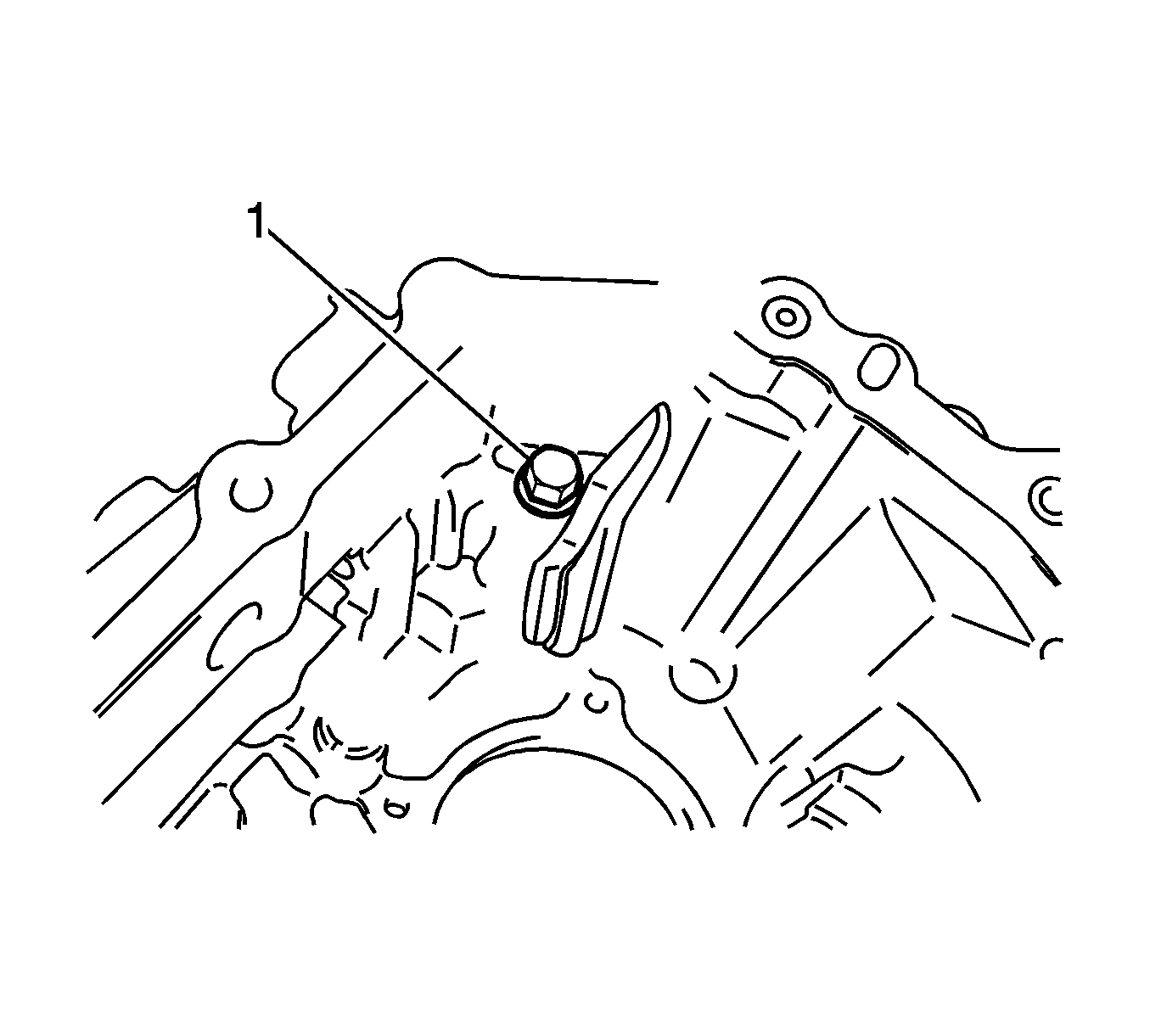
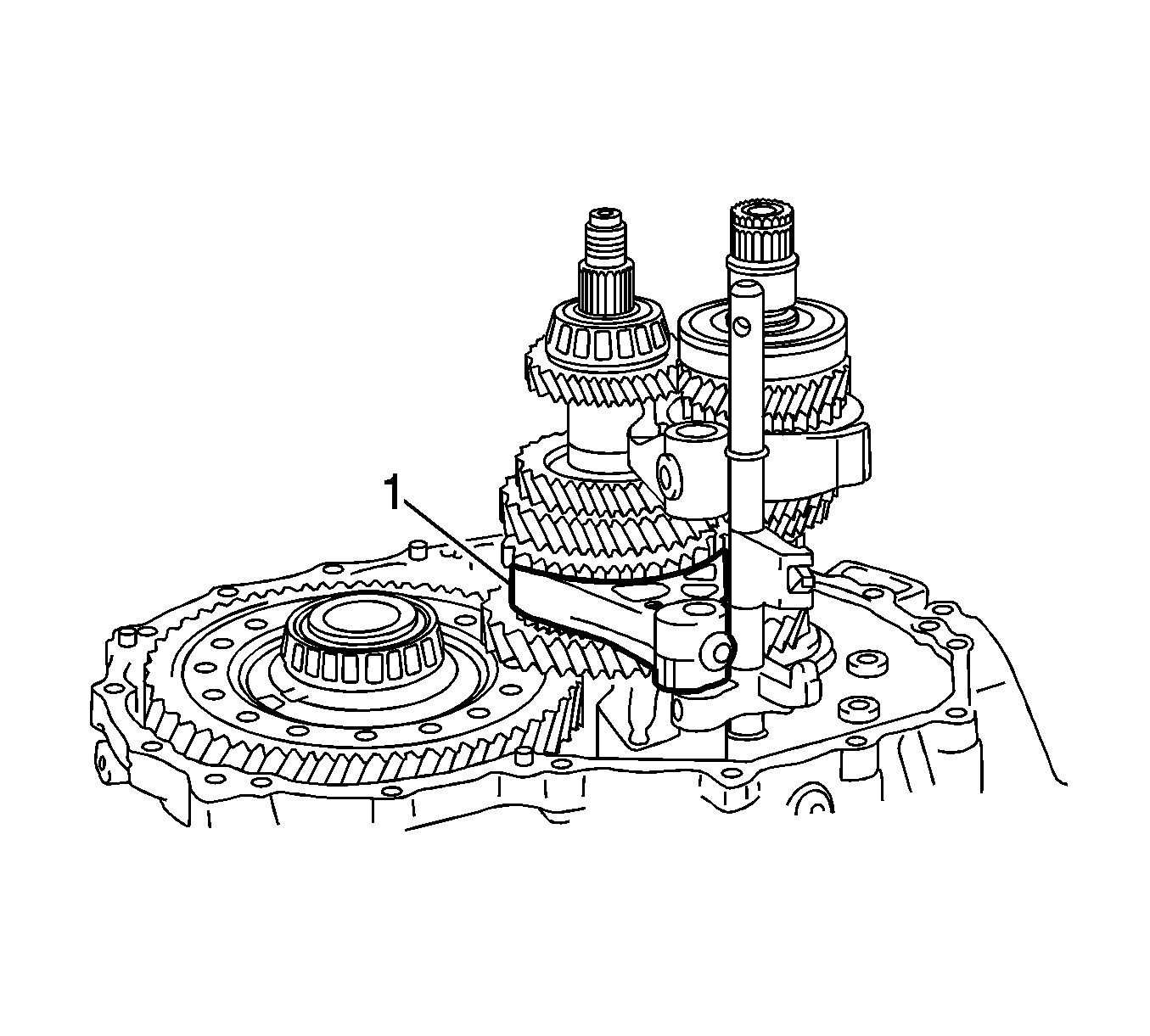
- Remove the release fork support (1) from the manual transaxle case.
- Remove the clutch release fork boot from the manual transaxle case.
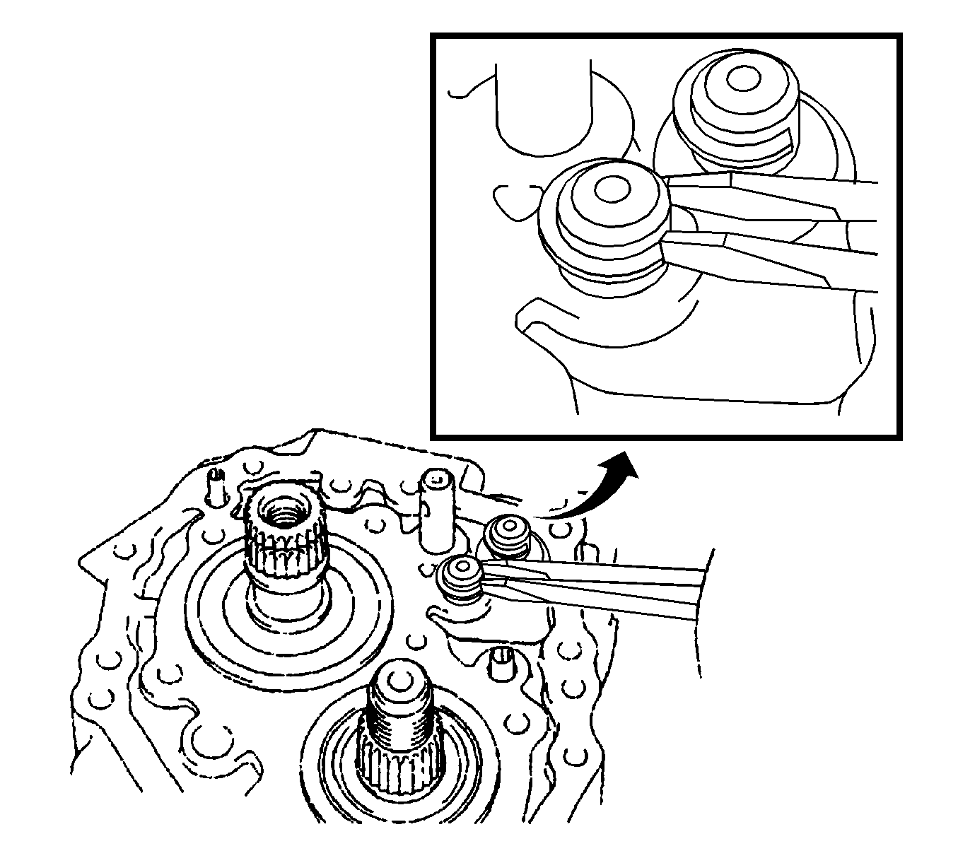
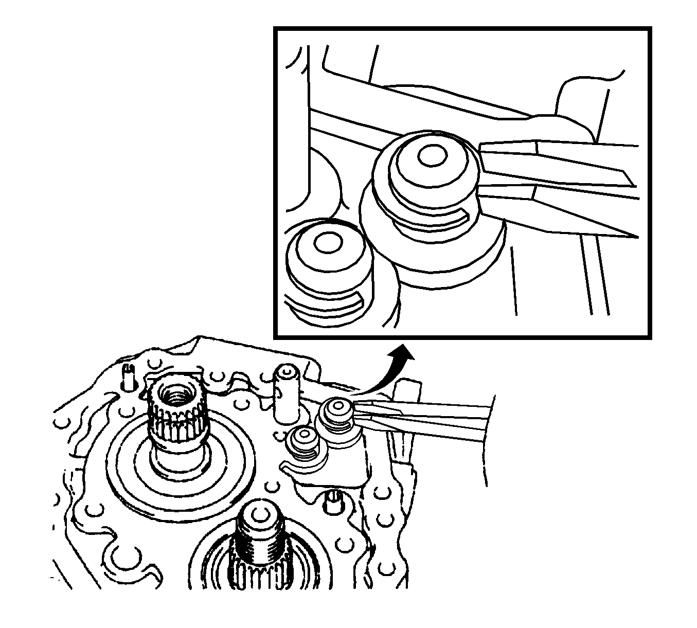
- Remove the bolt and speedometer driven hole cover sub-assembly.
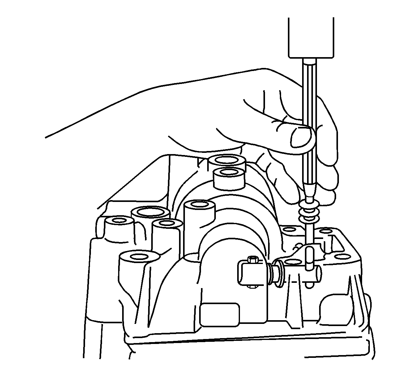
- Remove the O-ring.
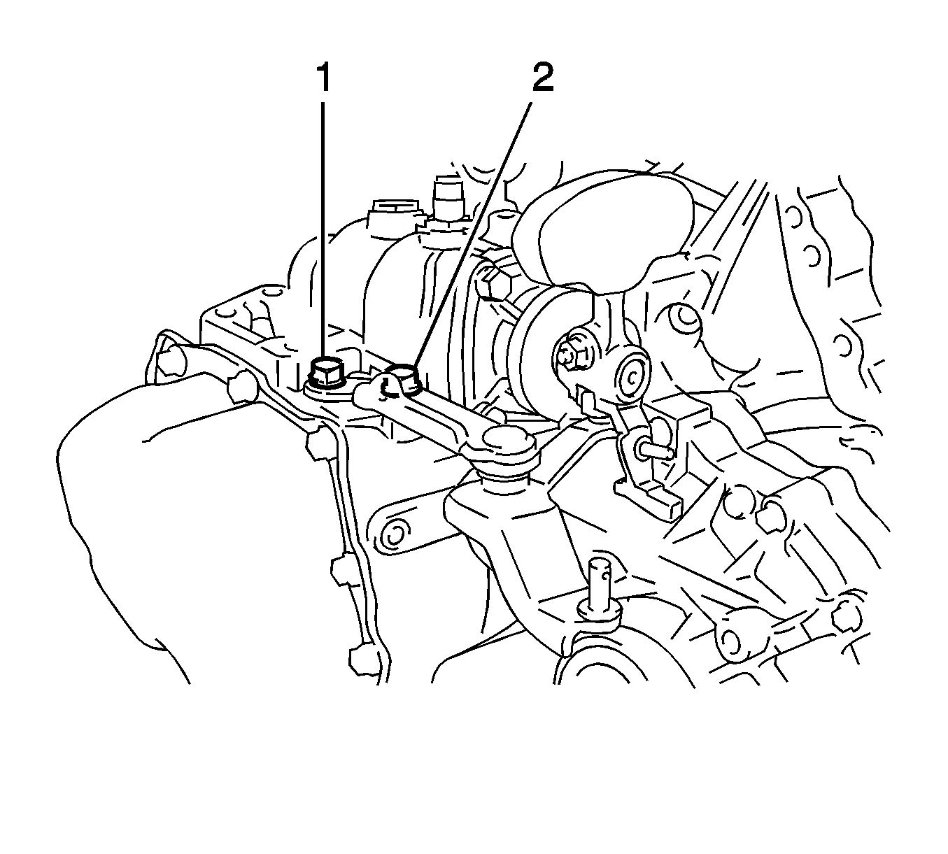
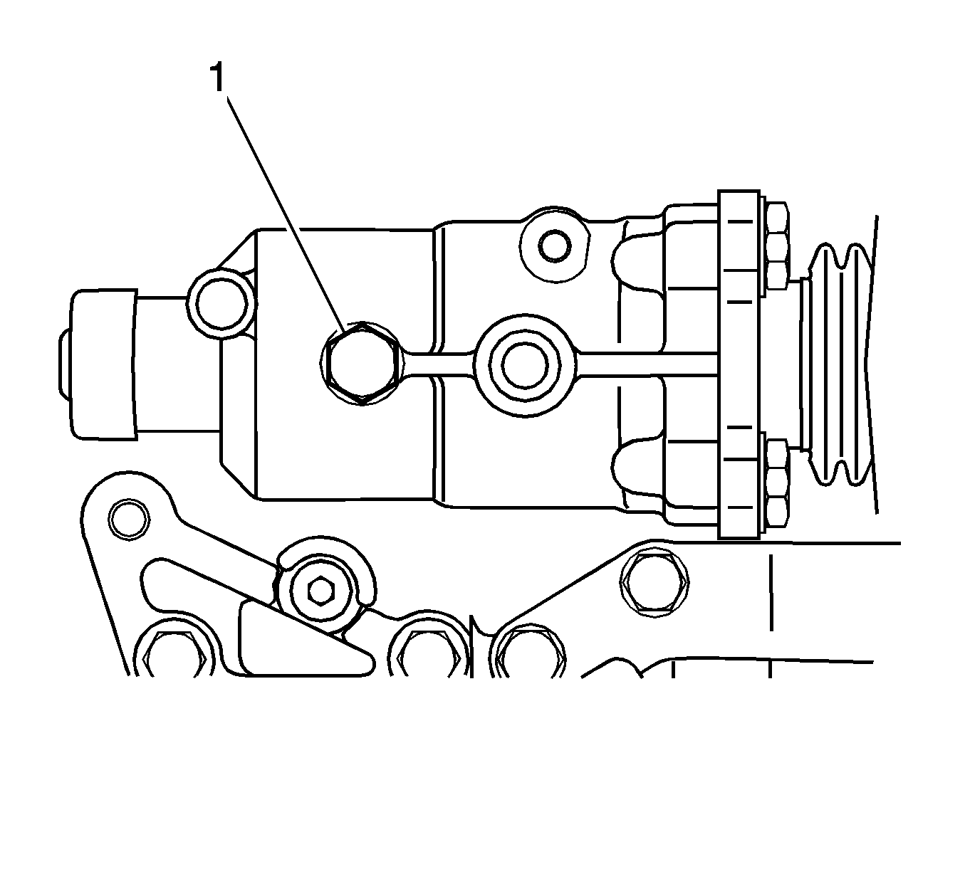
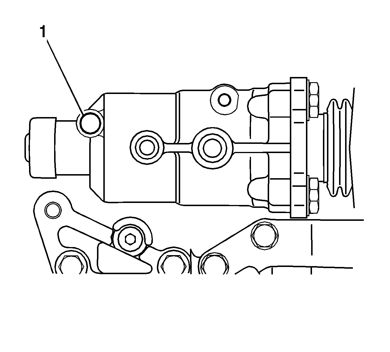
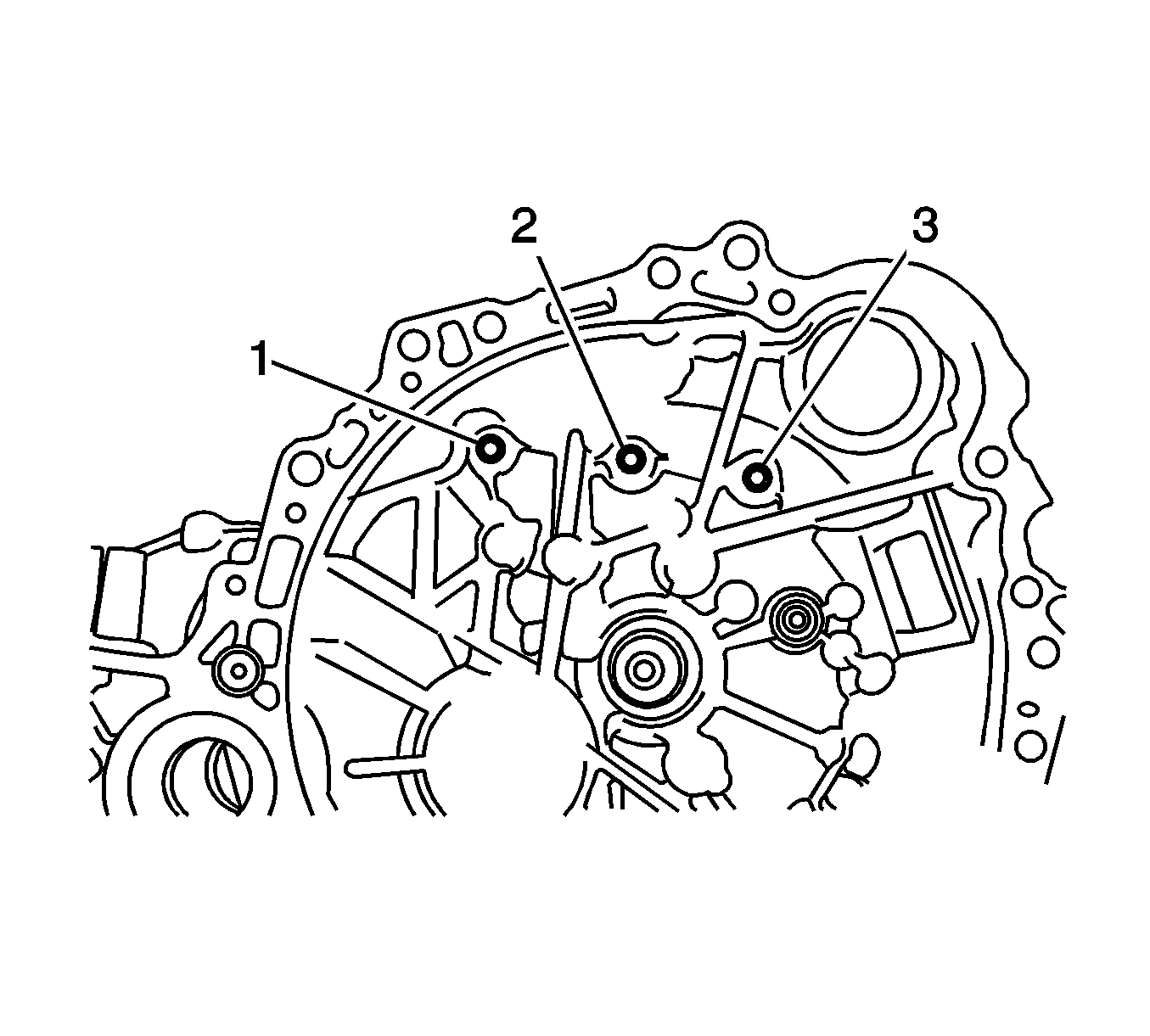
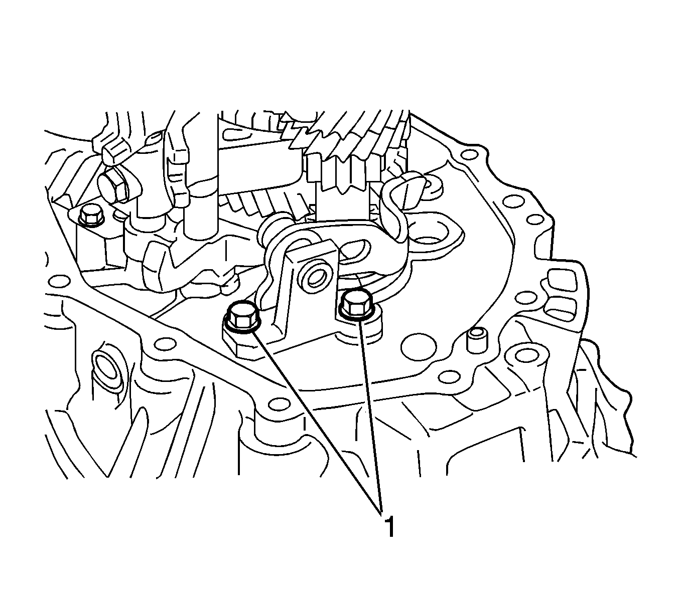
- Remove the bolts (1, 2) and selecting bellcrank assembly from the manual transmission case.
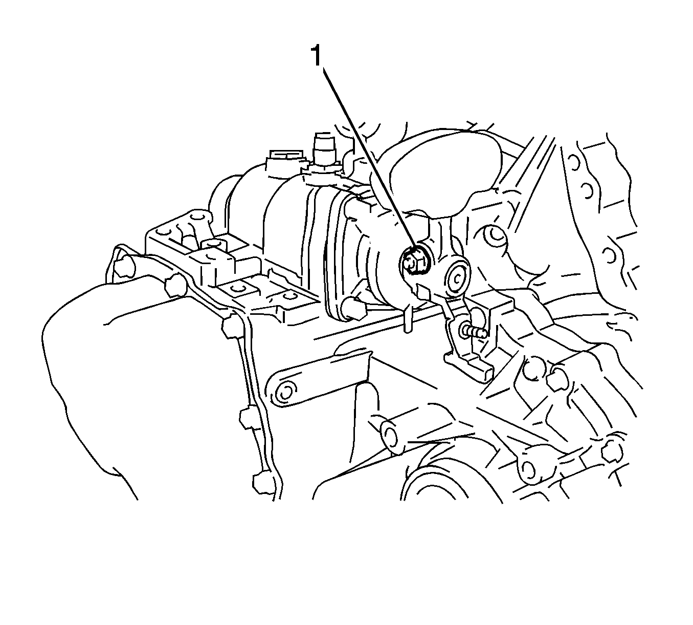
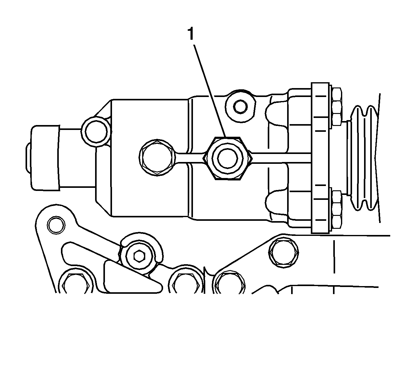
- Remove the nut (1) and spring washer.
- Remove the nut and spring washer.
- Remove the control shift lever.
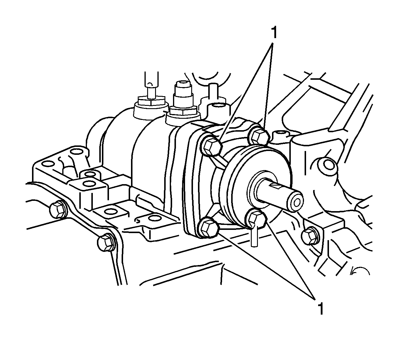
- Remove the bolts (1) and control shaft cover from the manual transmission case.
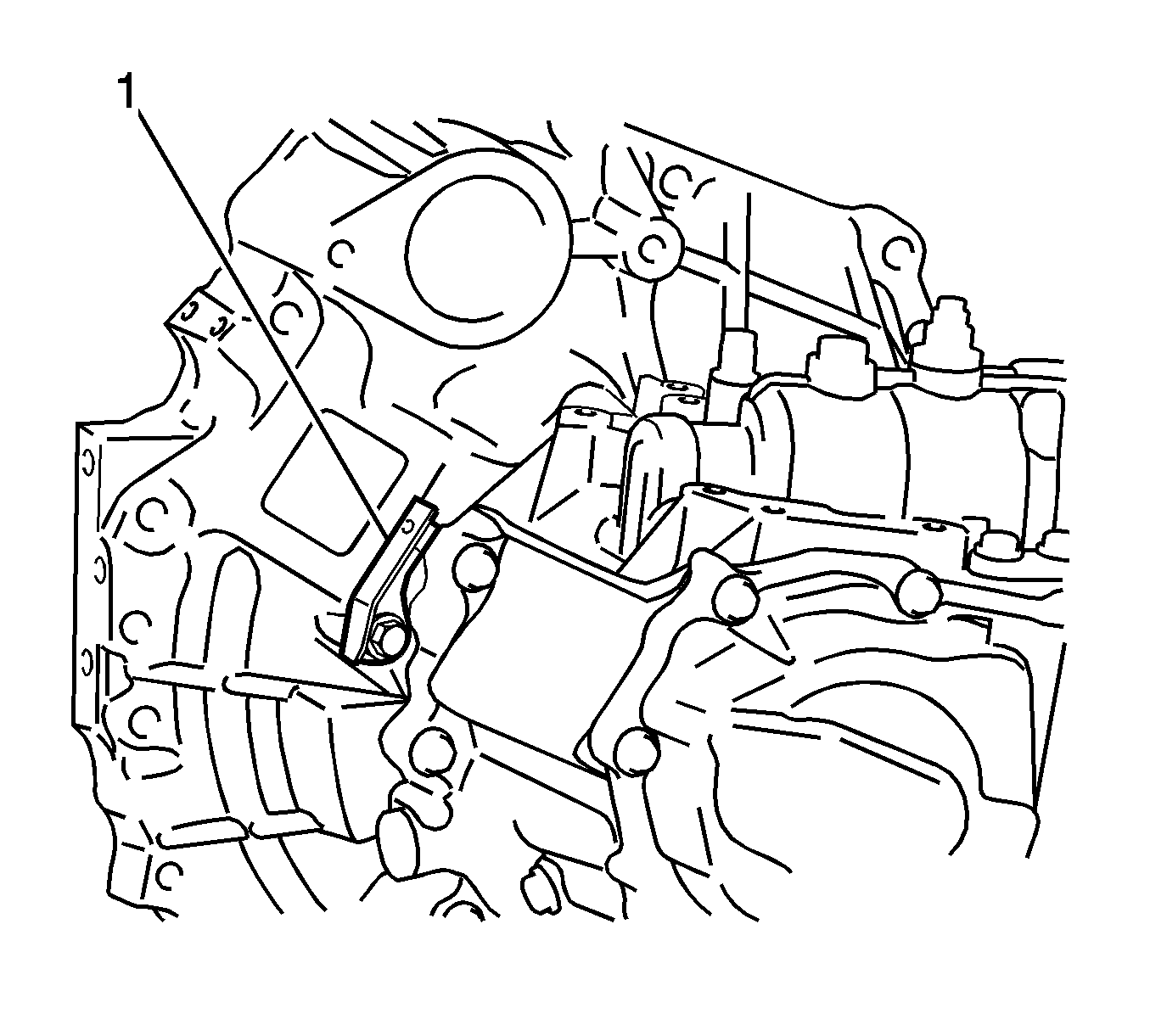
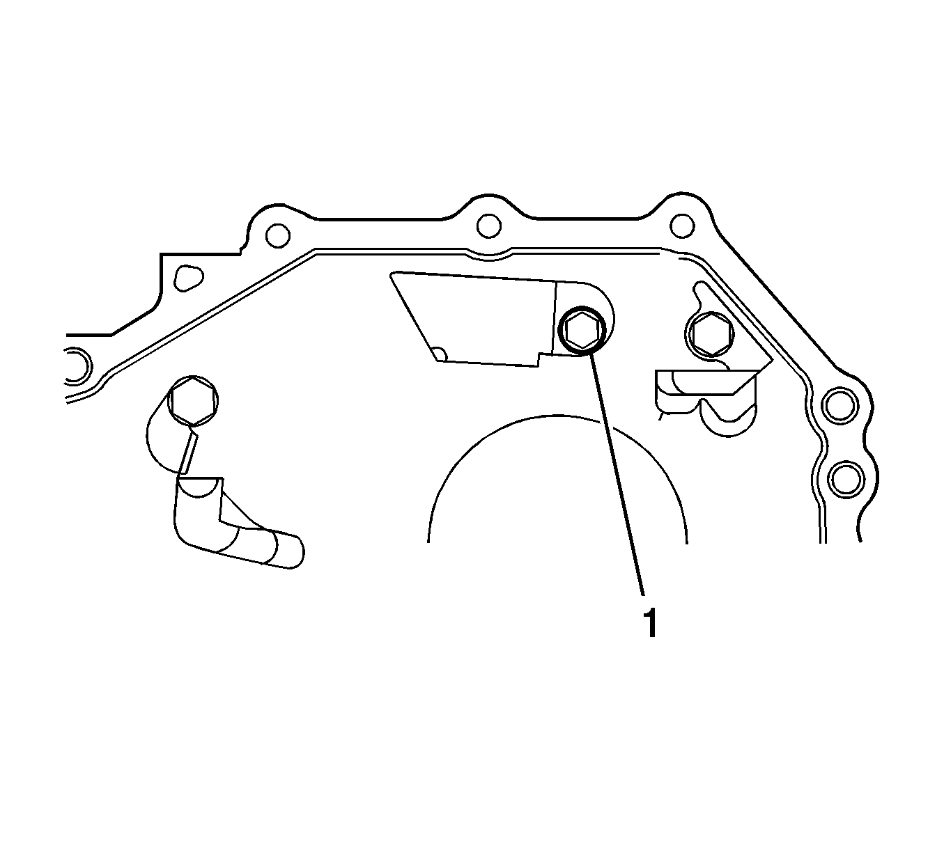
- Remove the bolt and No. 2 clutch tube bracket (1).
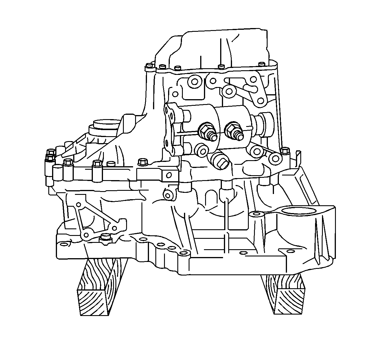
- Place the manual transaxle assembly on wooden blocks.
- Remove the No. 1 lock ball assembly (1) from the manual transmission case.
- Remove the shift gate pin (1) from the manual transmission case.
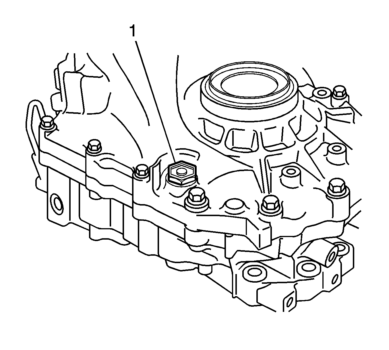
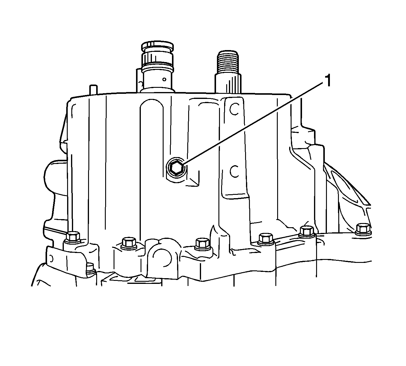
- Remove the manual transmission breather plug (1).
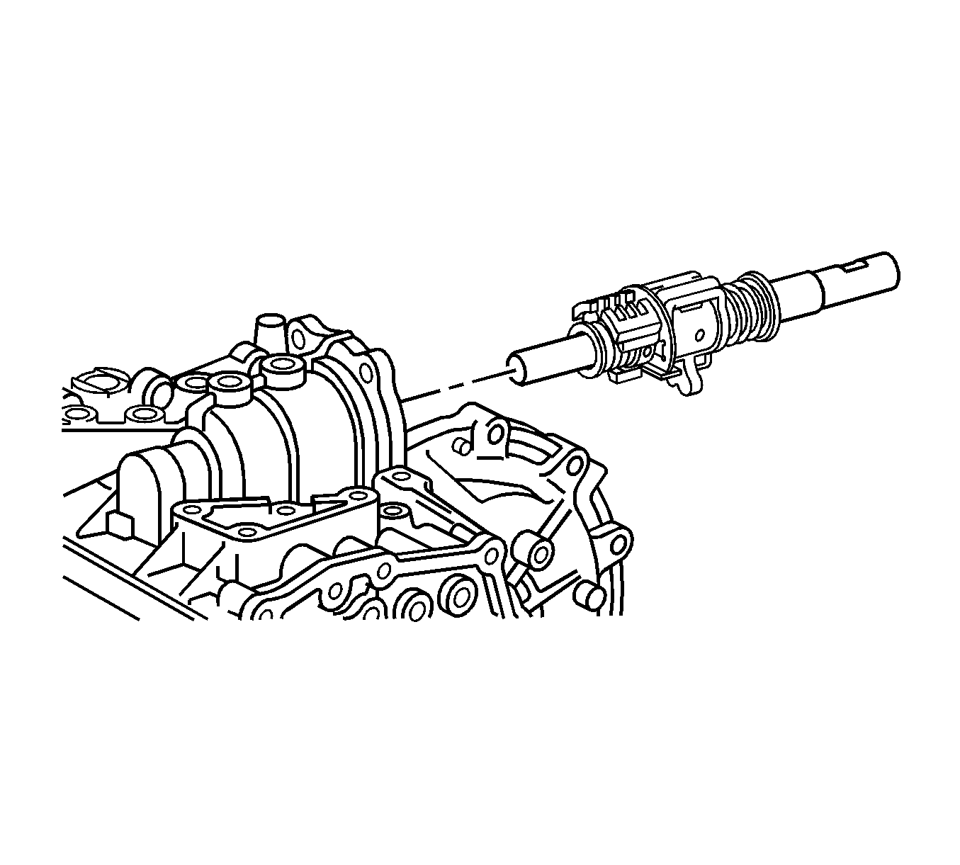
- Remove the shift and select lever shaft assembly from the manual transmission case.
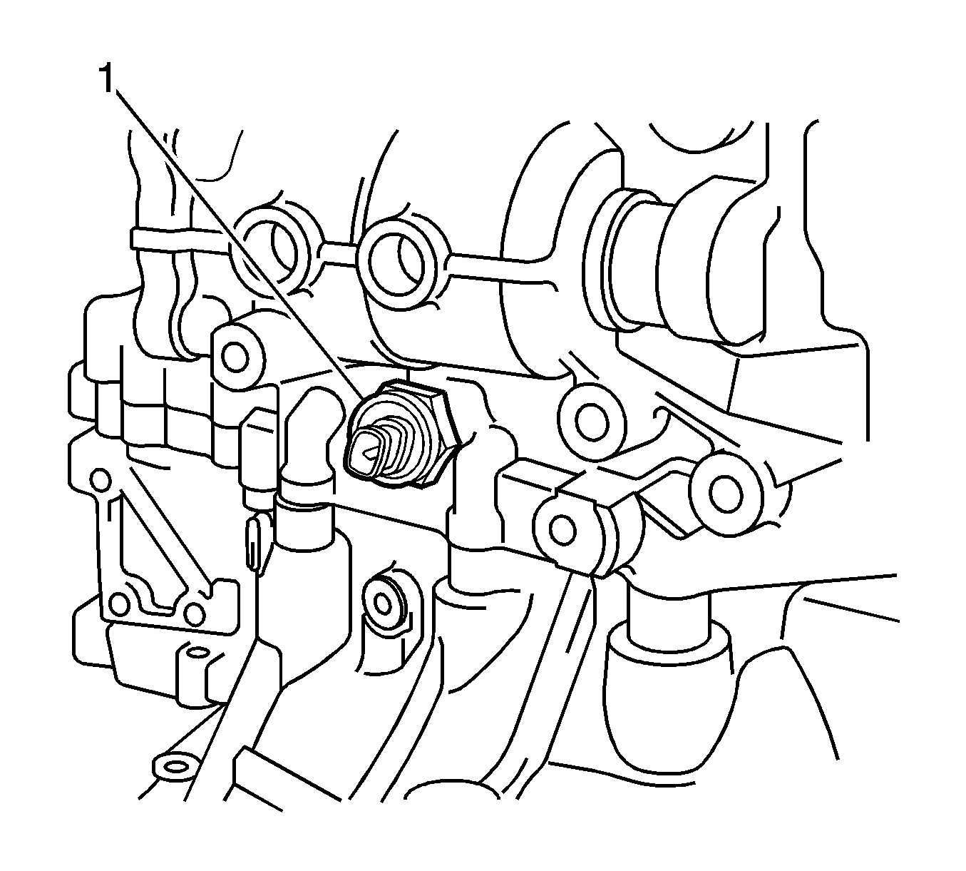
- Remove the back-up light switch assembly (1) and gasket from the manual transmission case.
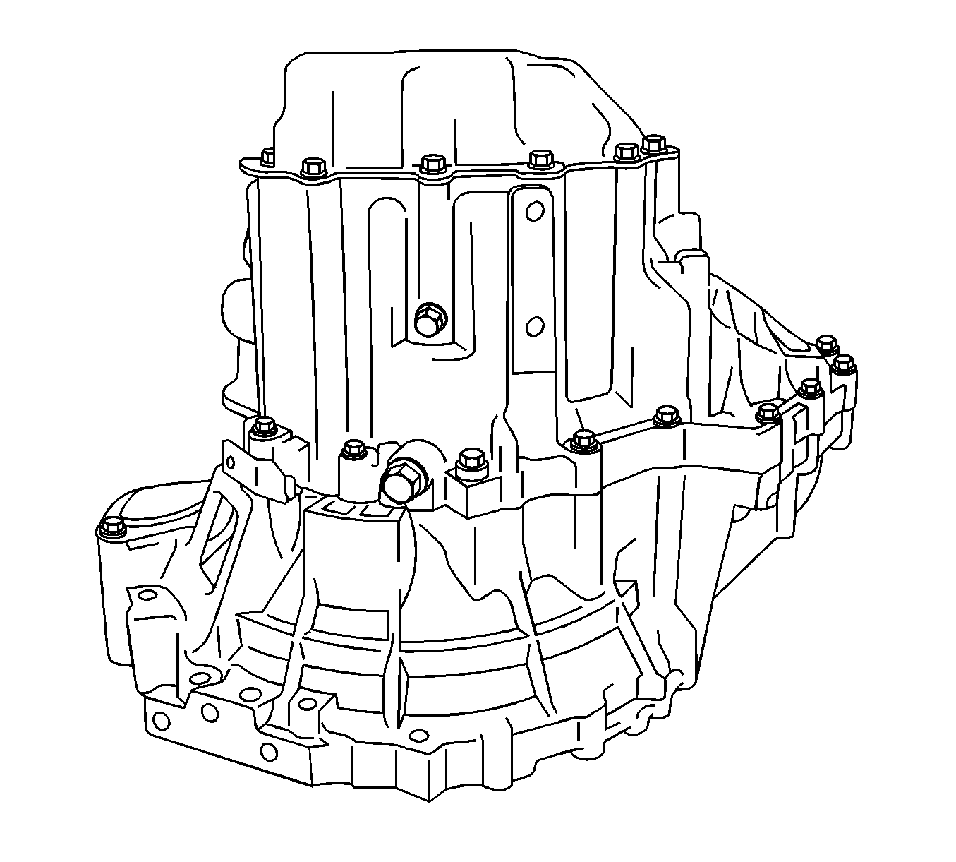
- Remove the manual transmission filler plug and gasket from the manual transmission case.
- Remove the drain plug (1) and gasket from the manual transmission case.
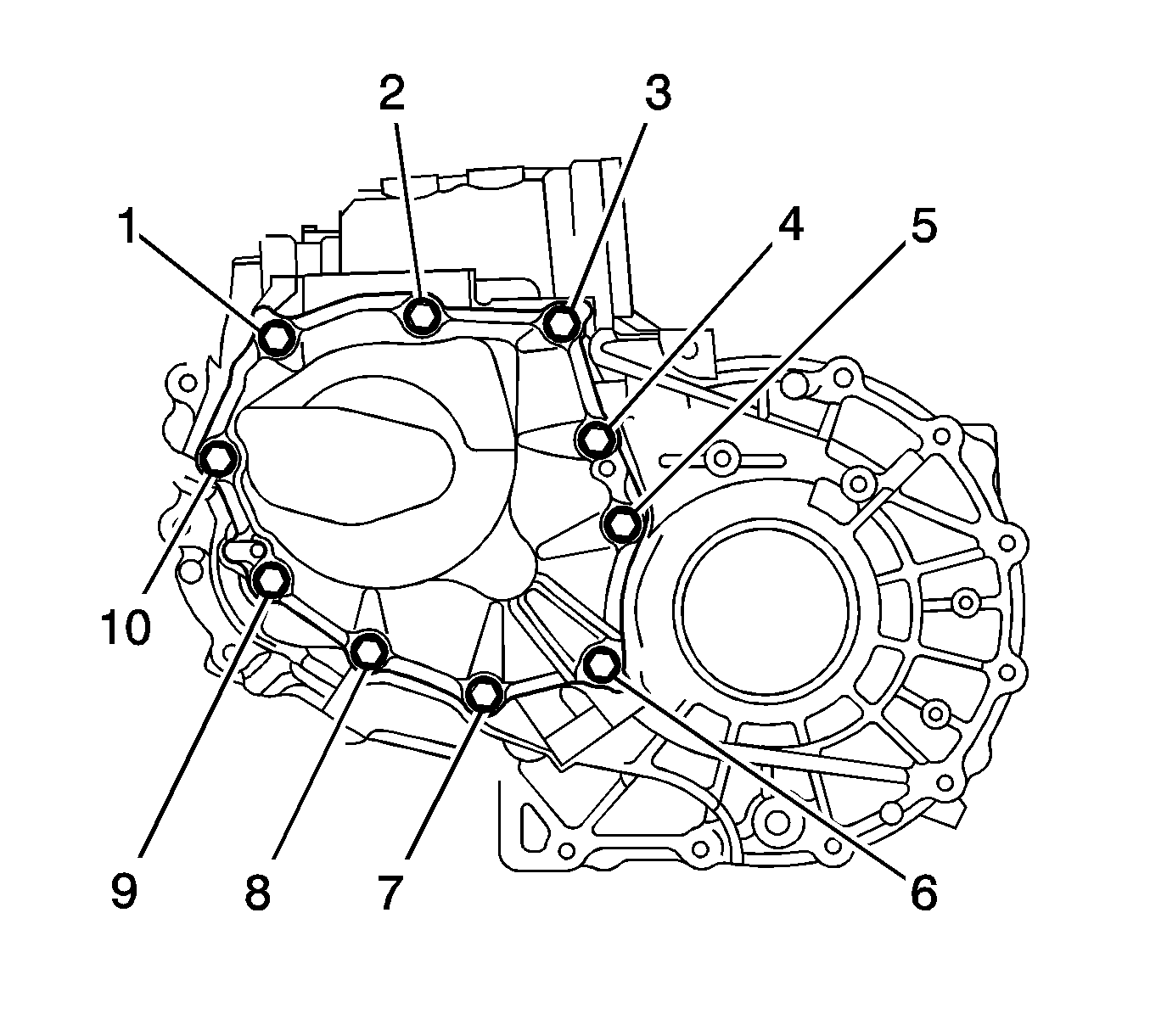
- Remove the bolts (1-10) and manual transmission case cover from the manual transmission case.
- Engage the 1st and 2nd gears (1) simultaneously.
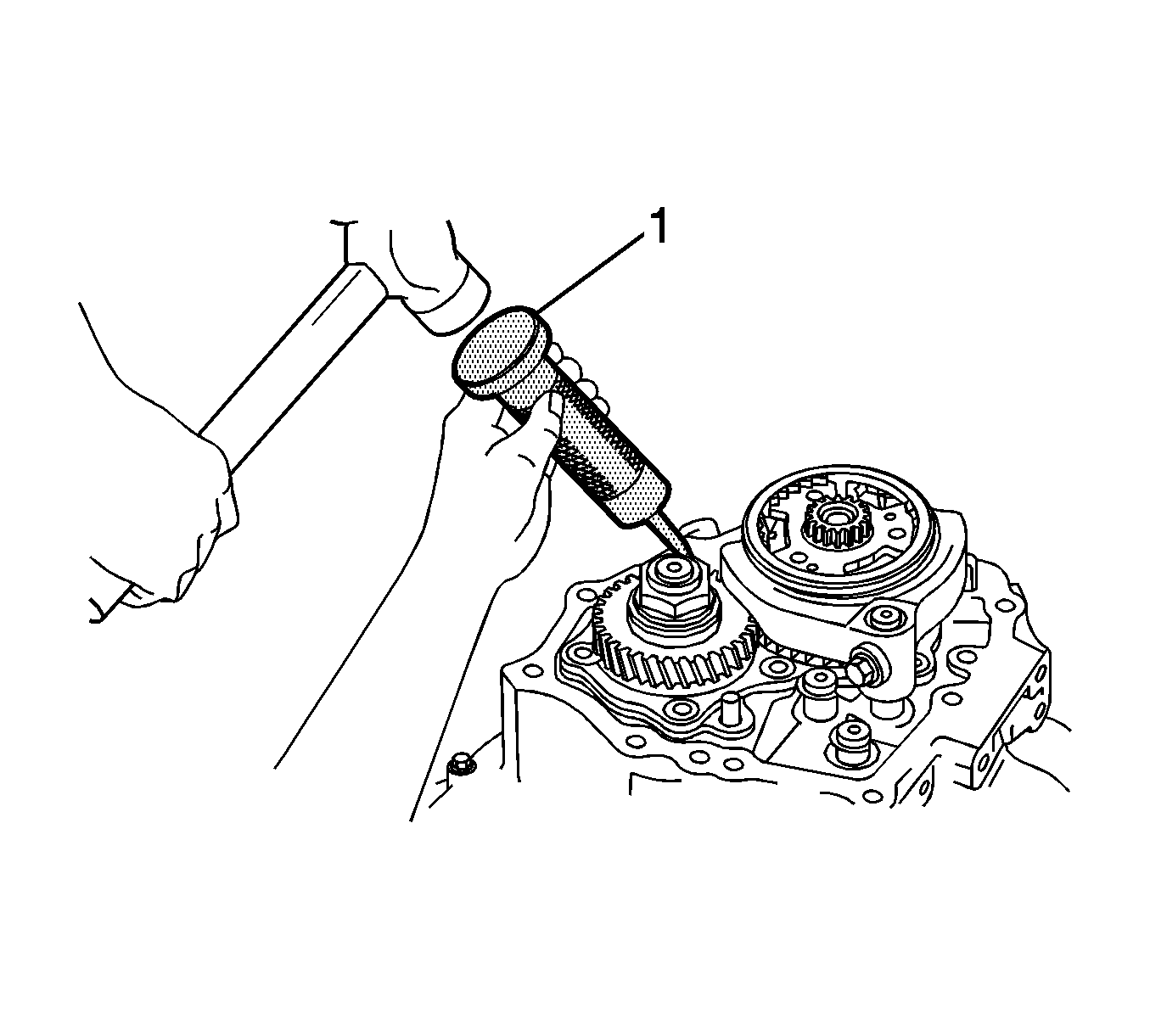
- Using a punch (1) and a hammer, unstake the manual transmission output shaft rear set nut.
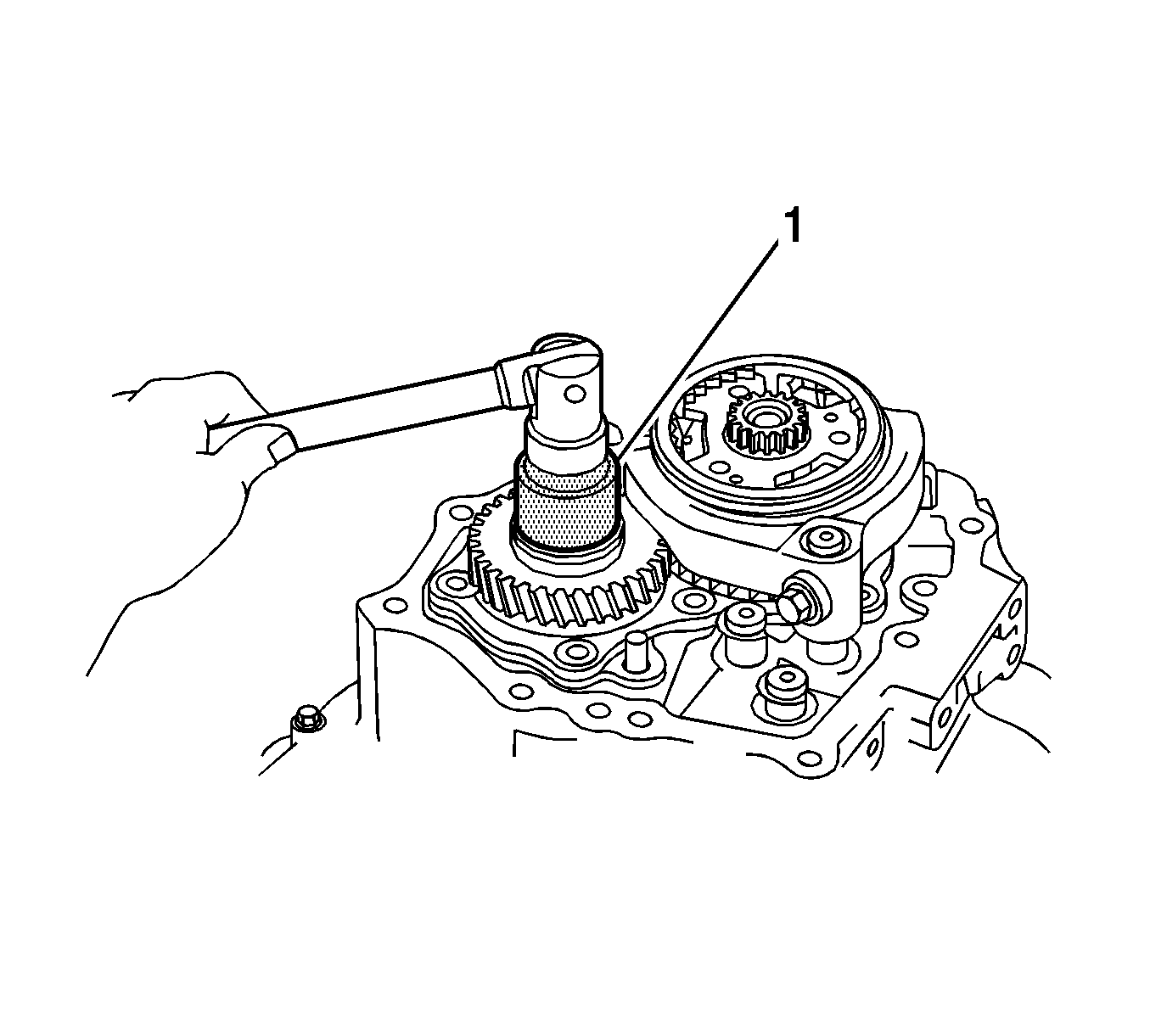
- Remove the manual transmission output shaft rear set nut (1) from the output shaft.
- Disengage the gears.
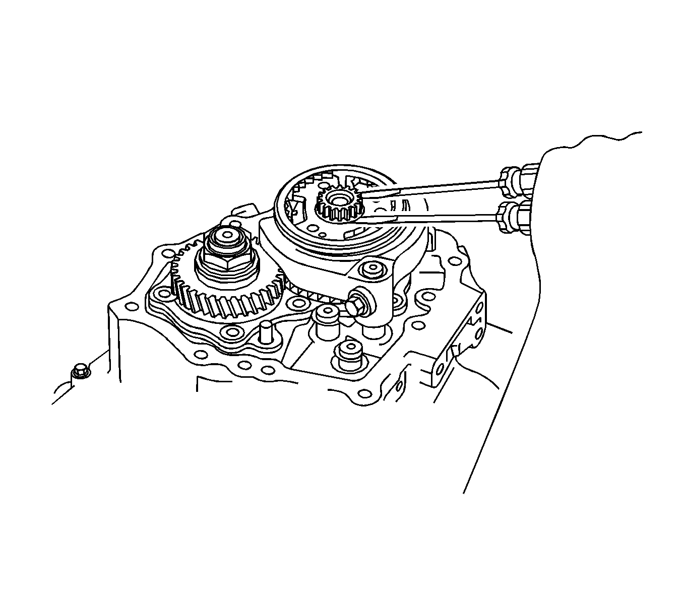
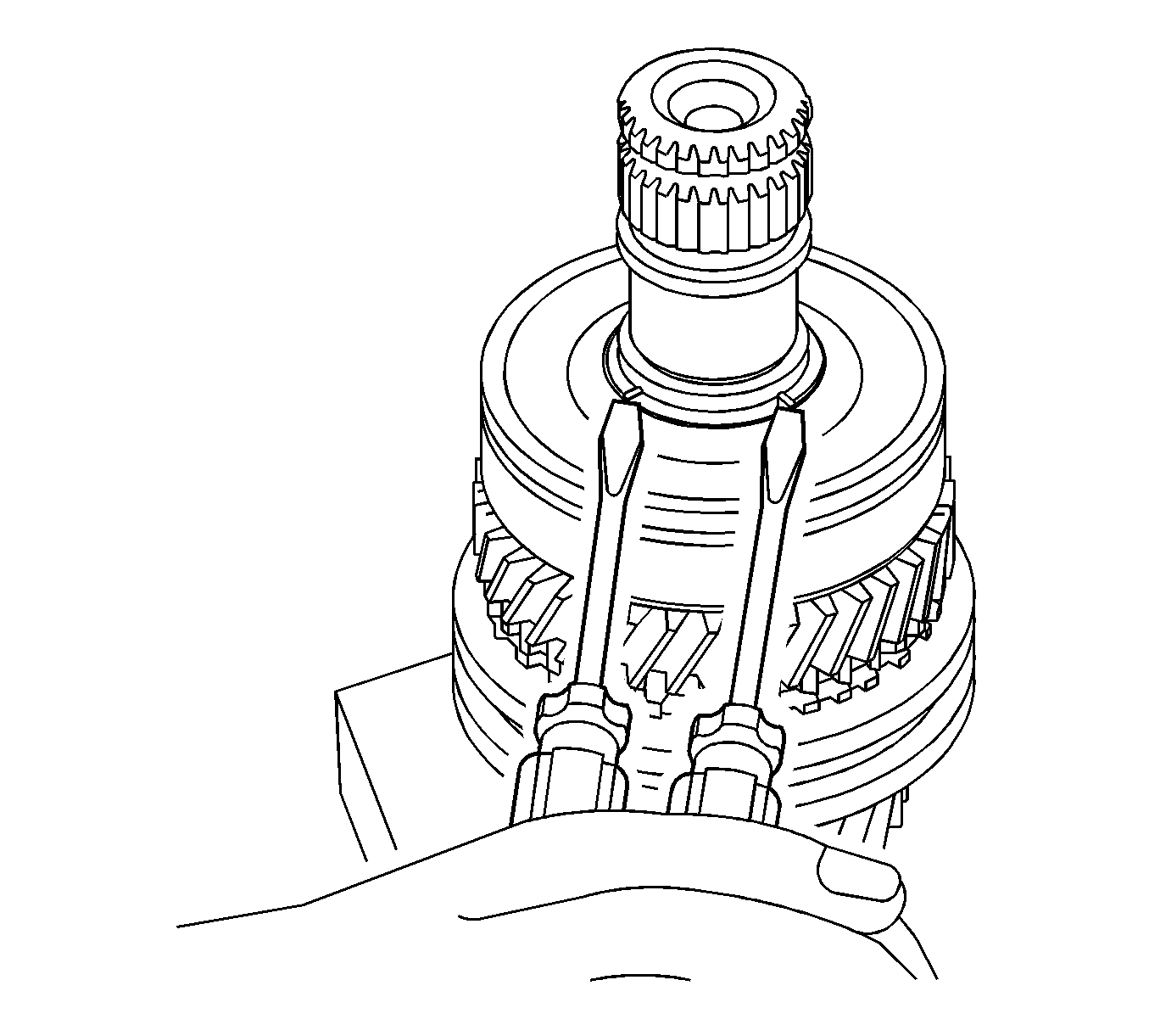
- Using 2 screwdrivers and a hammer, remove the transmission clutch hub No. 3 shaft snap ring from the input shaft.
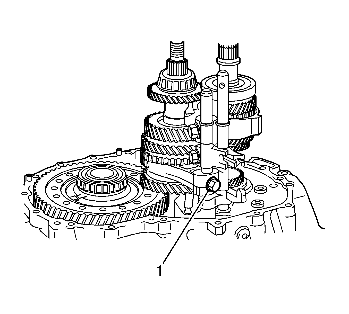
- Remove the shift fork set bolt (1) from the No. 3 gear shift fork.
- Using a suitable puller (1), remove the No. 3 transmission clutch hub and No. 3 gear shift fork from the input shaft.
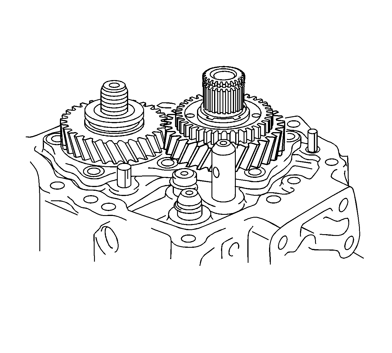
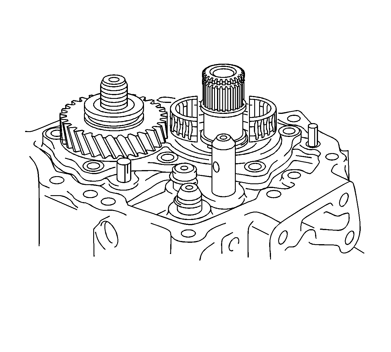
- Remove the 5th gear from the input shaft.
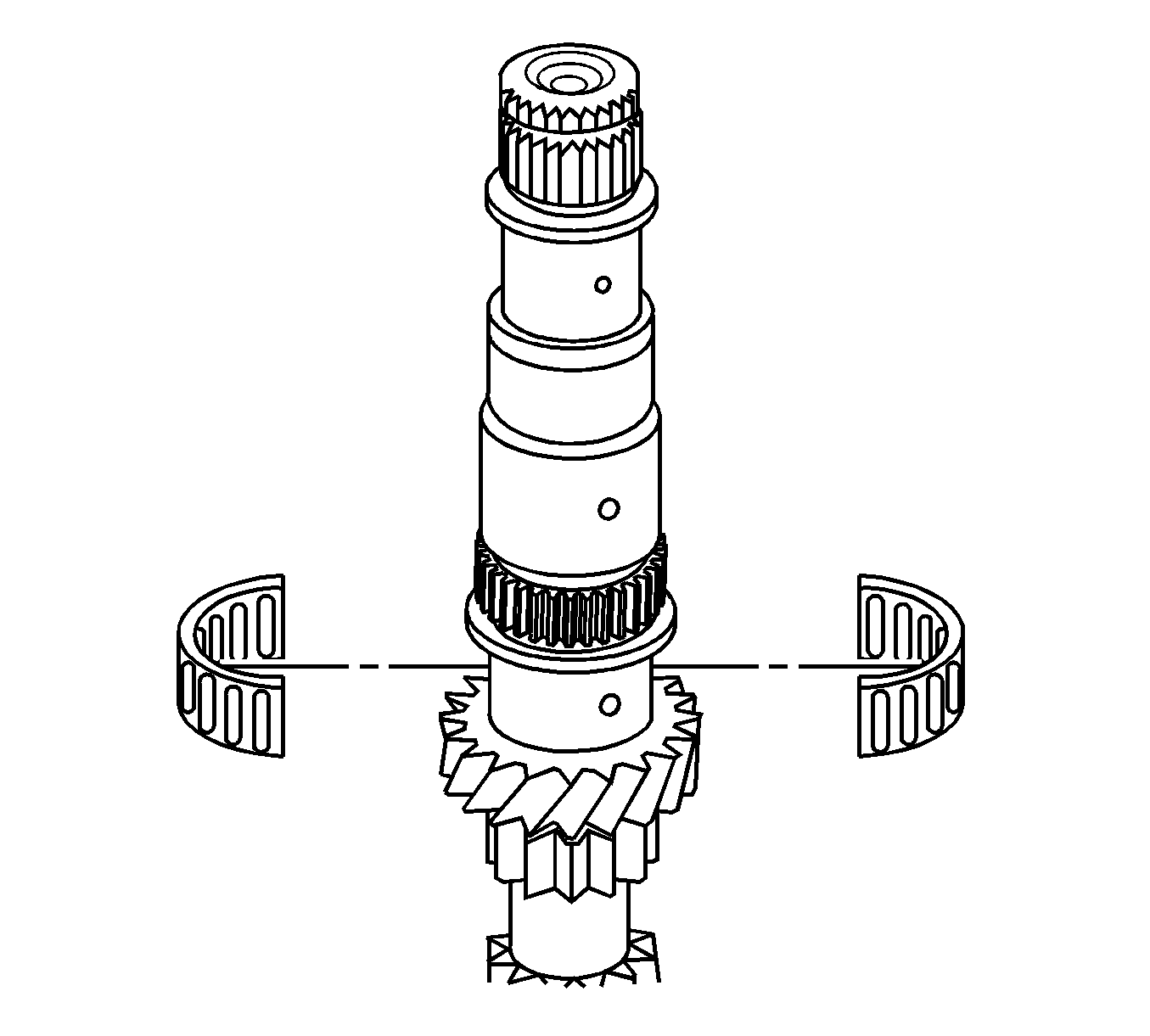
- Remove the 5th gear needle roller bearing from the input shaft.
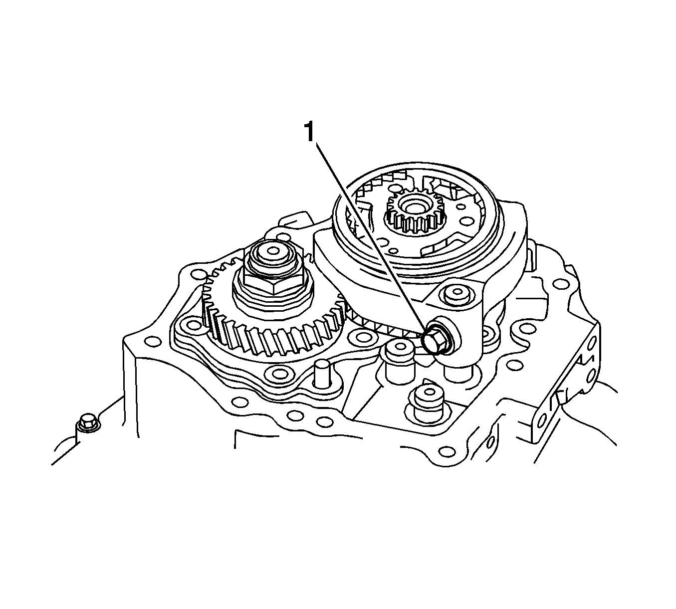
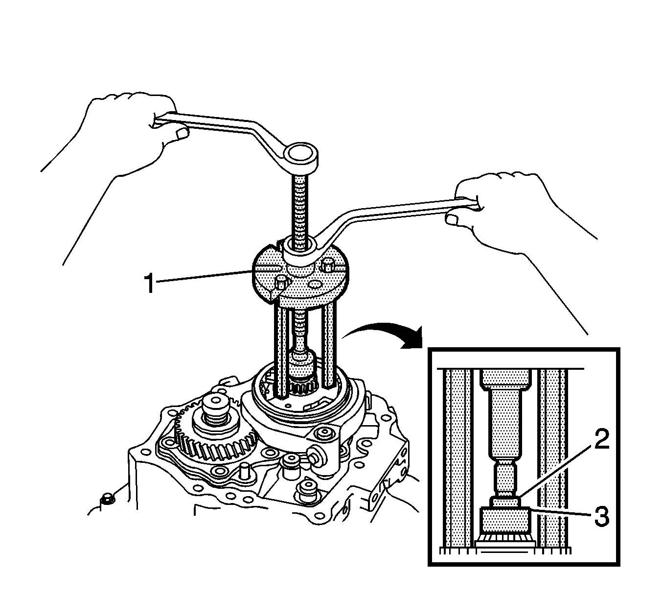
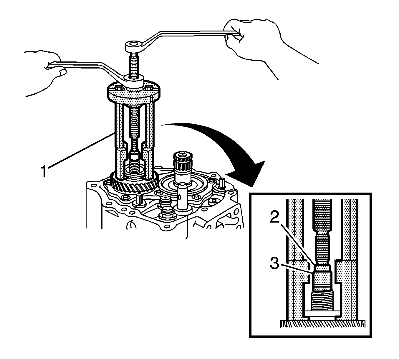
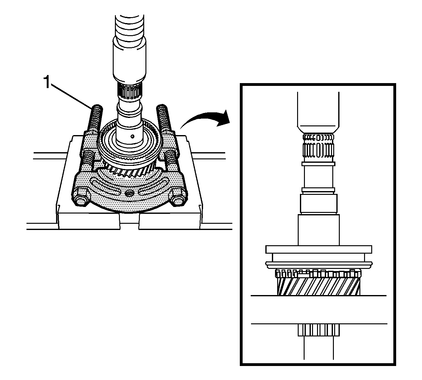
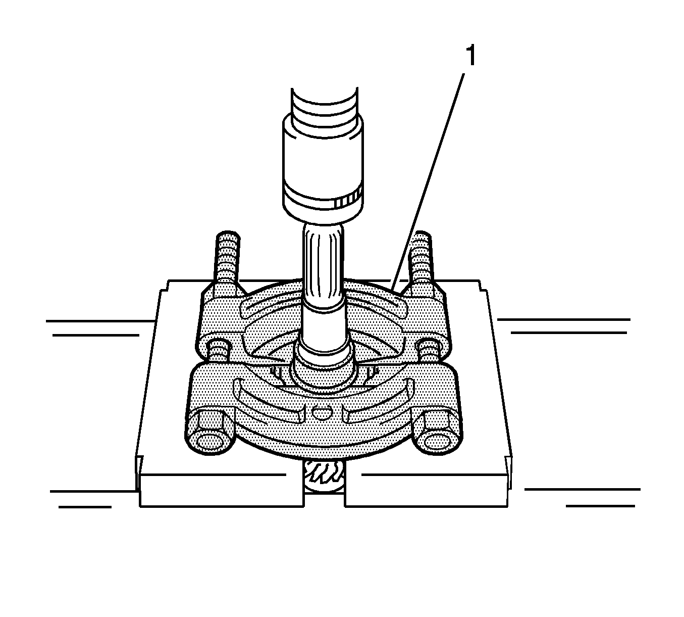
- Using a suitable puller (1), remove the 5th driven gear from the output shaft.
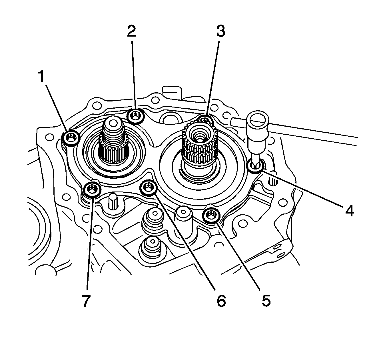
- Remove the bolts (1-7) and rear bearing retainer from the manual transmission case.
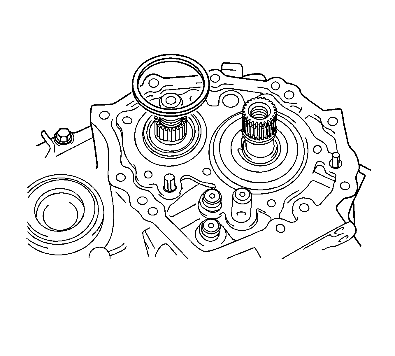
- Remove the output shaft rear bearing shim from the output shaft.
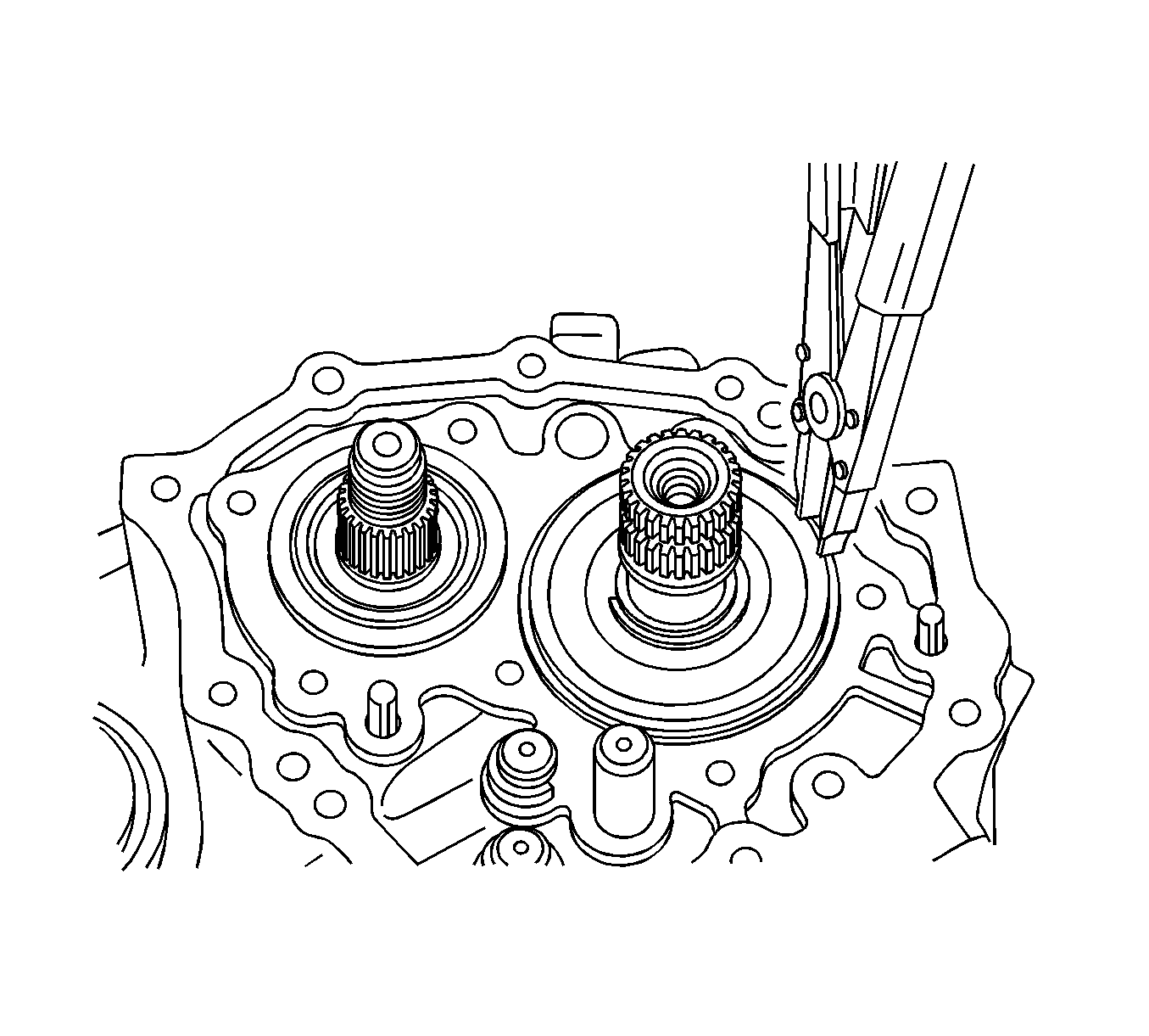
- Remove the input shaft rear bearing shaft snap ring from the input shaft.
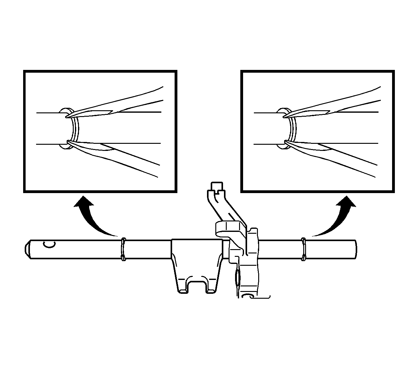
- Remove the shift fork shaft snap ring from the No. 1 gear shift fork shaft.
- Using 2 screwdrivers and a hammer, remove the shift fork shaft snap ring from the No. 2 gear shift fork shaft.
- Remove the reverse idler gear shaft bolt (1) and gasket.
- Remove the bolts (1-3) from the manual transaxle case.
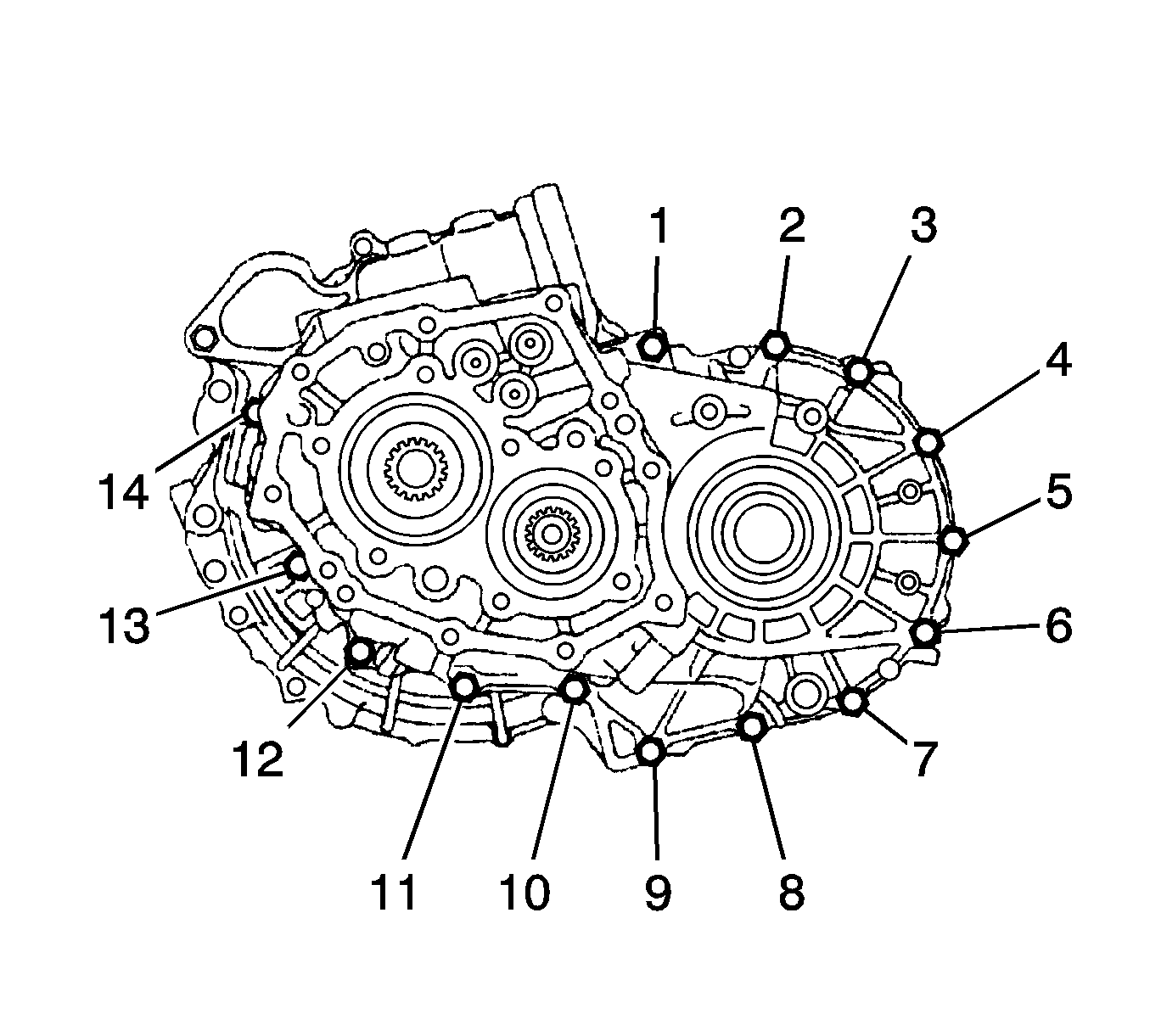
- Remove the bolts (1-14) from the manual transmission case.
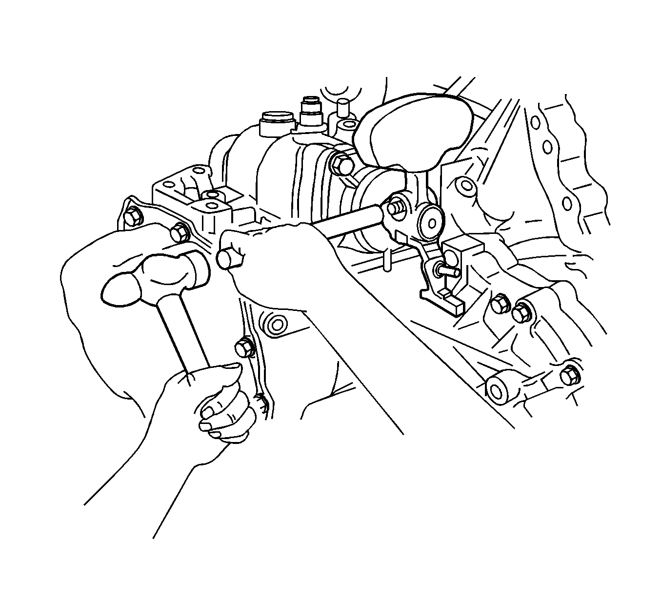
- Tapping with a plastic hammer, remove the manual transmission case.
- Remove the reverse restrict pin plug (1) from the manual transmission case.
- Using a pin punch and hammer, remove the slotted pin.
- Remove the bolt (1), transmission oil baffle and reverse restrict pin assembly.
- Remove the bolt (1) and No. 2 oil receiver pipe from the manual transmission case.
- Remove the bolt (1) and No. 1 oil receiver pipe from the manual transmission case.
- Remove the transmission magnet from the manual transaxle case.
- Remove the reverse idler gear sub-assembly from the manual transaxle case.
- Remove the reverse gear and reverse idler thrust washer from the reverse idler gear shaft.
- Remove the bolts (1) and reverse shift arm bracket assembly from the manual transaxle case.
- Remove the shift fork set bolt (1) from the No. 1 gear shift fork.
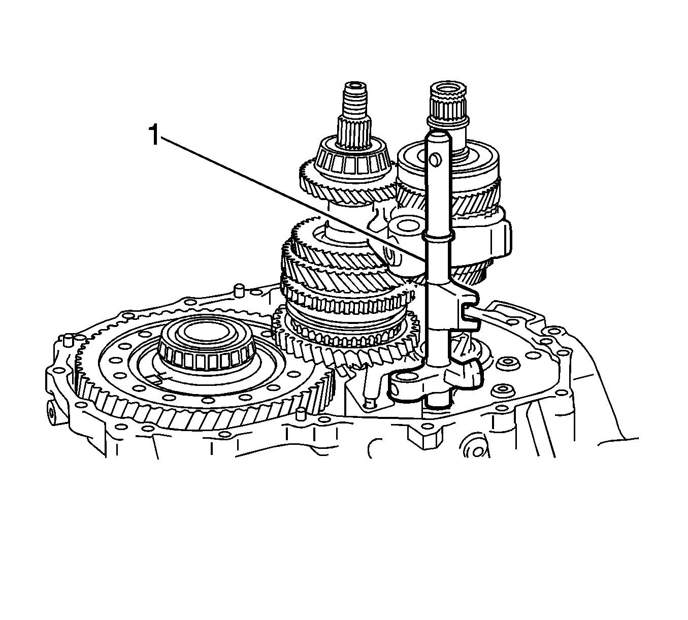
- Pull out the No. 1 gear shift fork shaft (1) while pulling up the No. 3 gear shift fork shaft.
- Remove the shift fork shaft snap ring from the No. 1 gear shift fork shaft.
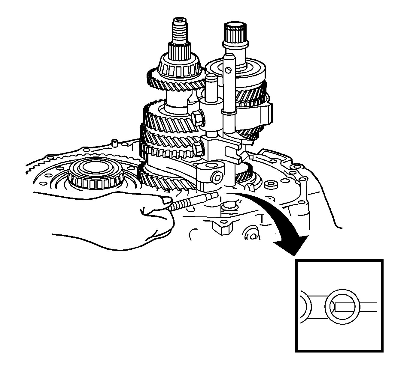
- Using a magnetic pick-up tool, remove the reverse shift fork roller from the reverse shift fork.
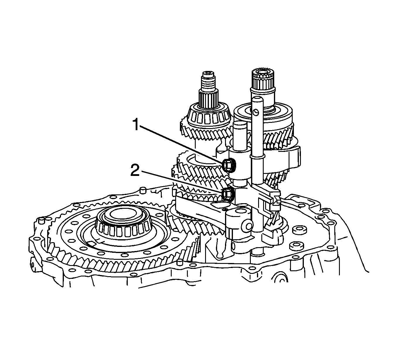
- Remove the shift fork set bolt (1) and shift head set bolt (2) from the No. 2 gear shift fork and No. 1 gear shift head.
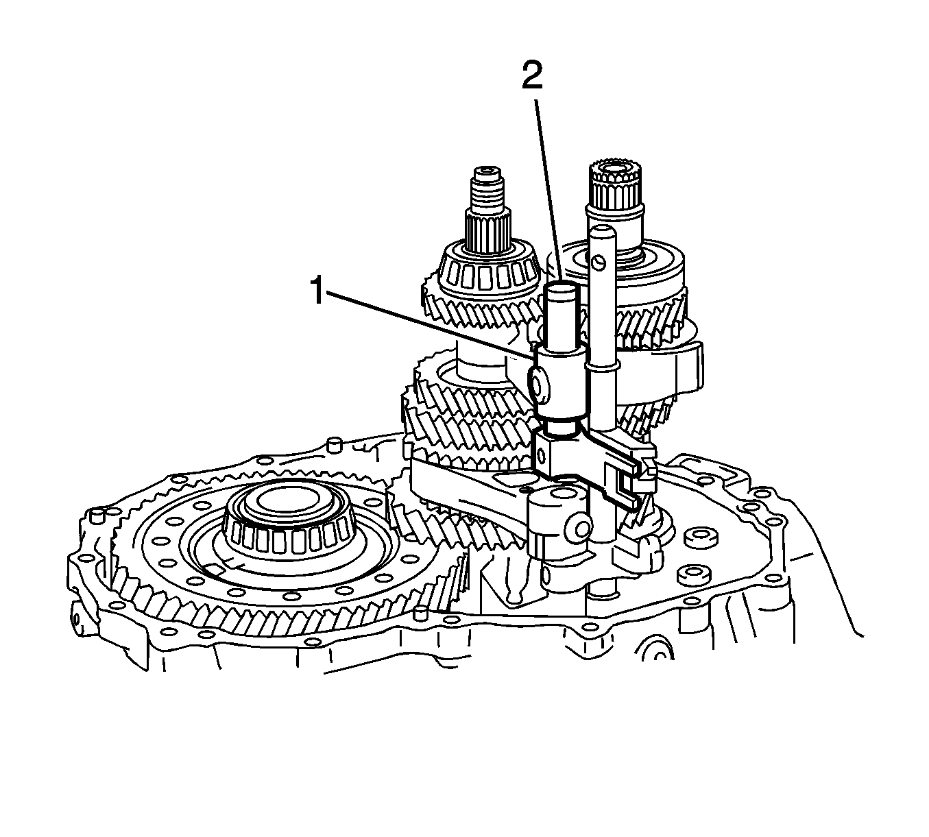
- Remove the No. 2 gear shift fork (2) shaft and No. 1 gear shift head (1) from the manual transaxle case.
- Remove the No. 1 gear shift fork (1).
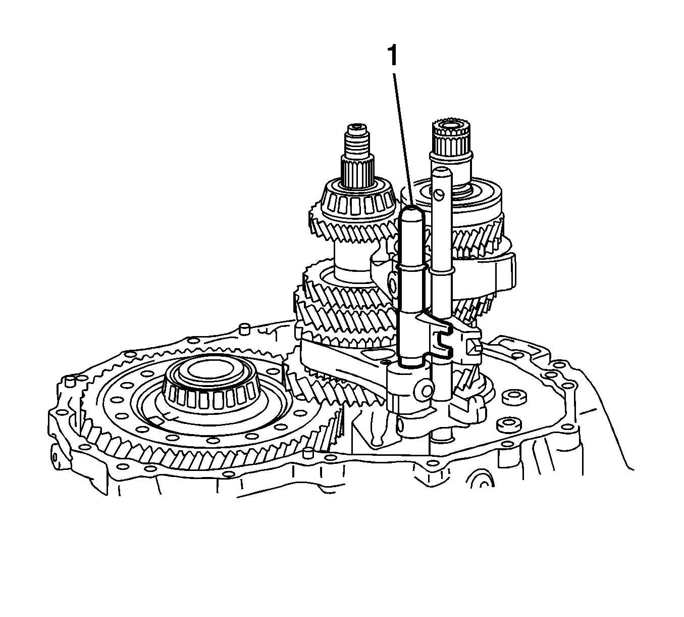
- Remove the No. 3 gear shift fork shaft (1) from the manual transaxle case.
- Using 2 screwdrivers and a hammer, remove the 2 shift fork shaft snap rings from the No. 3 gear shift fork shaft.
- Remove the reverse shift fork from the No. 3 gear shift fork shaft.
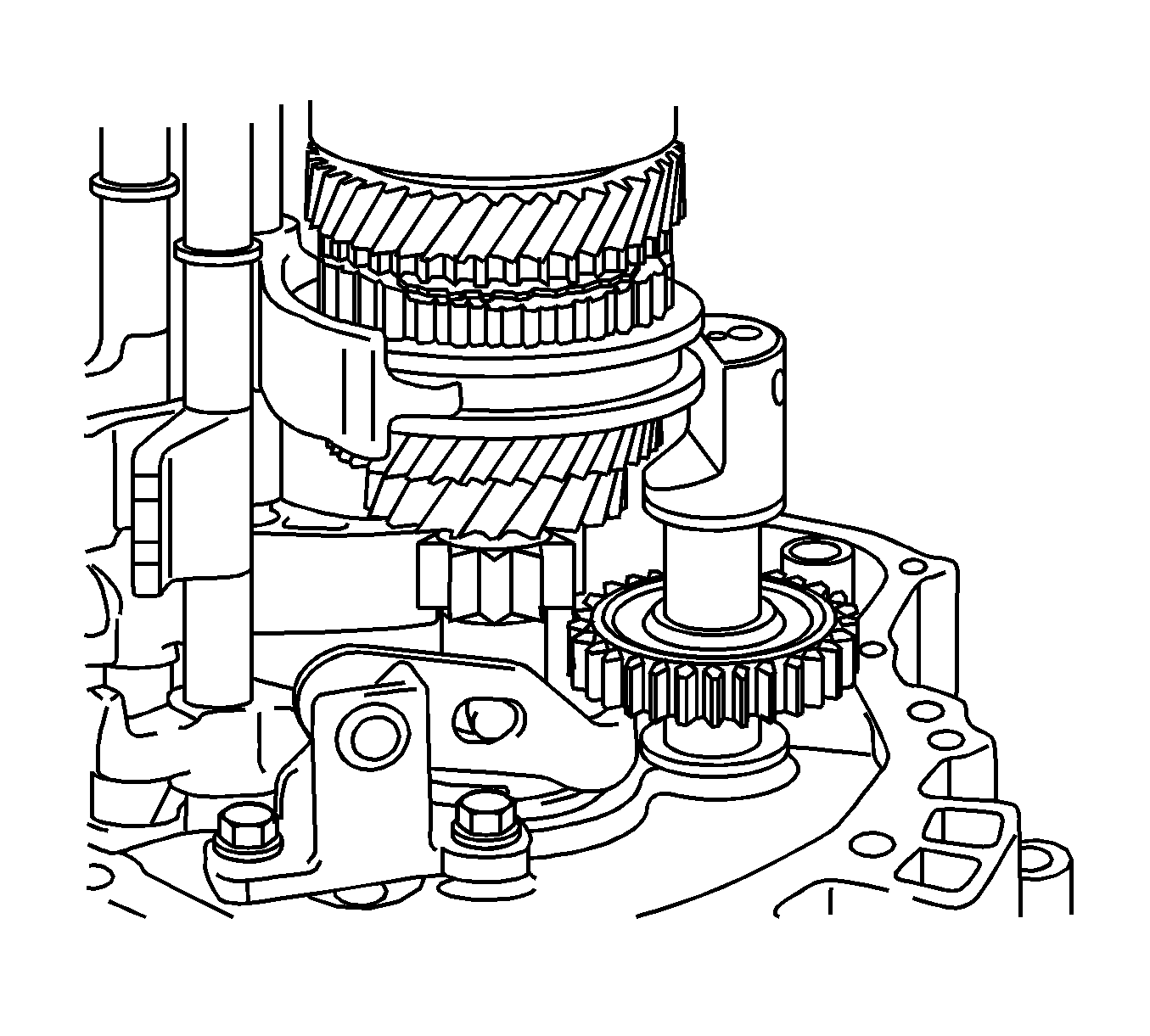
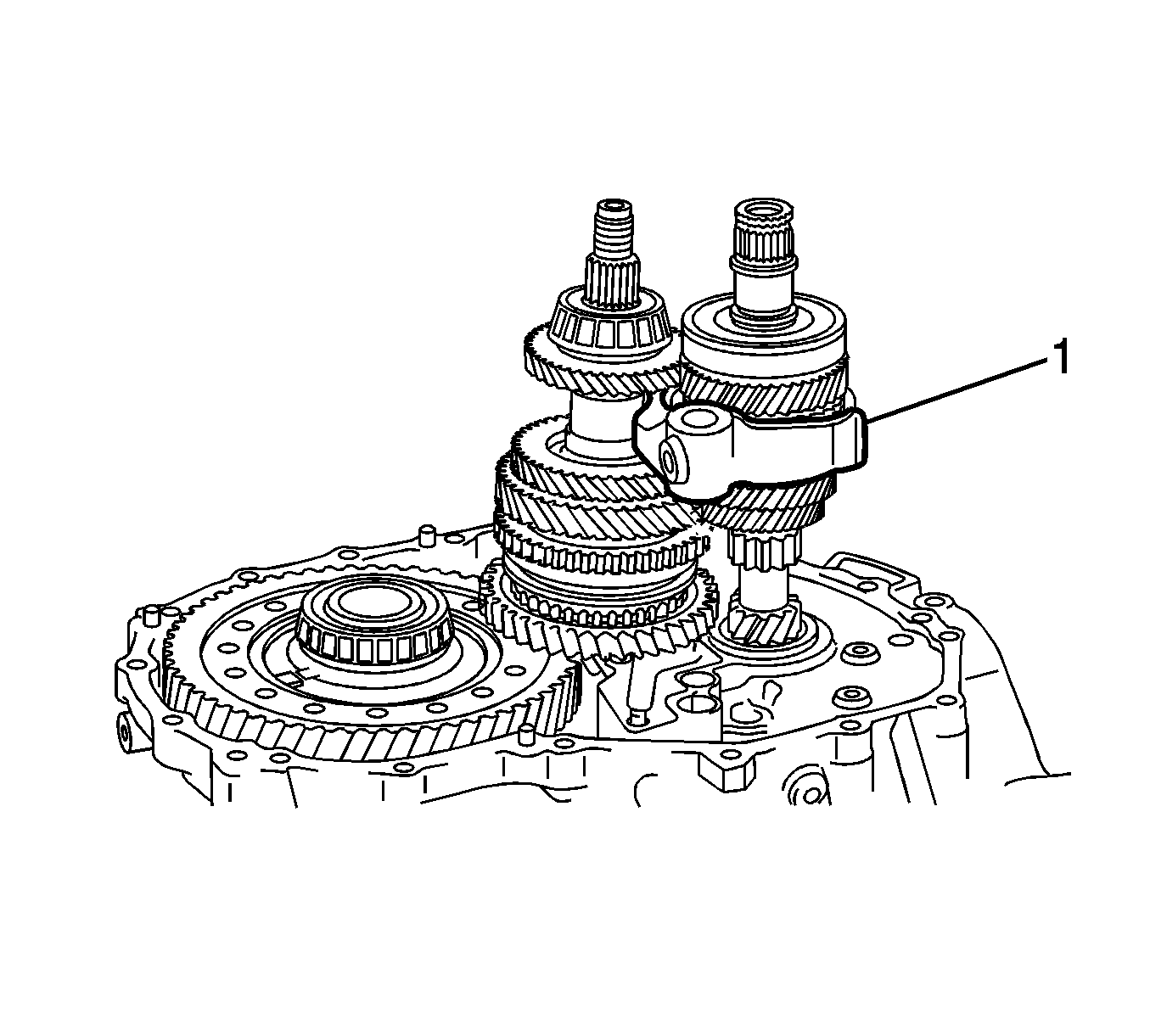
- Remove the No. 2 gear shift fork (1) from the input shaft assembly.
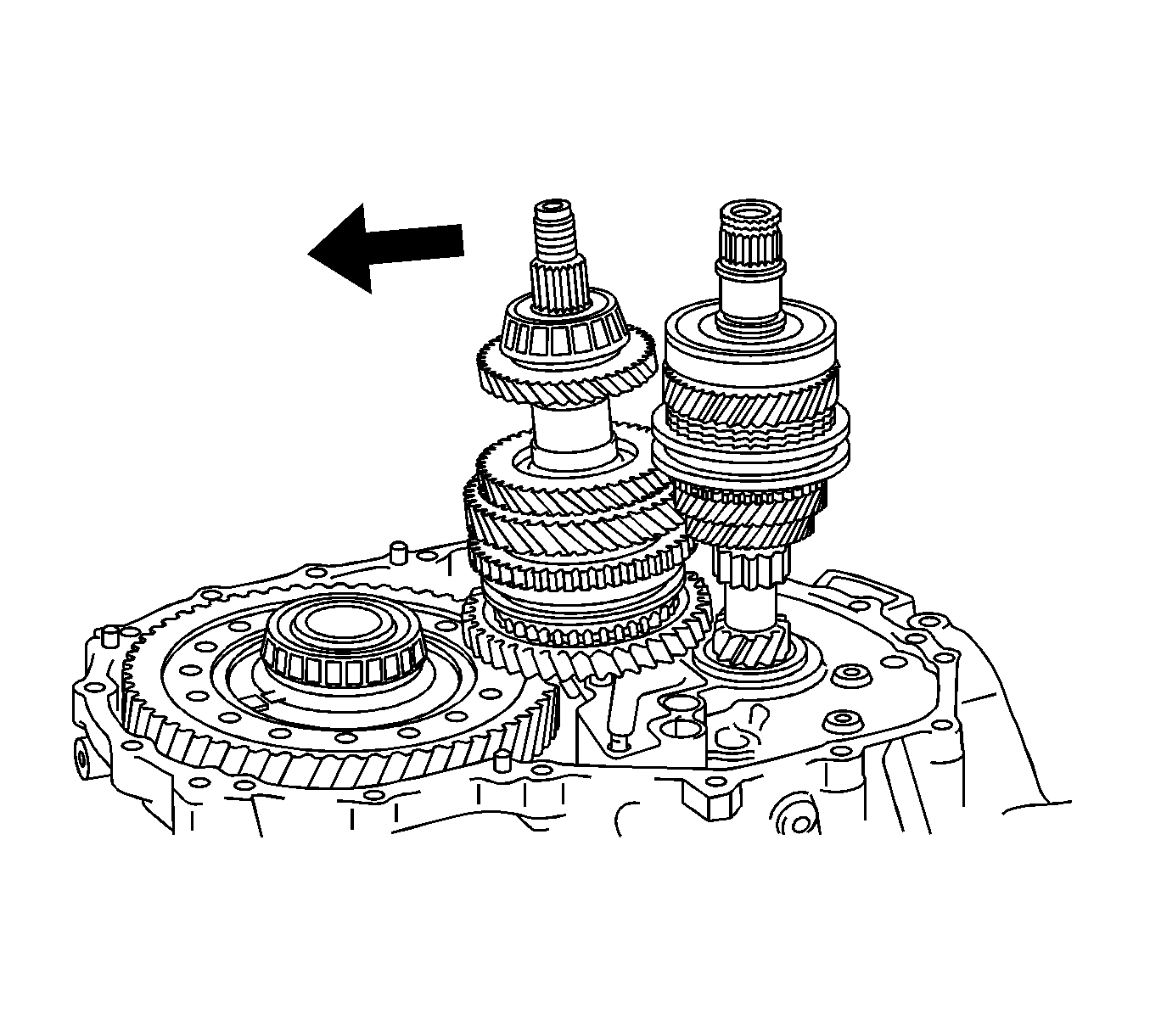
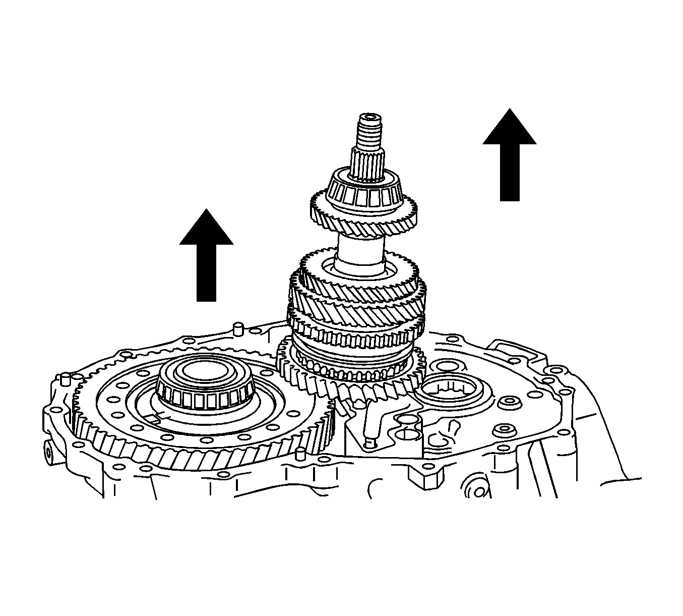
- Tilt the output shaft, and then remove the input shaft from the manual transaxle case.
- Lift the differential case assembly with the output shaft assembly leaned.
- Remove the output shaft assembly from the manual transaxle case.
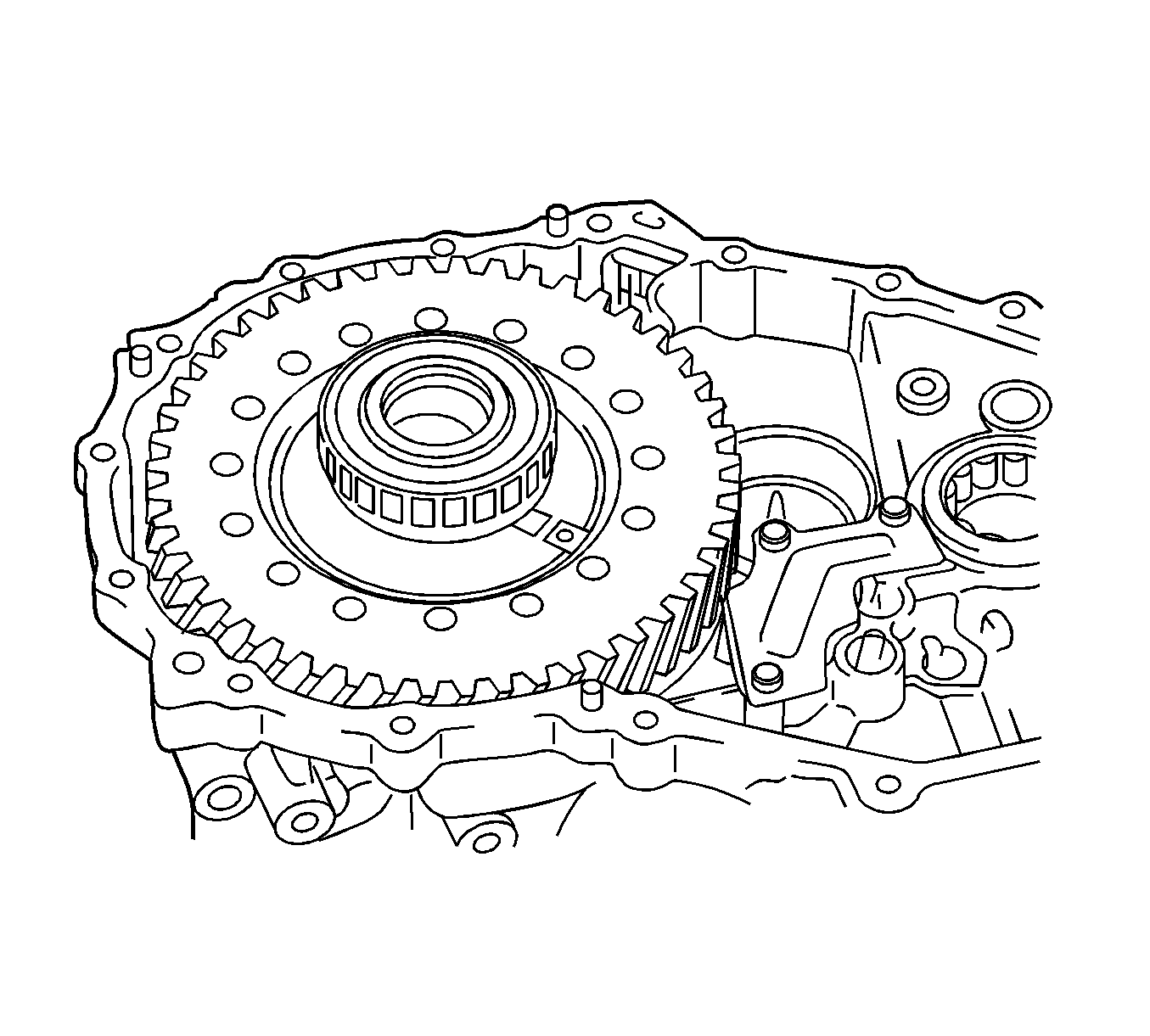
- Remove the differential case assembly from the manual transaxle case.
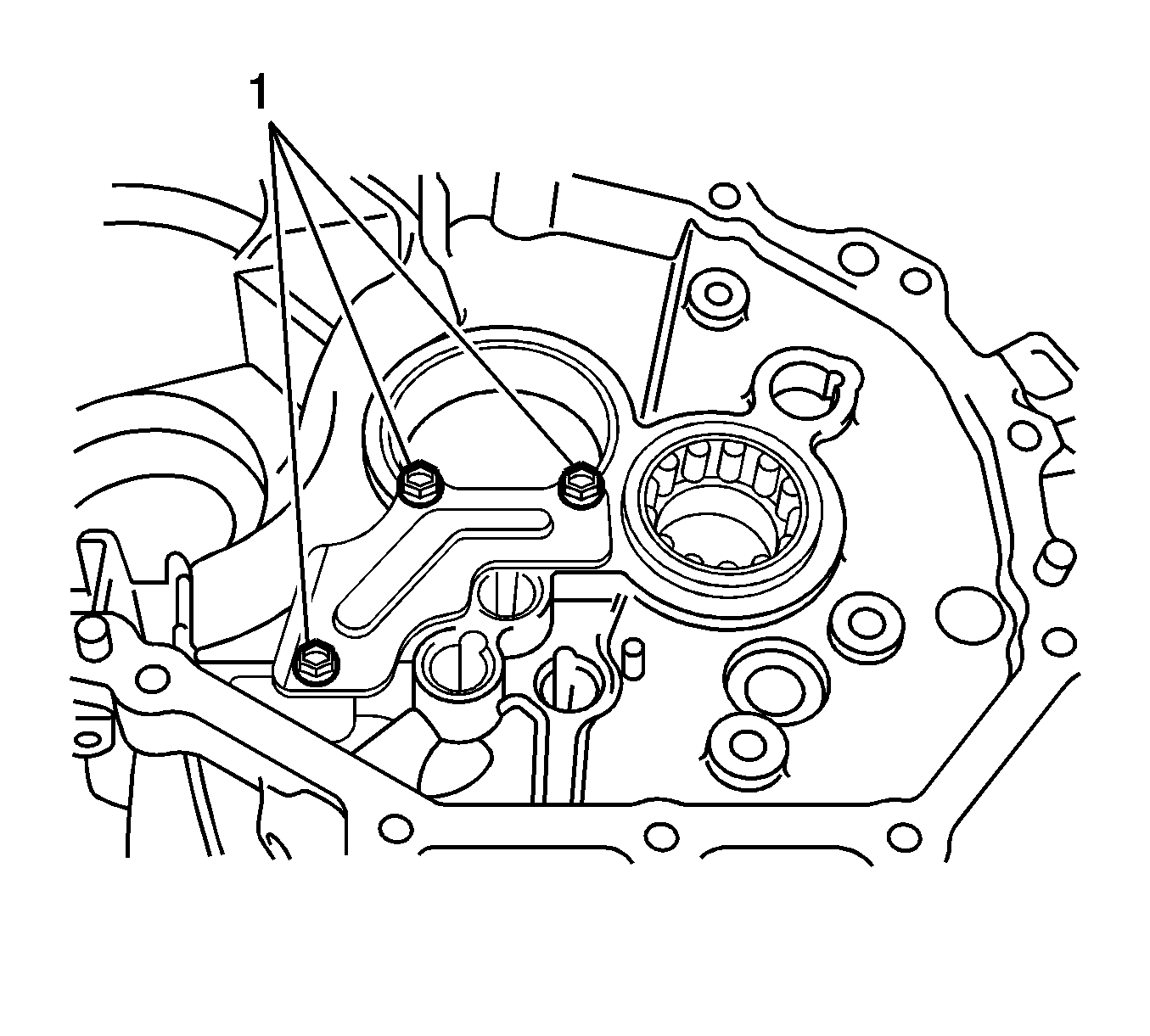
- Remove the bolts (1) and manual transaxle case receiver from the manual transaxle case.
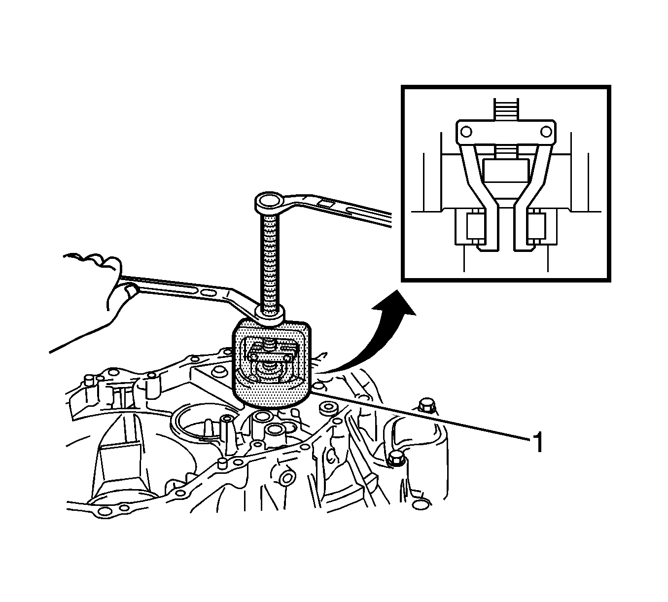
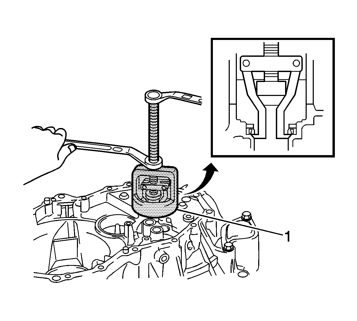
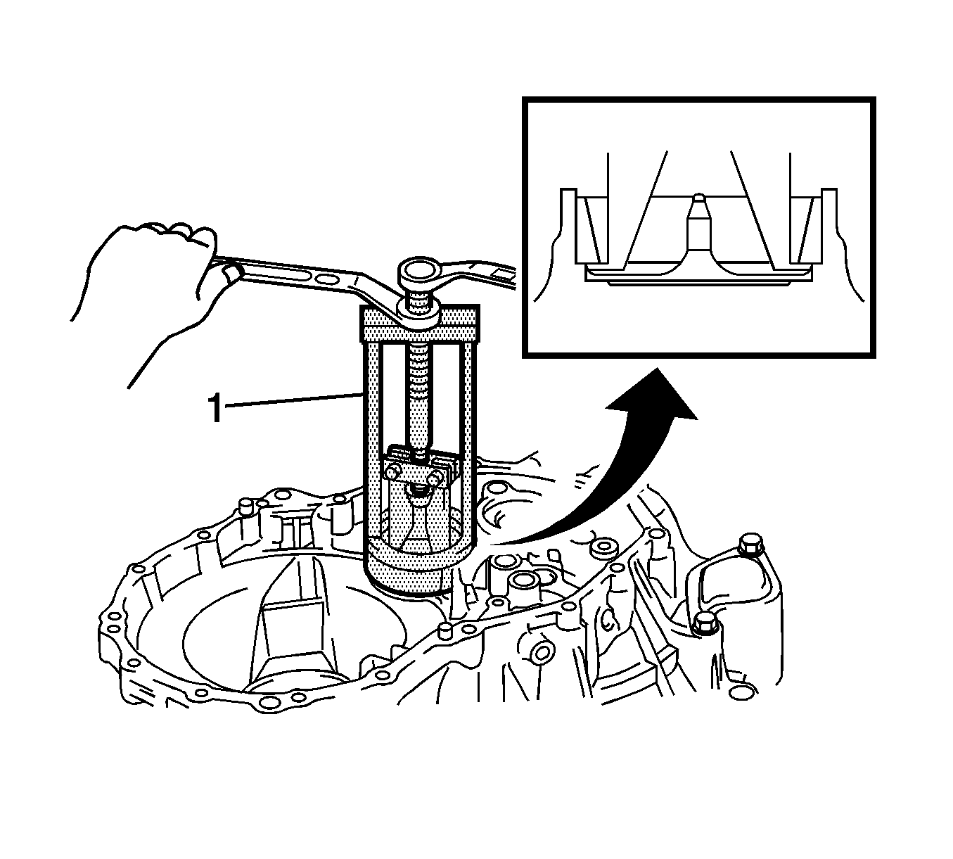
- Using a suitable puller (1), remove the input shaft front bearing (outer race) from the manual transaxle case.
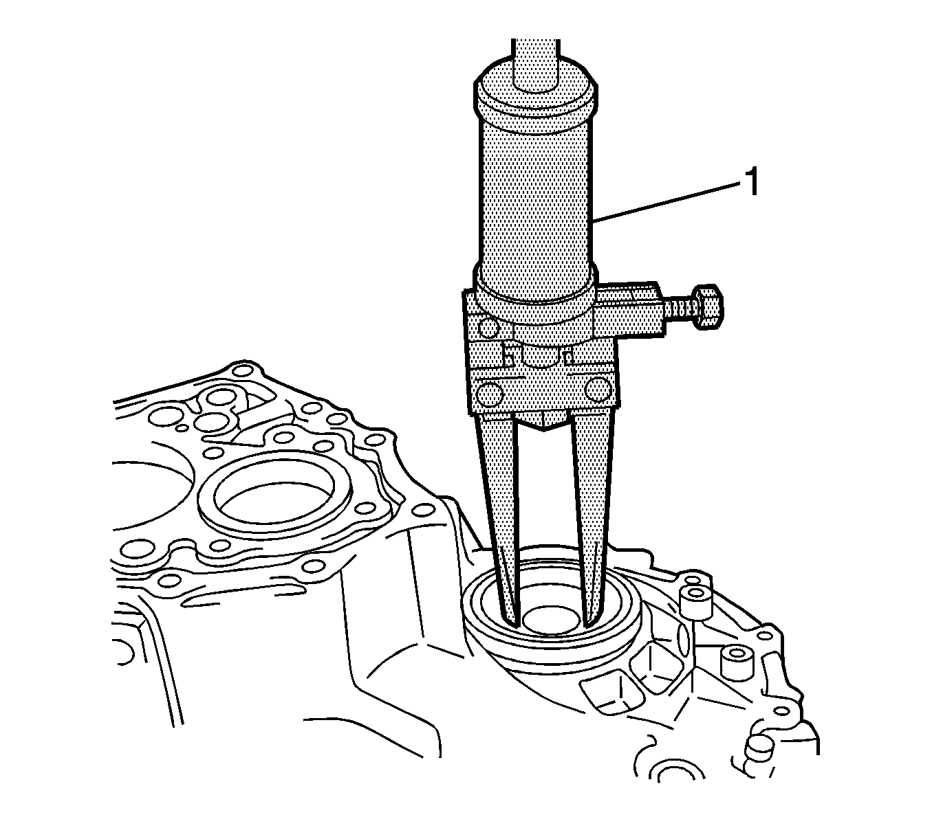
- Using a suitable puller (1), remove the front transaxle case cover oil seal from the manual transaxle case.
- Using a suitable puller (1), remove the output shaft front bearing (outer race) from the manual transaxle case.
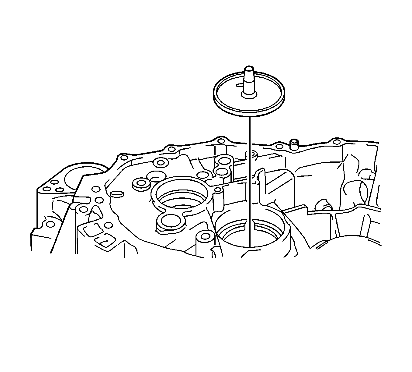
- Remove the output shaft cover from the manual transaxle case.
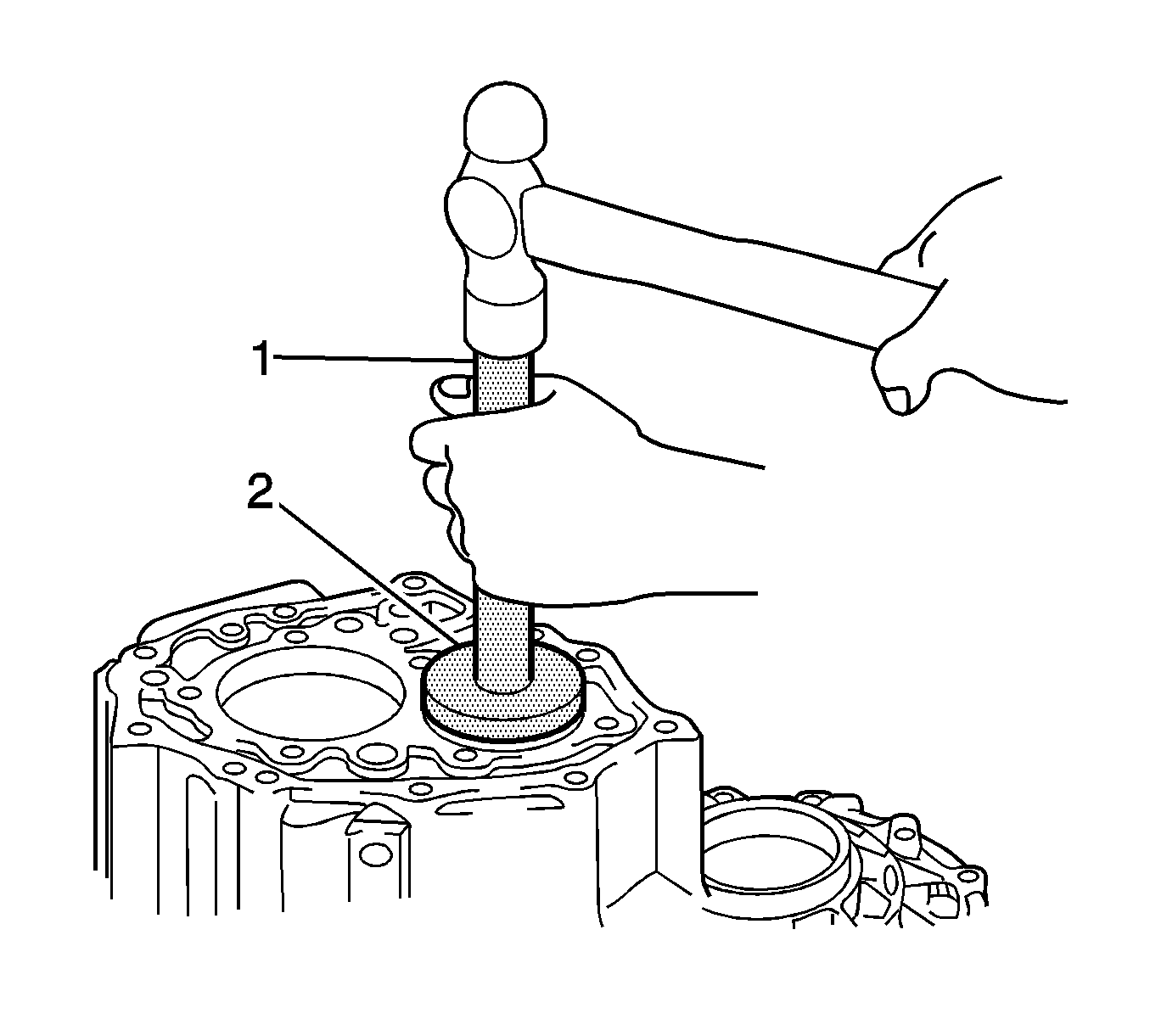
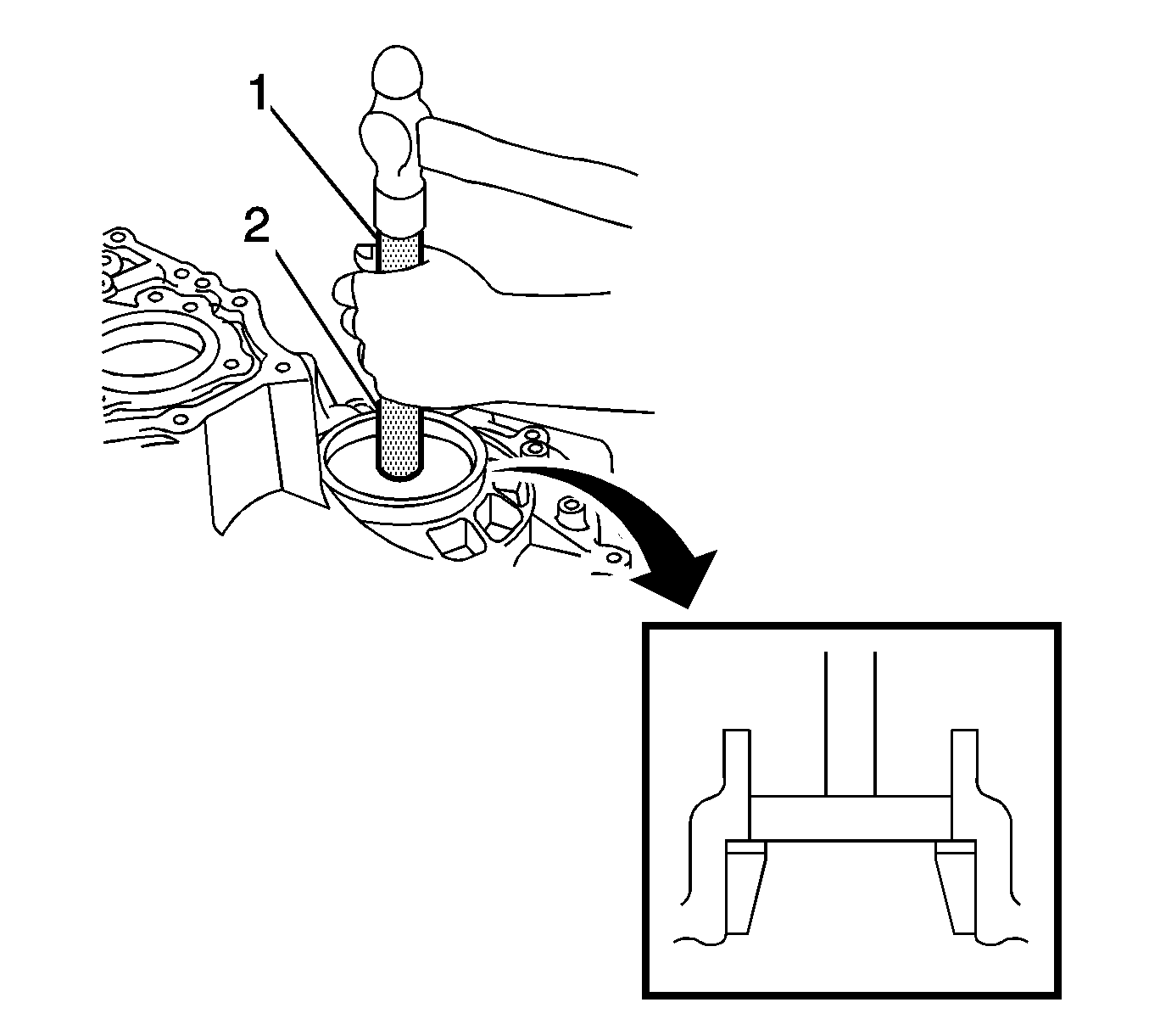
- Using a suitable driver (1) and a hammer, remove the output shaft rear bearing from the manual transmission case (outer race).
- Using a suitable puller (1), remove the transmission case oil seal from the manual transmission case.
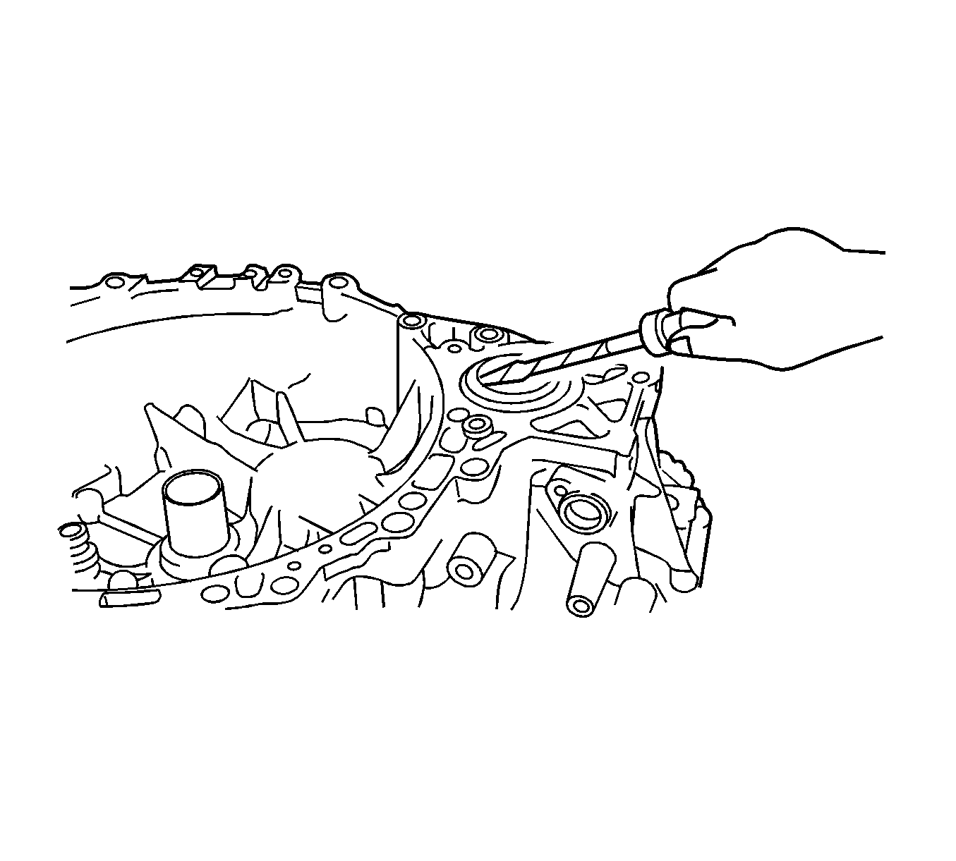
- Using a screwdriver, remove the transaxle case oil seal.
- Using a brass bar and a hammer, remove the front differential case front tapered roller bearing (outer race) from the manual transaxle case.
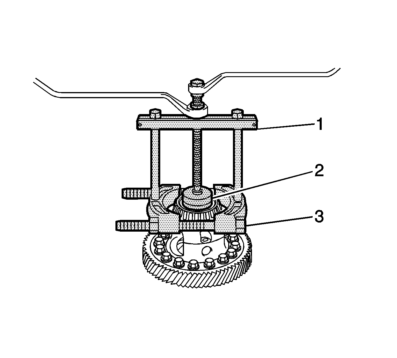
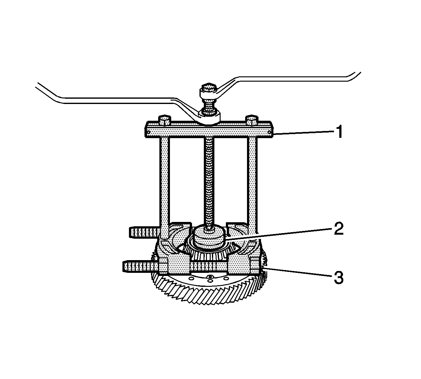
- Using a suitable puller (1), remove the front differential case front tapered roller bearing from the front differential case.
- Using a suitable driver (1) and a hammer, remove the front differential case rear tapered roller bearing (outer race) and front differential case rear shim from the manual transmission case.
- Using a suitable puller (1), remove the front differential case rear tapered roller bearing (inner race) from the front differential case.
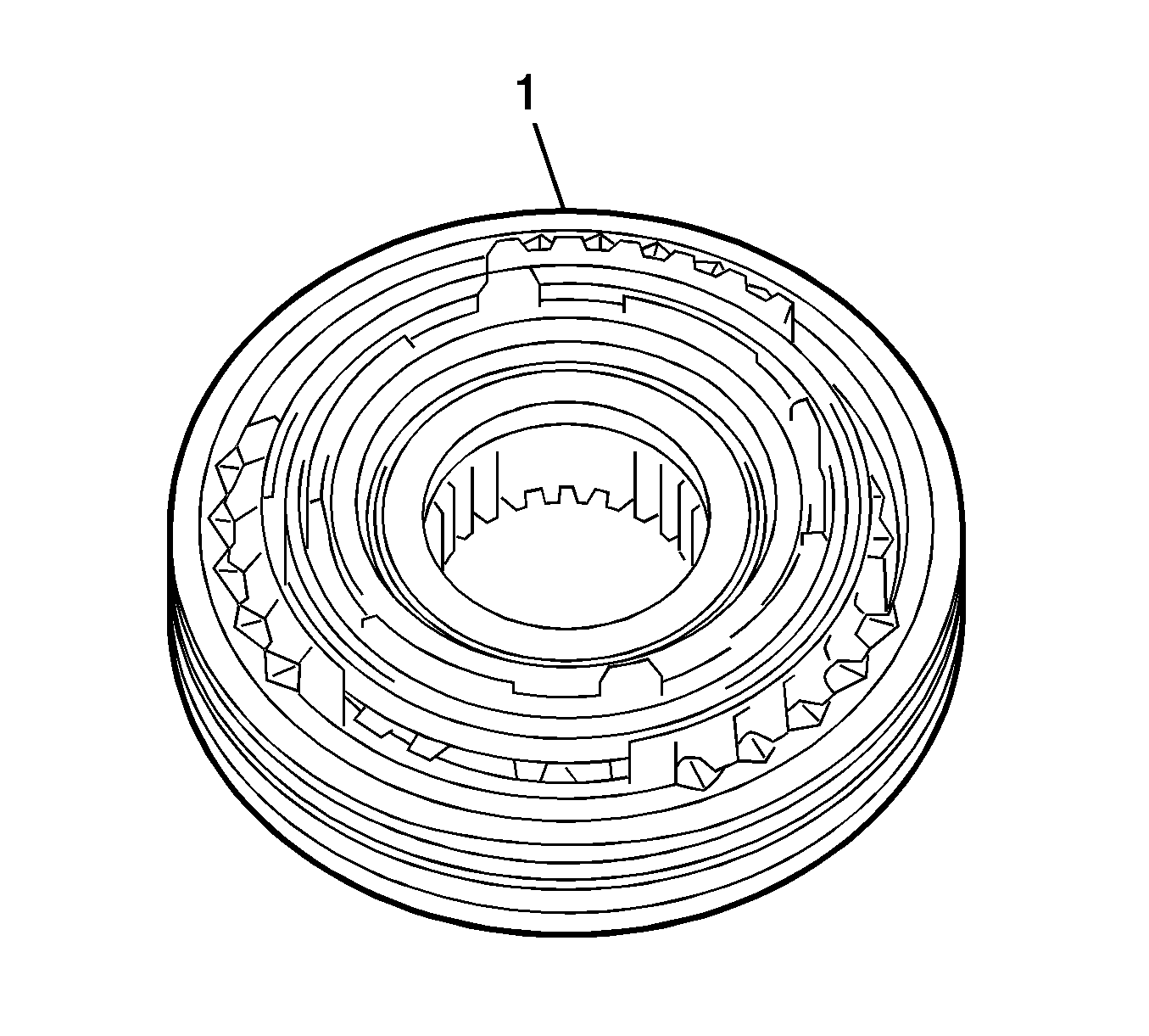
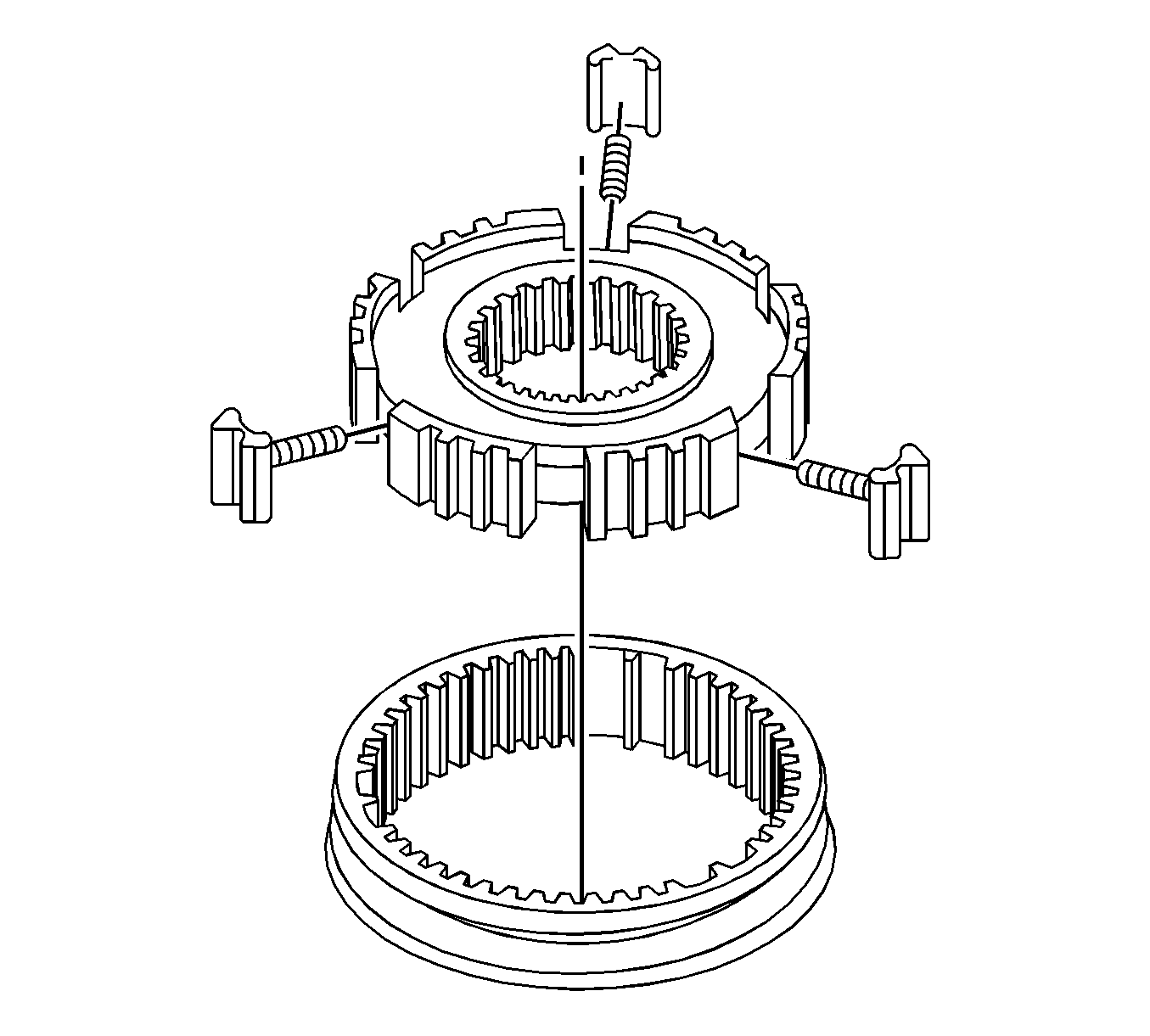
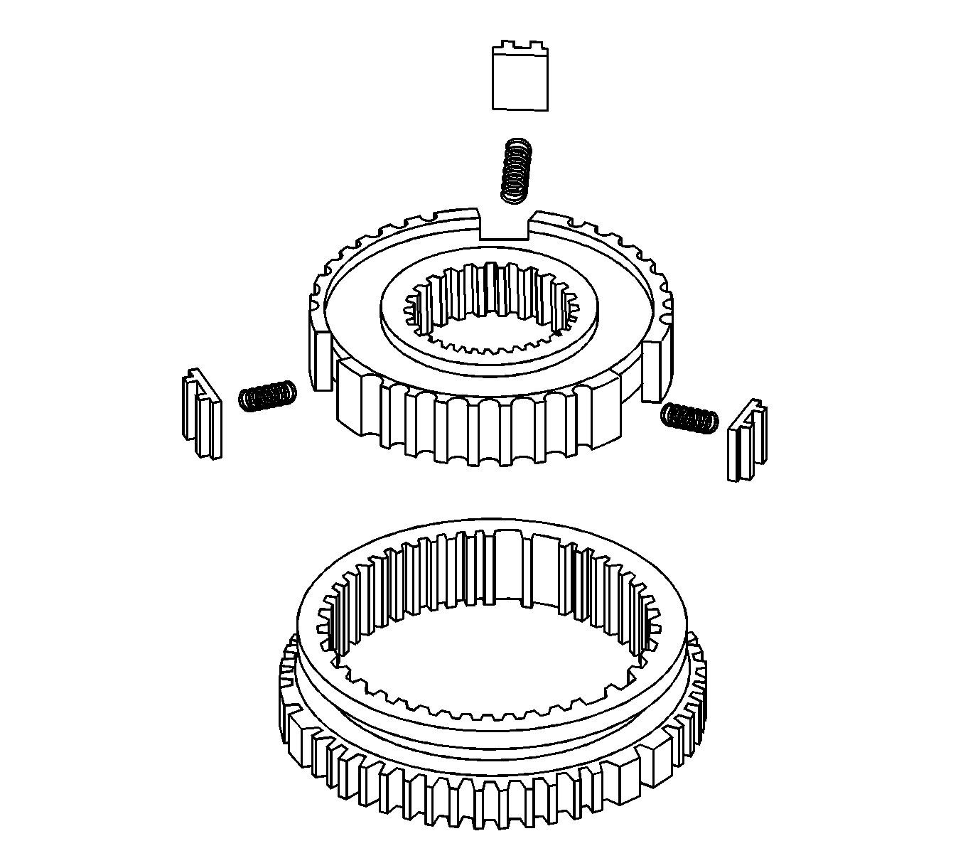
- Remove the No. 3 transmission hub sleeve (1) from the No. 3 transmission clutch hub.
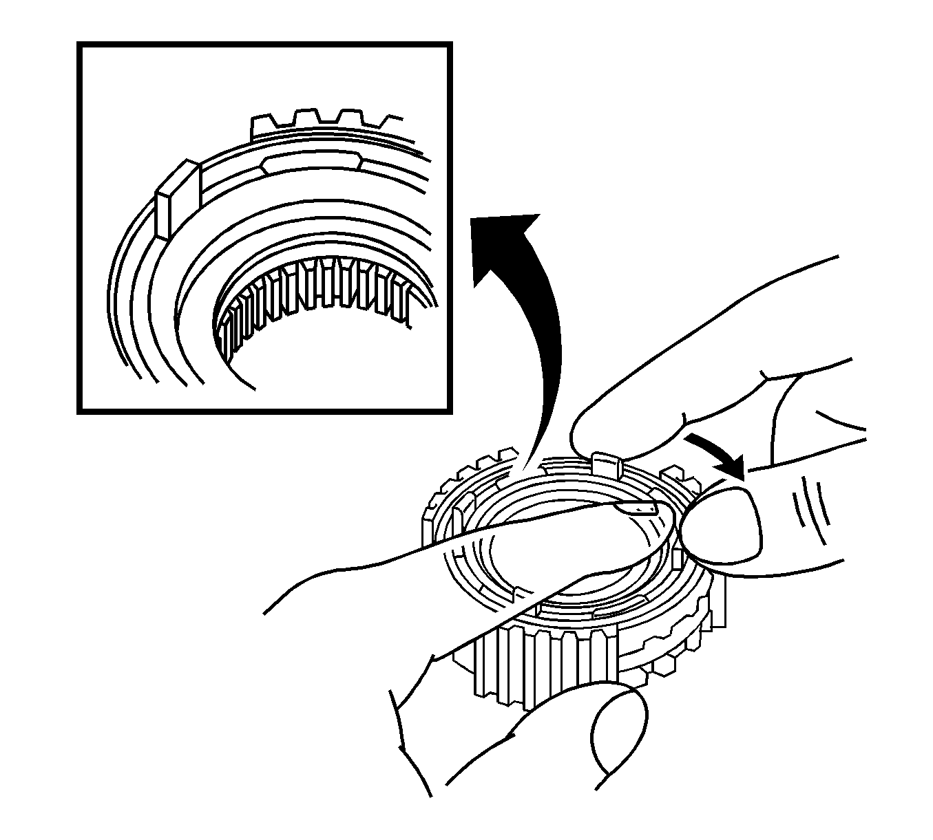
- Remove the No. 3 synchromesh shifting key springs (1) from the No. 3 transmission clutch hub while pushing on the No. 3 synchromesh shifting key spring.
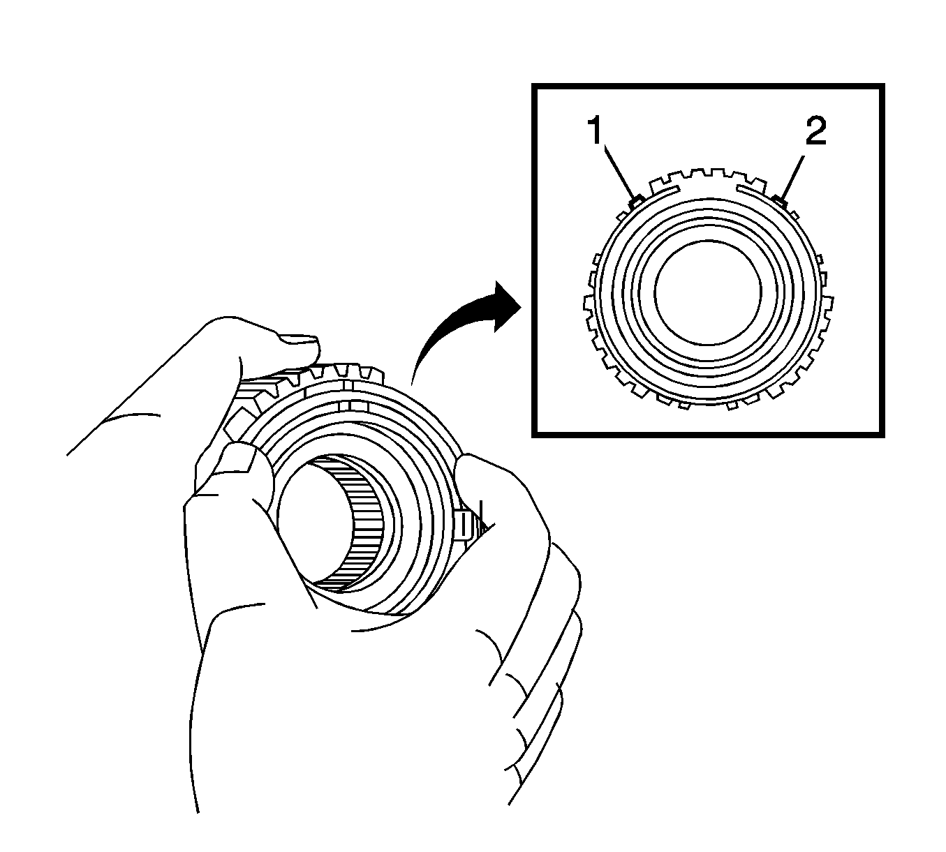
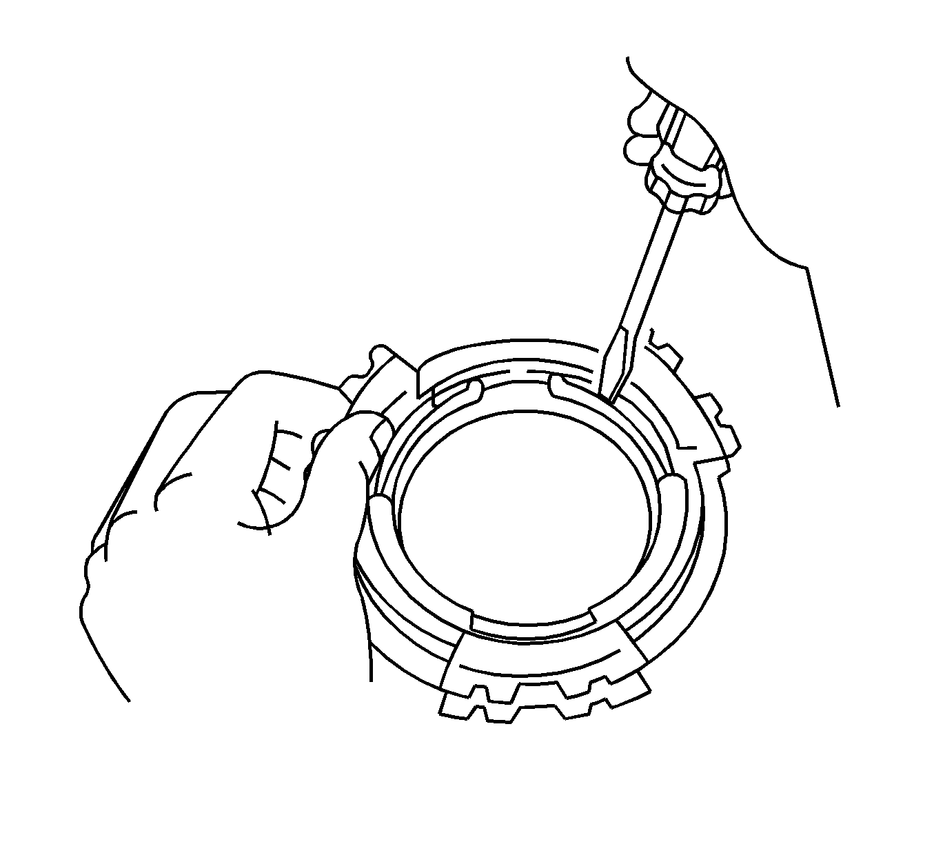
- Using a screwdriver, remove the synchronizer pull ring snap ring.
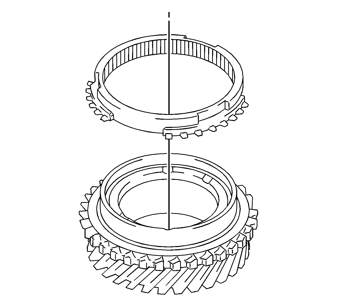
- Remove the synchronizer pull ring, No. 5 synchronizer ring outer, No. 5 synchronizer ring inner, and No. 5 synchronizer ring middle from the No. 5 synchronizer ring inner.
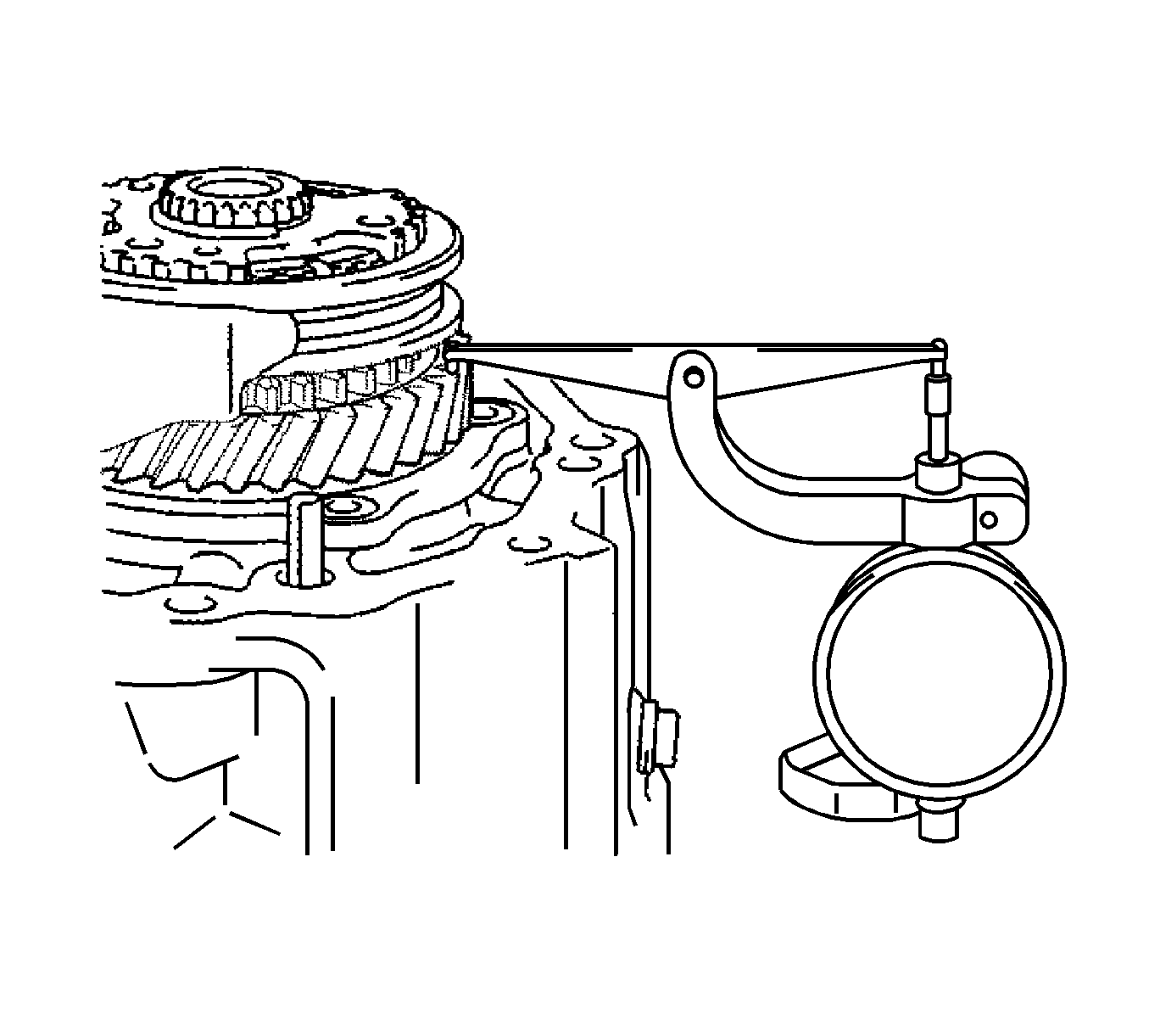
- Using a dial indicator, inspect the 5th gear thrust clearance.
- If clearance is not as specified, replace the No. 3 transmission clutch hub, 5th gear, or input shaft rear radial ball bearing.
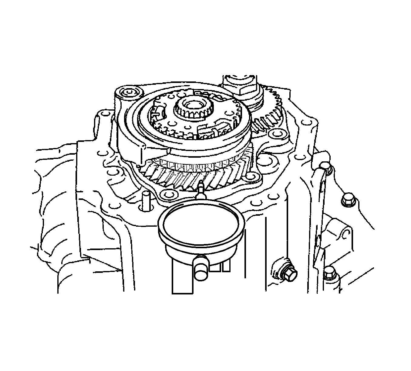
- Using a dial indicator, inspect the 5th gear radial clearance.
- If clearance is not as specified, replace the 5th gear, 5th gear needle roller bearing, or input shaft.
- Using a caliper gage, measure the inside diameter of the reverse idler gear.
- If the inside diameter exceeds the maximum, replace the reverse idler gear.
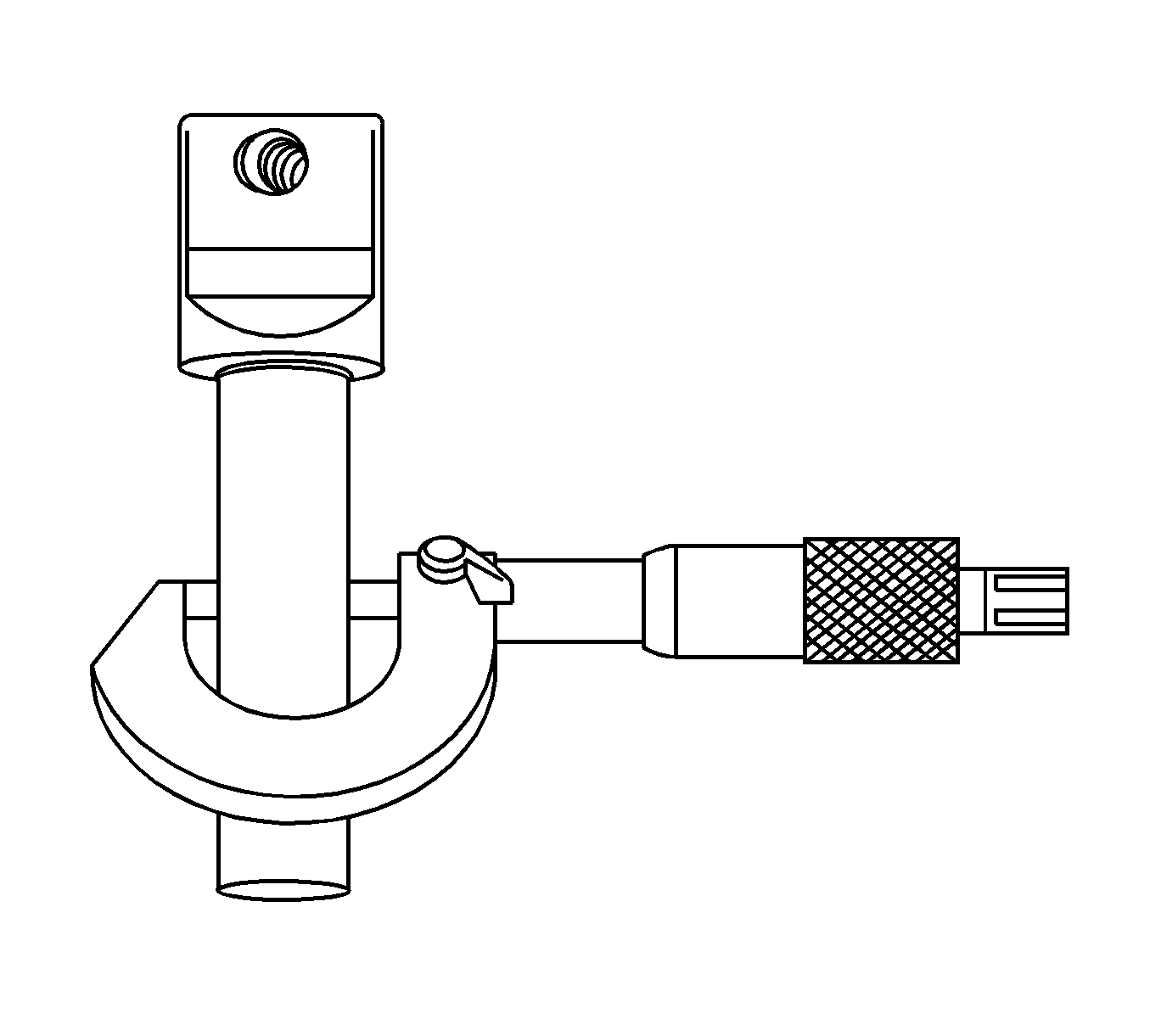
- Using a micrometer, measure the outside diameter of the reverse idler gear shaft.
- If the outside diameter is less than the minimum, replace the reverse idler gear shaft.
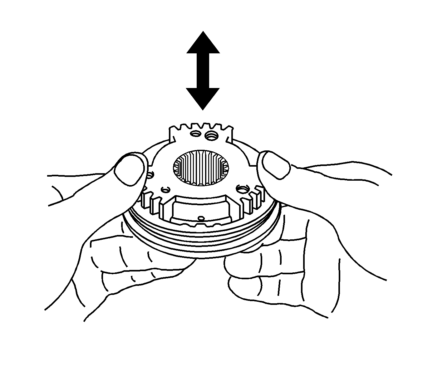
- Inspect the sliding condition between the No. 3 transmission clutch hub and the No. 3 transmission hub sleeve.
- Inspect the tip of the spline gear on the No. 3 transmission hub sleeve for wear.
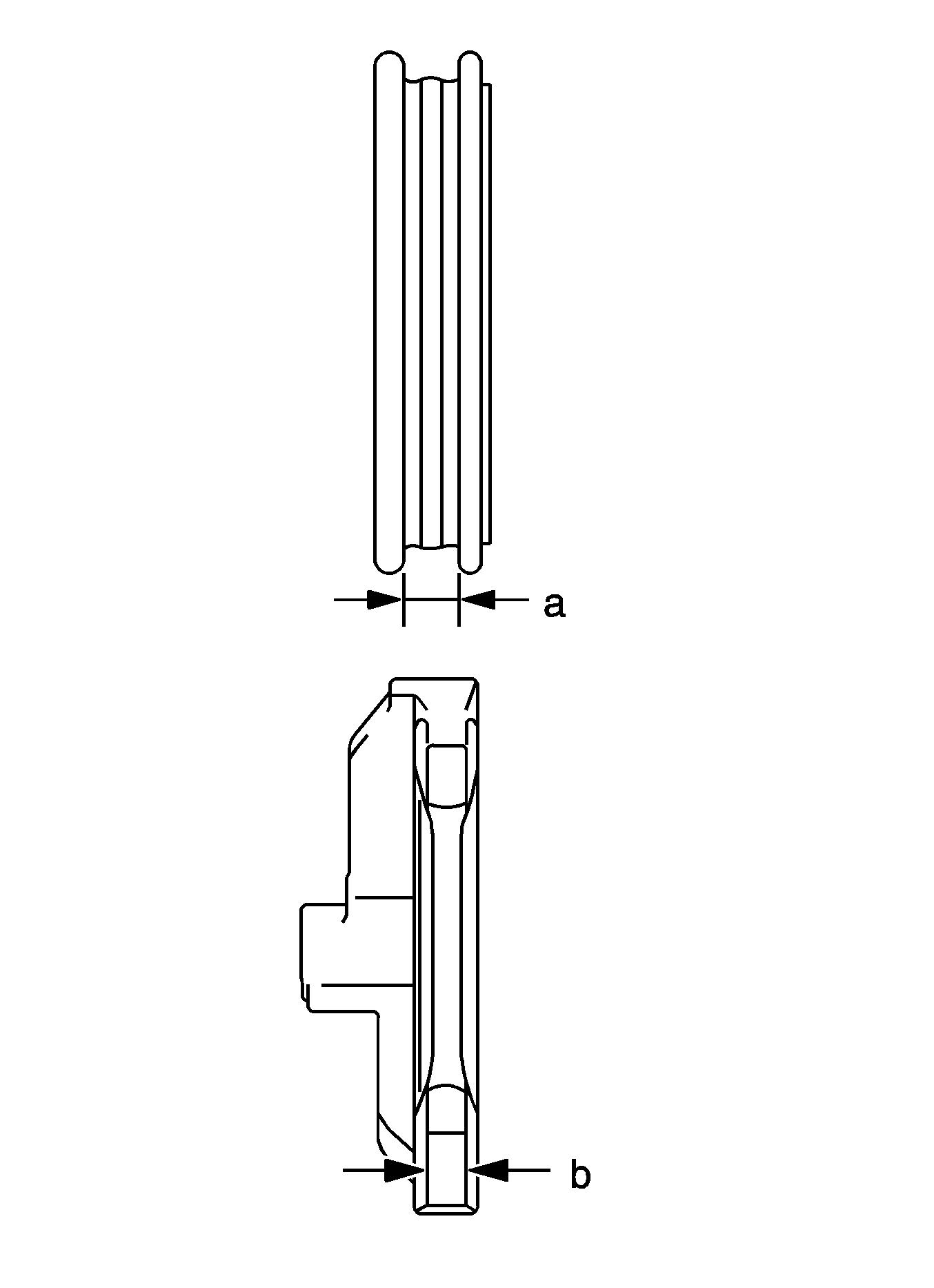
- Using vernier calipers, measure the width of the No. 3 transmission hub sleeve groove and the thickness of the claw on the No. 3 gear shift fork, and calculate the clearance.
- If clearance is not as specified, replace the No. 3 transmission hub sleeve and No. 3 gear shift fork with new ones.
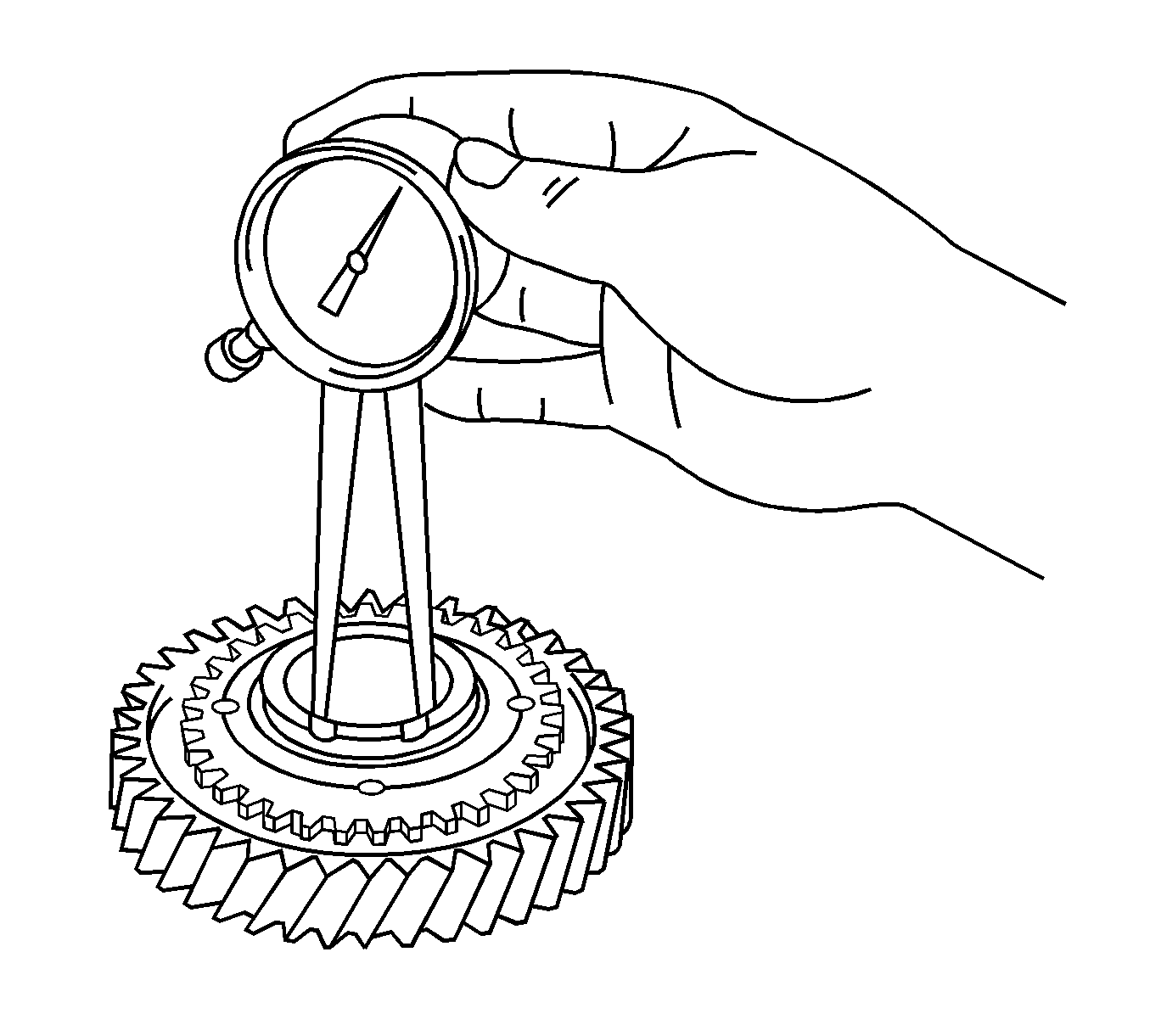
- Using a caliper gage, measure the inside diameter of the 5th gear.
- If the inside diameter exceeds the maximum, replace the 5th gear.
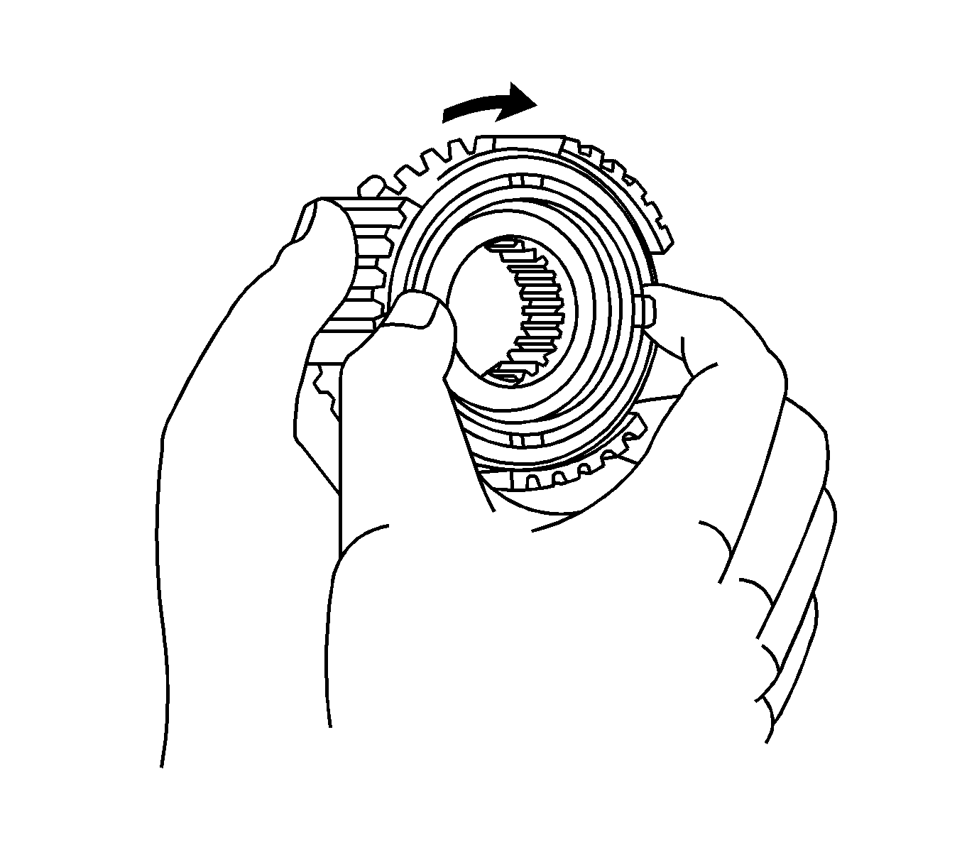
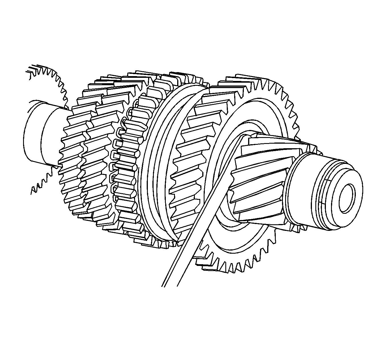
- Check that the No. 5 synchronizer ring rotates smoothly.
- Check that the No. 5 synchronizer ring does not rotate while pushing it against the No. 3 clutch hub.
- Hold the input shaft assembly in a vise using aluminum plates.
- Using 2 screwdrivers and a hammer, remove the input shaft rear bearing shaft snap ring from the input shaft.
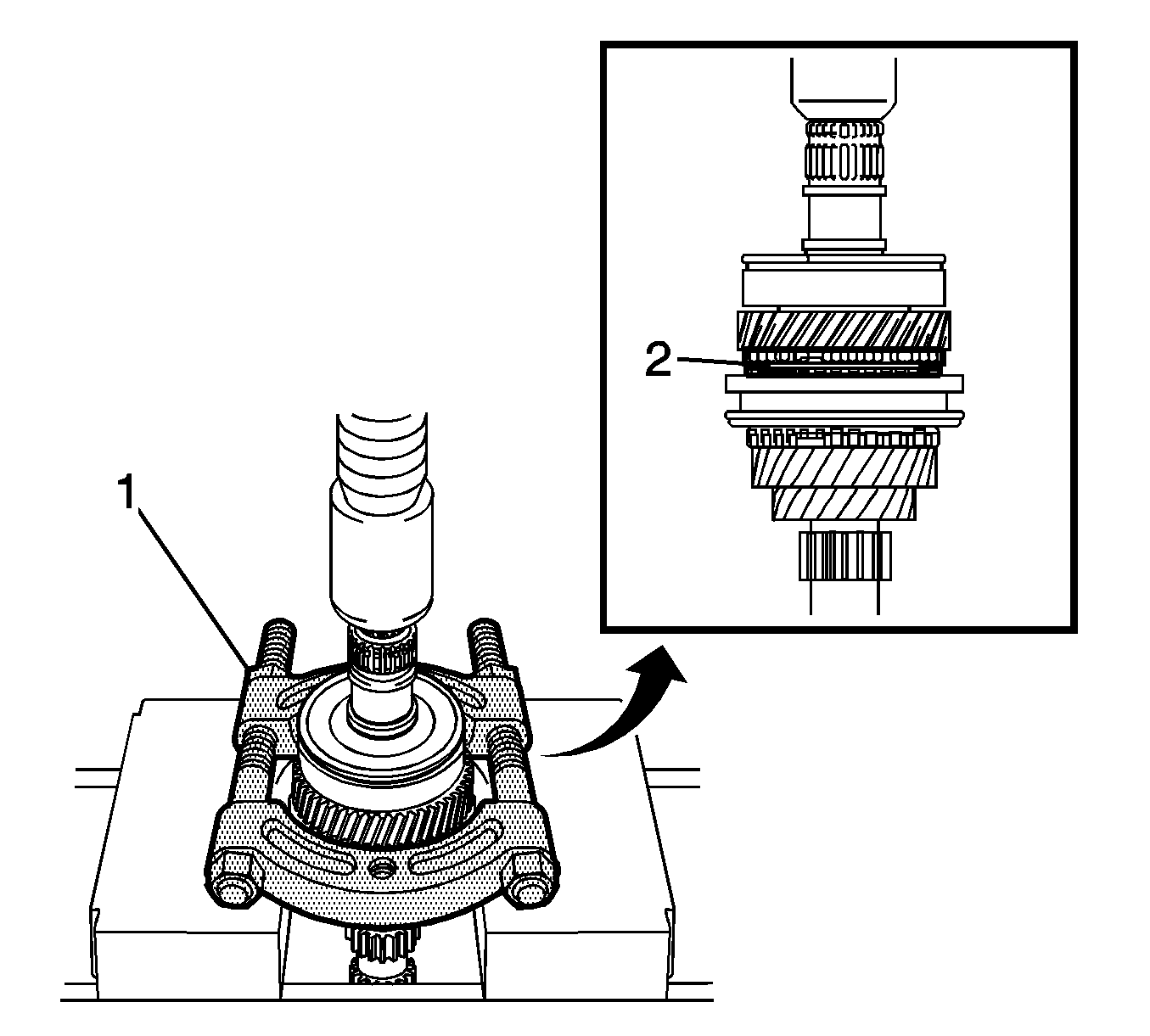
- Using a press (1), remove the input shaft rear bearing and 4th gear.
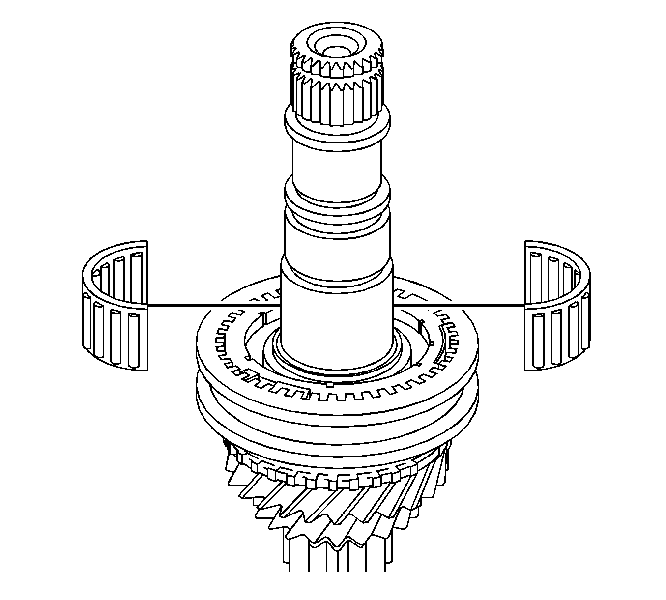
- Remove the 4th gear needle roller bearing from the input shaft.
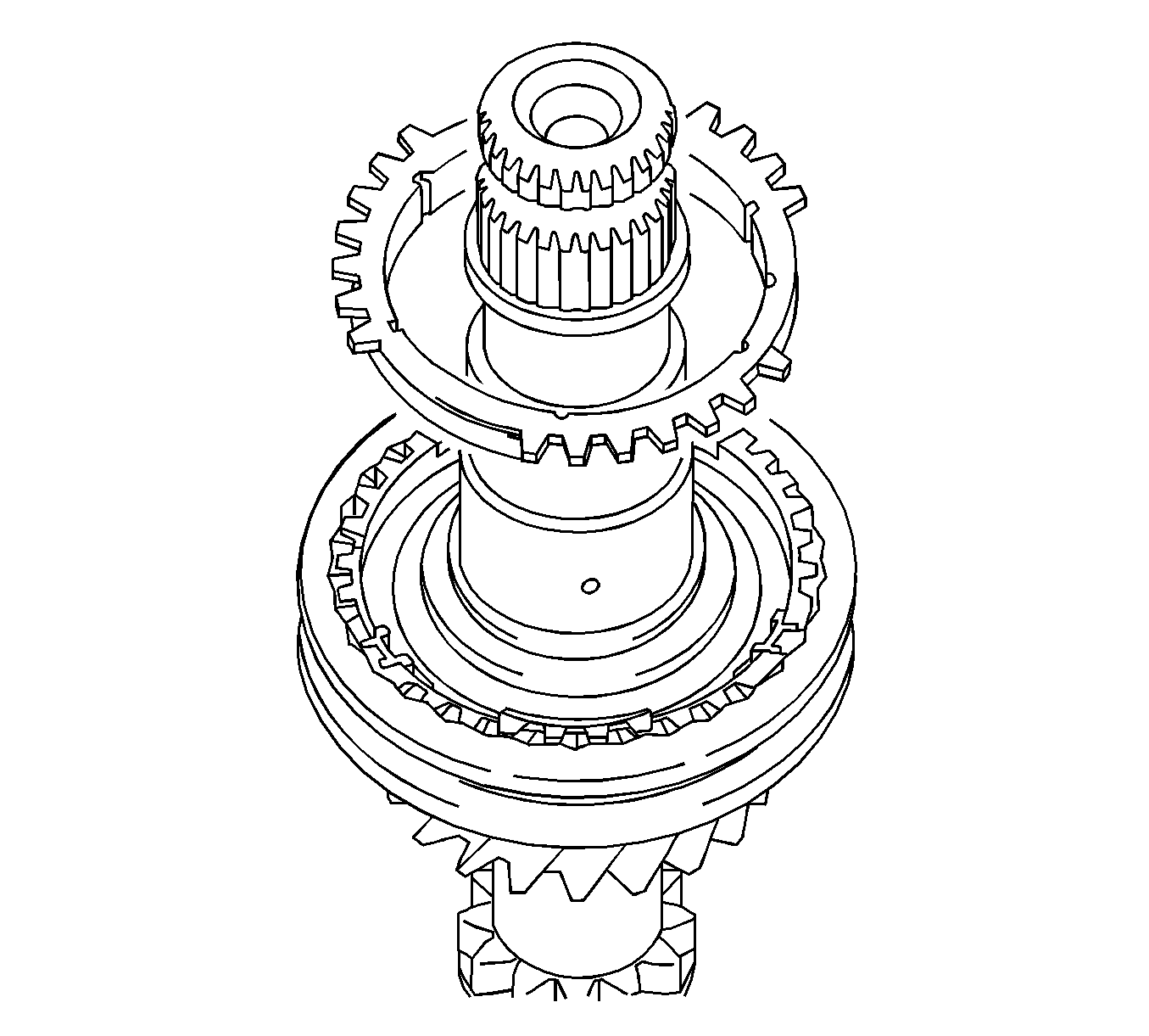
- Remove the No. 4 synchronizer ring from the No. 2 transmission clutch hub.
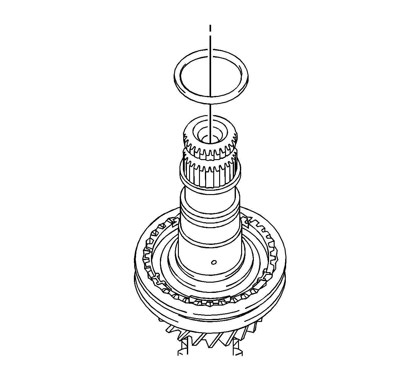
- Remove the 4th gear bearing spacer from the No. 2 transmission clutch hub.
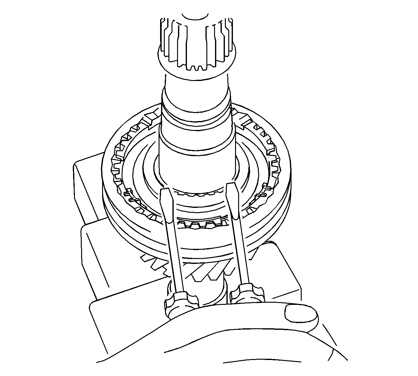
- Using 2 screwdrivers and a hammer, remove the No. 2 clutch hub setting shaft snap ring from the input shaft.
- Using a press (1), remove the No. 2 transmission clutch hub and 3rd gear from the input shaft.
- Remove the 3rd gear needle roller bearing from the input shaft.
- Remove the No. 3 synchronizer ring from the 3rd gear.
- Remove the No. 2 transmission hub sleeve, No. 2 synchromesh shifting keys, and No. 2 synchromesh shifting key springs from the No. 2 transmission clutch hub.
- Using a press (1), remove the input shaft front bearing (inner race) from the input shaft.
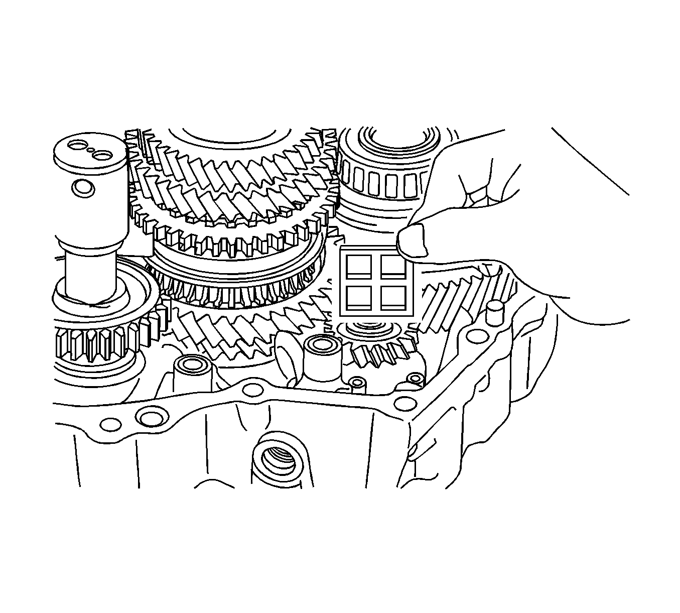
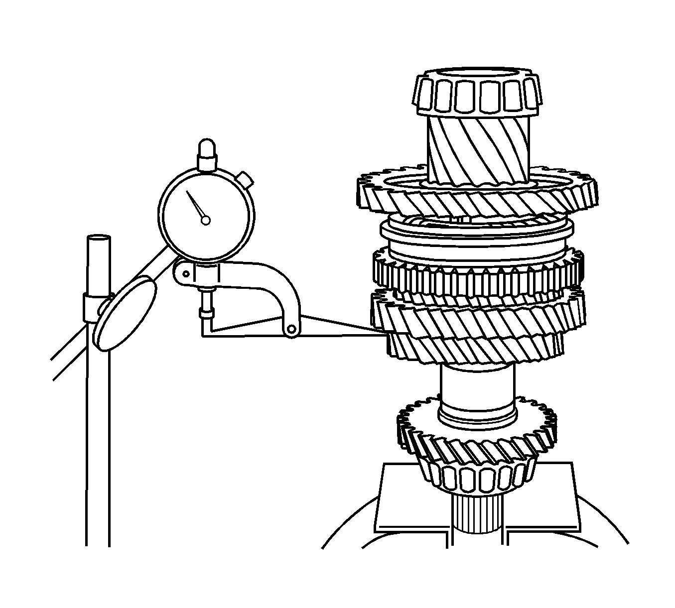
- Using a feeler gage, measure the 4th gear thrust clearance.
- If the clearance is out of specification, replace the No. 2 transmission clutch hub, 4th gear, or input shaft rear radial ball bearing.
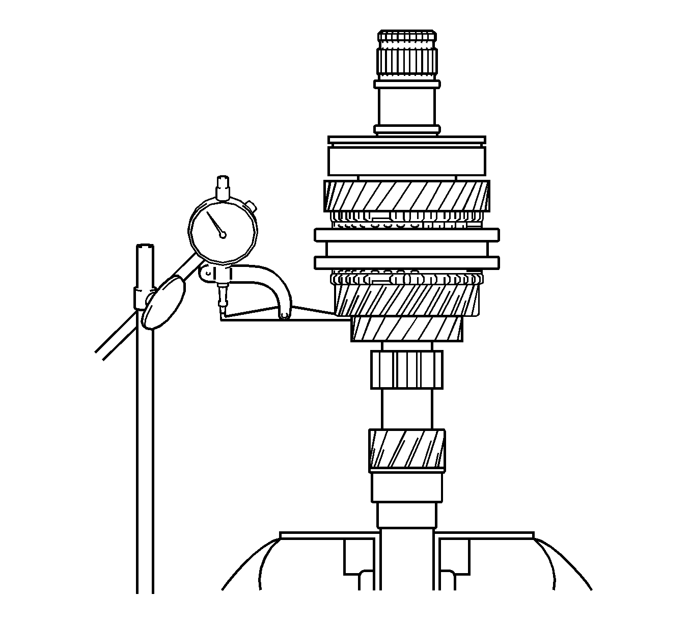
- Using a dial indicator, measure the 3rd gear thrust clearance.
- If the clearance is out of specification, replace the No. 2 transmission clutch hub, 3rd gear, or input shaft.
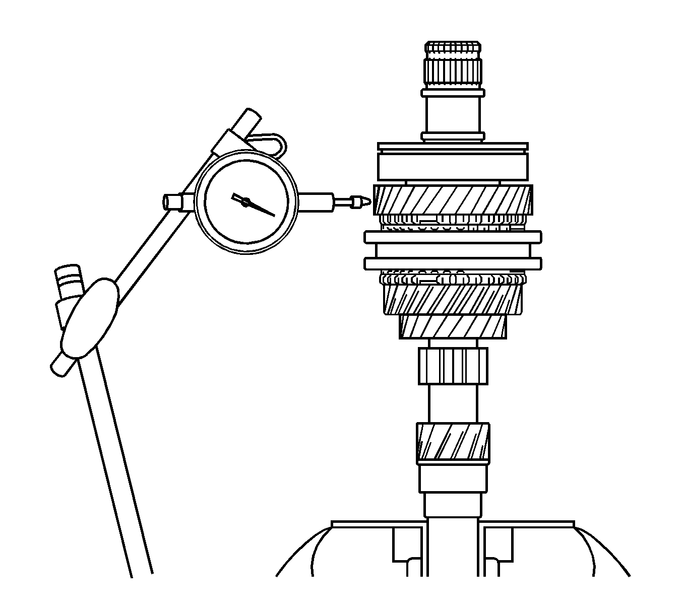
- Using a dial indicator, measure the 4th gear radial clearance.
- If clearance is out of specification, replace the 4th gear, needle roller bearing, or input shaft.
- Using a dial indicator, measure the 3rd gear radial clearance.
- If clearance is out of specification, replace the 3rd gear, needle roller bearing, or input shaft.
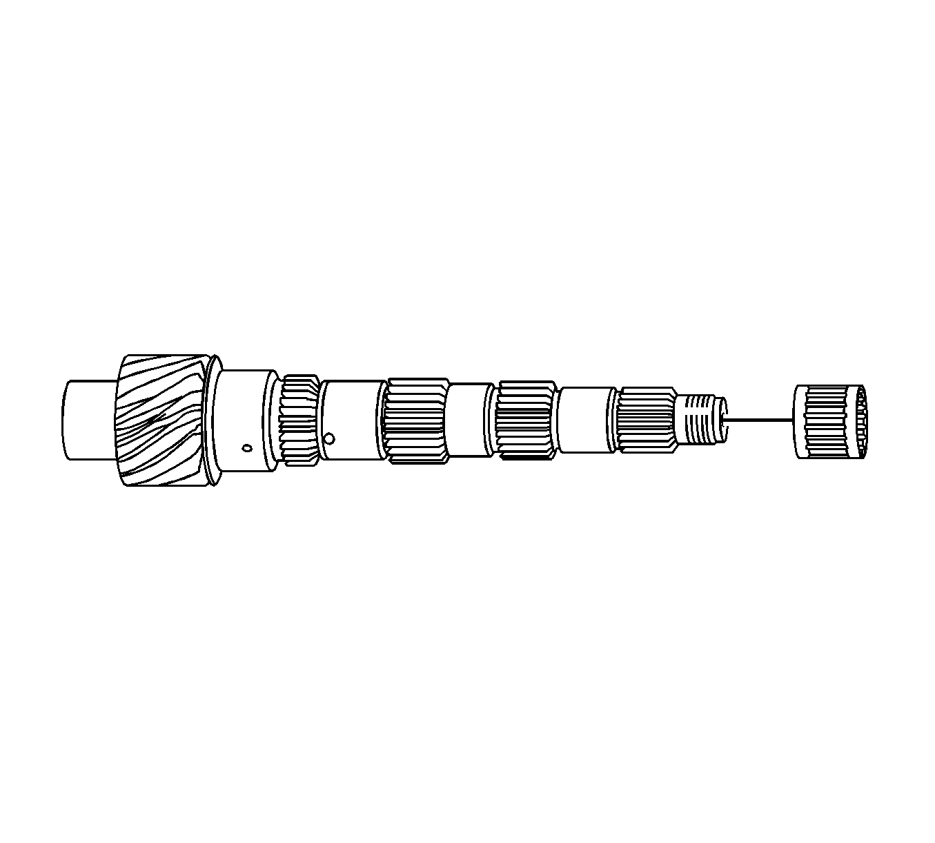
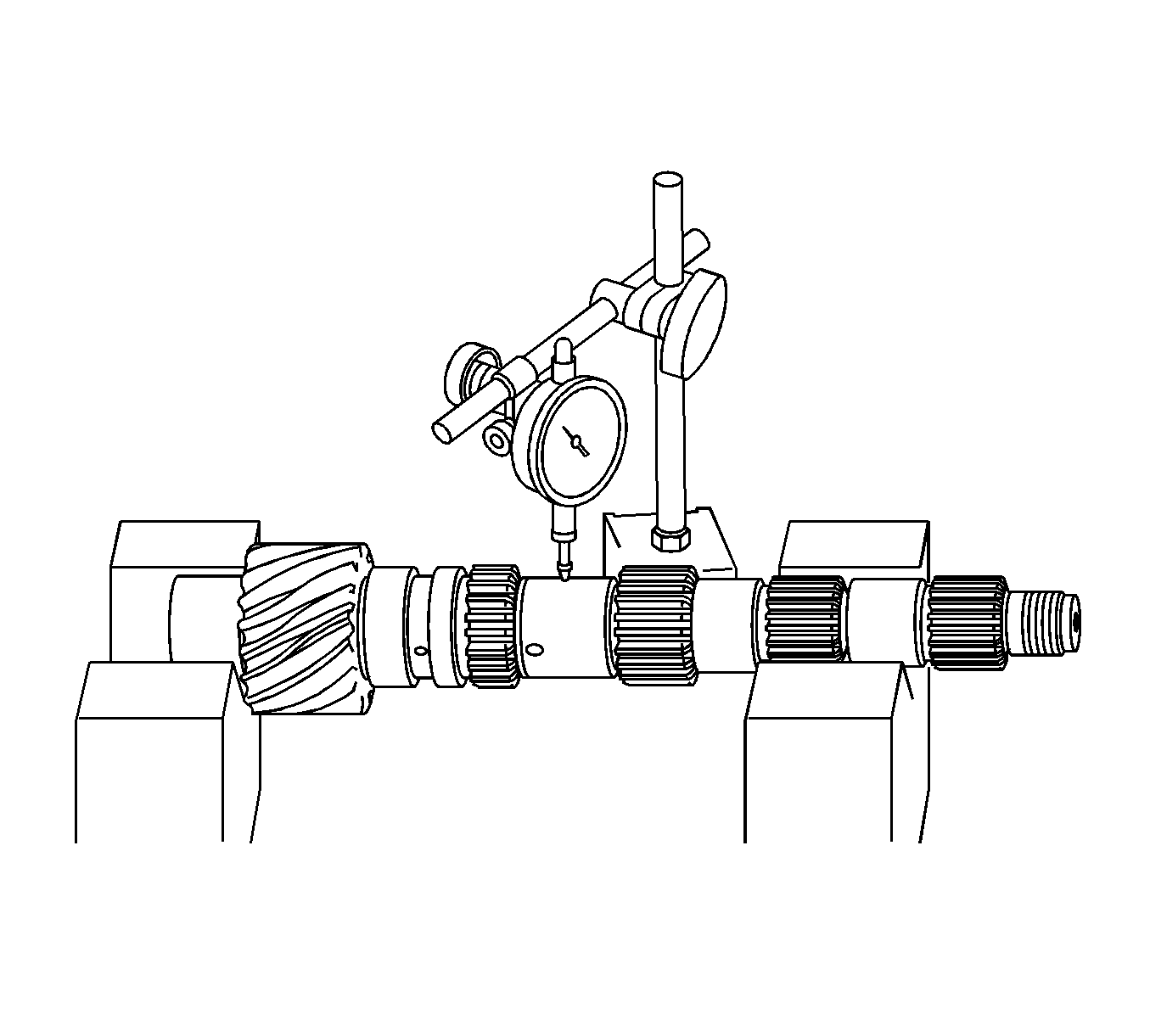
- Using V-blocks and a dial indicator, inspect the shaft for runout.
- If the runout exceeds the maximum, replace the input shaft.
- Using a cylinder gage, measure the inside diameter of the 4th gear.
- If the inside diameter exceeds the maximum, replace the 4th gear.
- Using a cylinder gage, measure the inside diameter of the 3rd gear.
- If the inside diameter exceeds the maximum, replace the 3rd gear.
- Coat the 4th gear cone with gear oil. Turn the No. 4 synchronizer ring in one direction while pushing it against the 4th gear cone. Check that the ring locks. If the No. 4 synchronizer ring does not lock, replace the ring or the 4th gear.
- Using a feeler gage, measure the clearance between the No. 4 synchronizer ring back and 4th gear spline end.
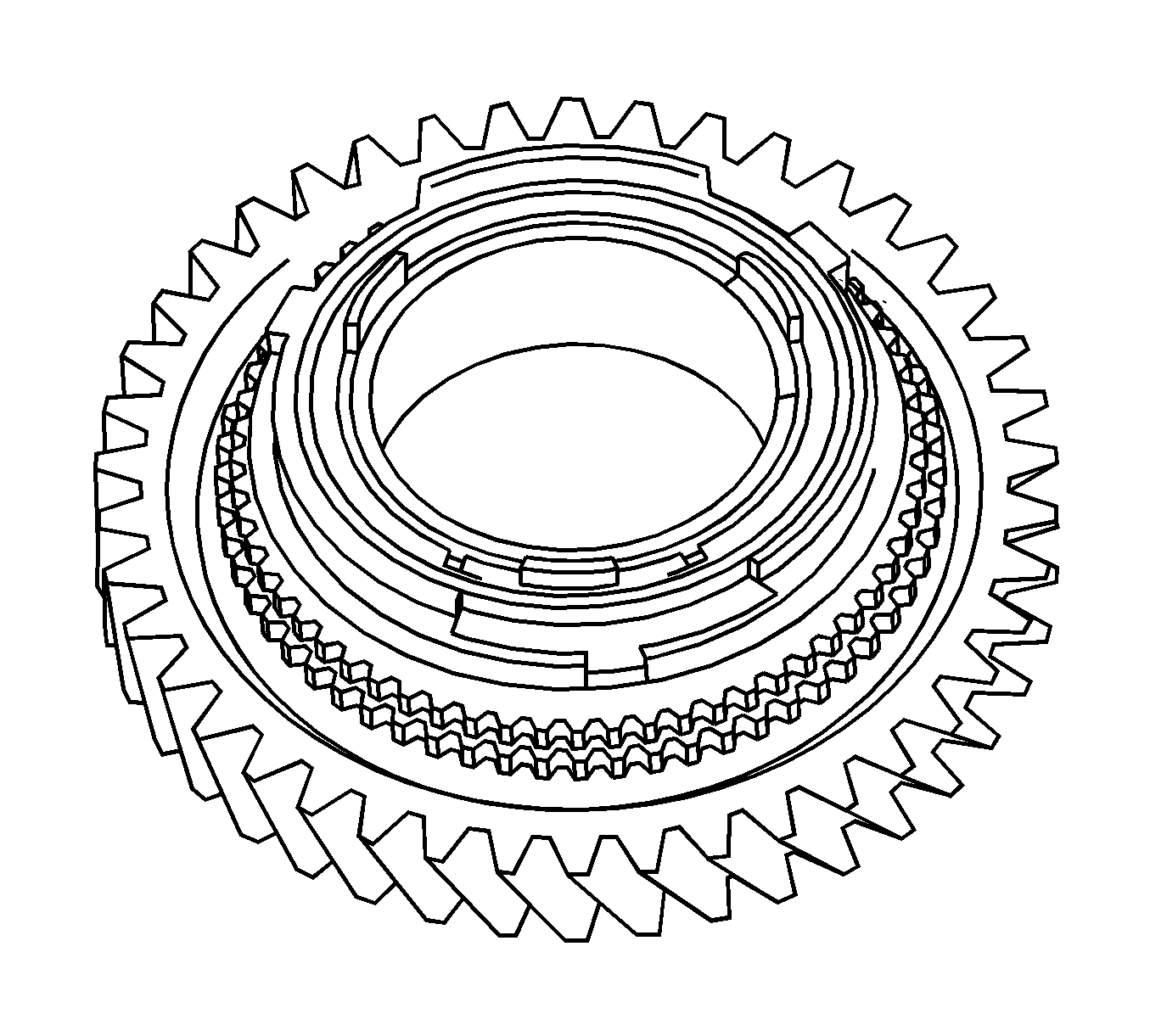
- Coat the 3rd gear cone with gear oil. Turn the synchronizer outer ring in one direction while pushing it against the 3rd gear cone. Check that the ring locks.
- Using a feeler gage, measure the clearance between the No. 3 synchronizer ring back and 3rd gear spline end.
- If the clearance is out of specification, replace the No. 3 synchronizer ring.
- Inspect the sliding condition between the No. 2 transmission hub sleeve and No. 2 transmission clutch hub.
- Inspect the tip of the spline gear on the No. 2 transmission hub sleeve for wear. If any defects are found, replace the transmission hub sleeve or the transmission clutch hub.
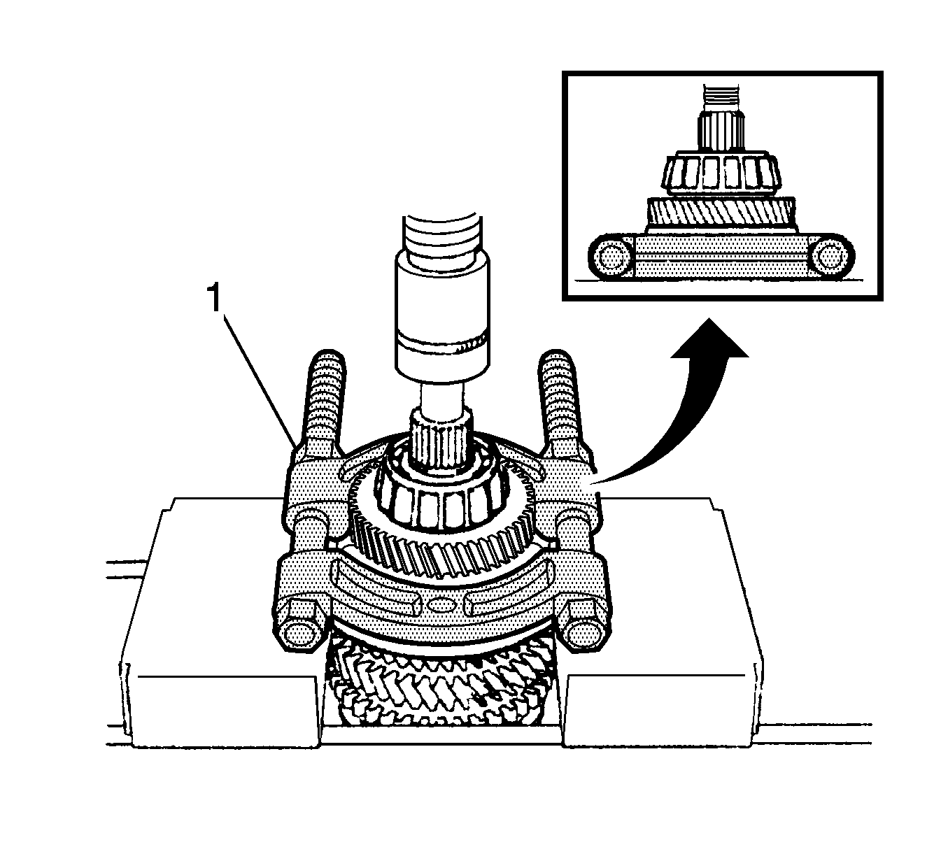
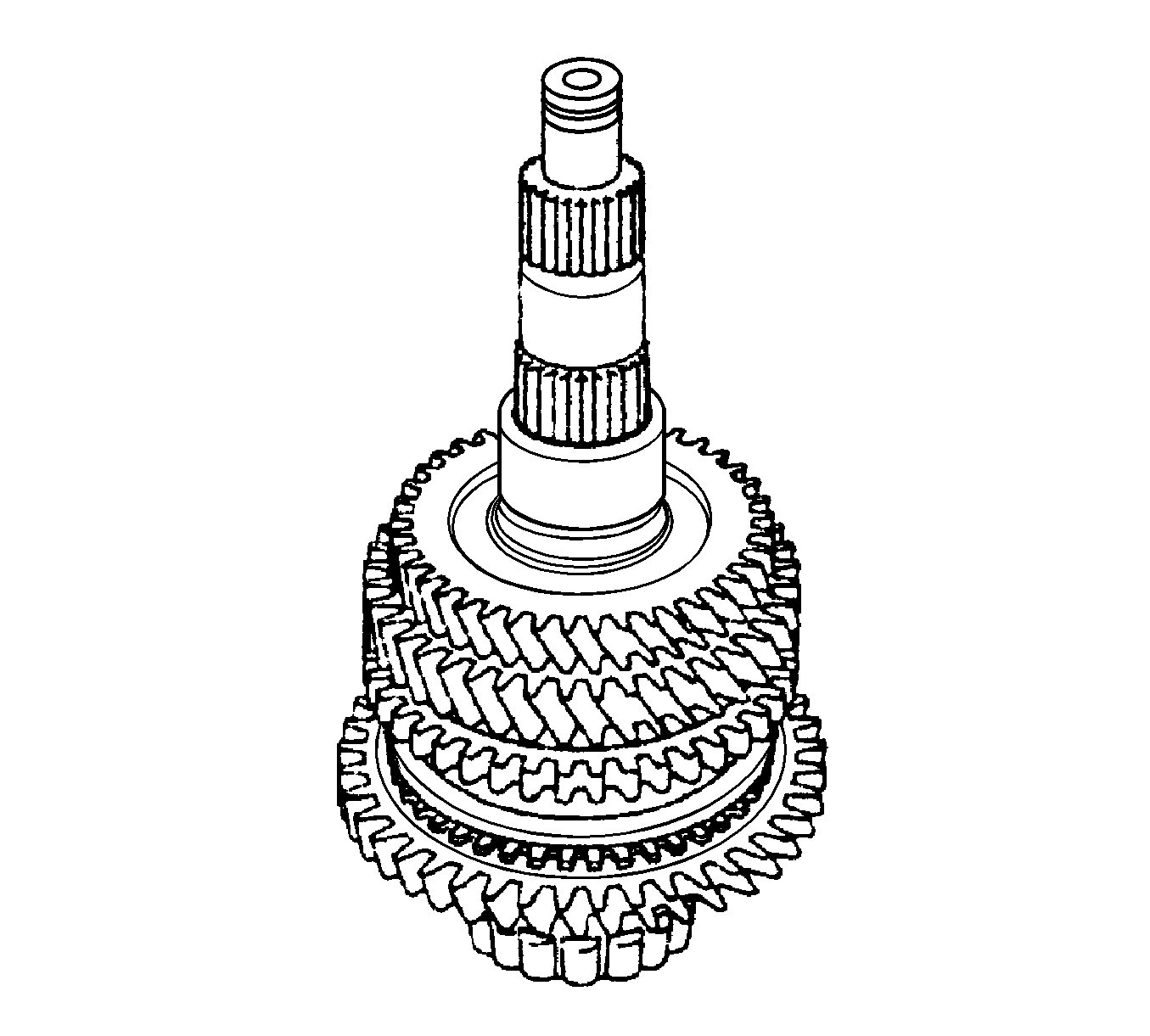
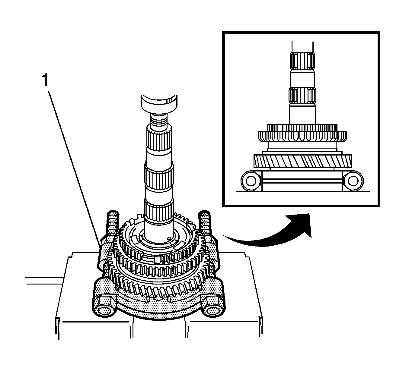
- Using a press (1), remove the output shaft rear bearing (inner race) and 4th driven gear.
- Remove the output gear spacer from the output shaft.
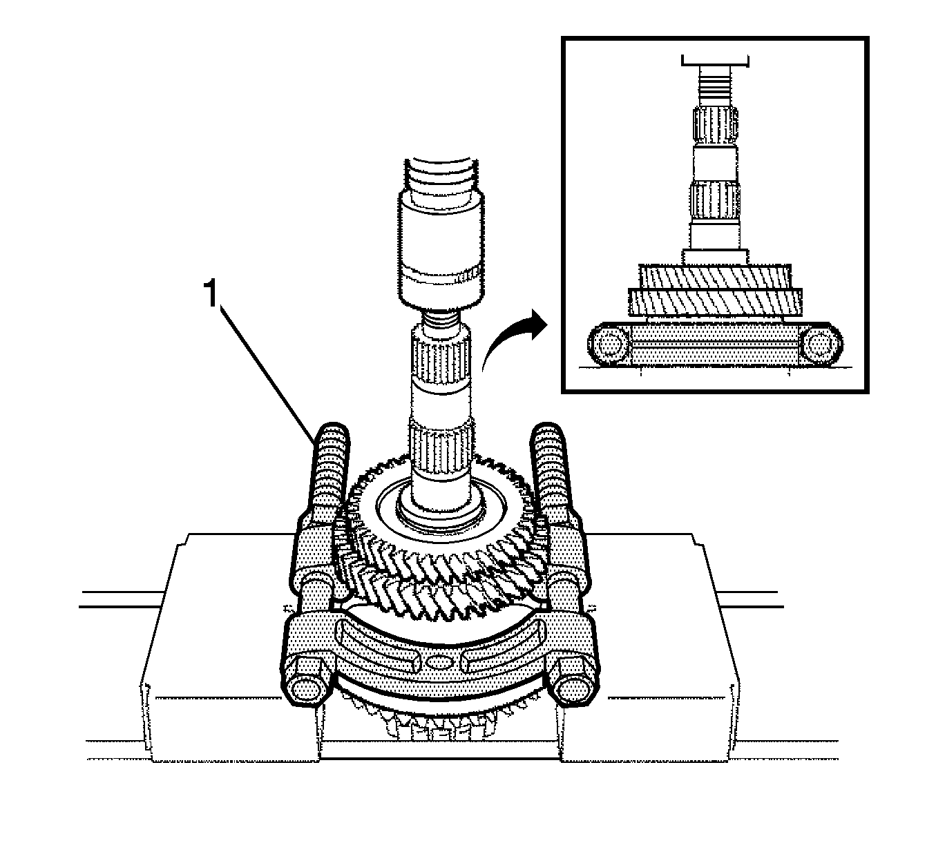
- Using a press (1), remove the 3rd driven gear and 2nd gear from the output shaft.
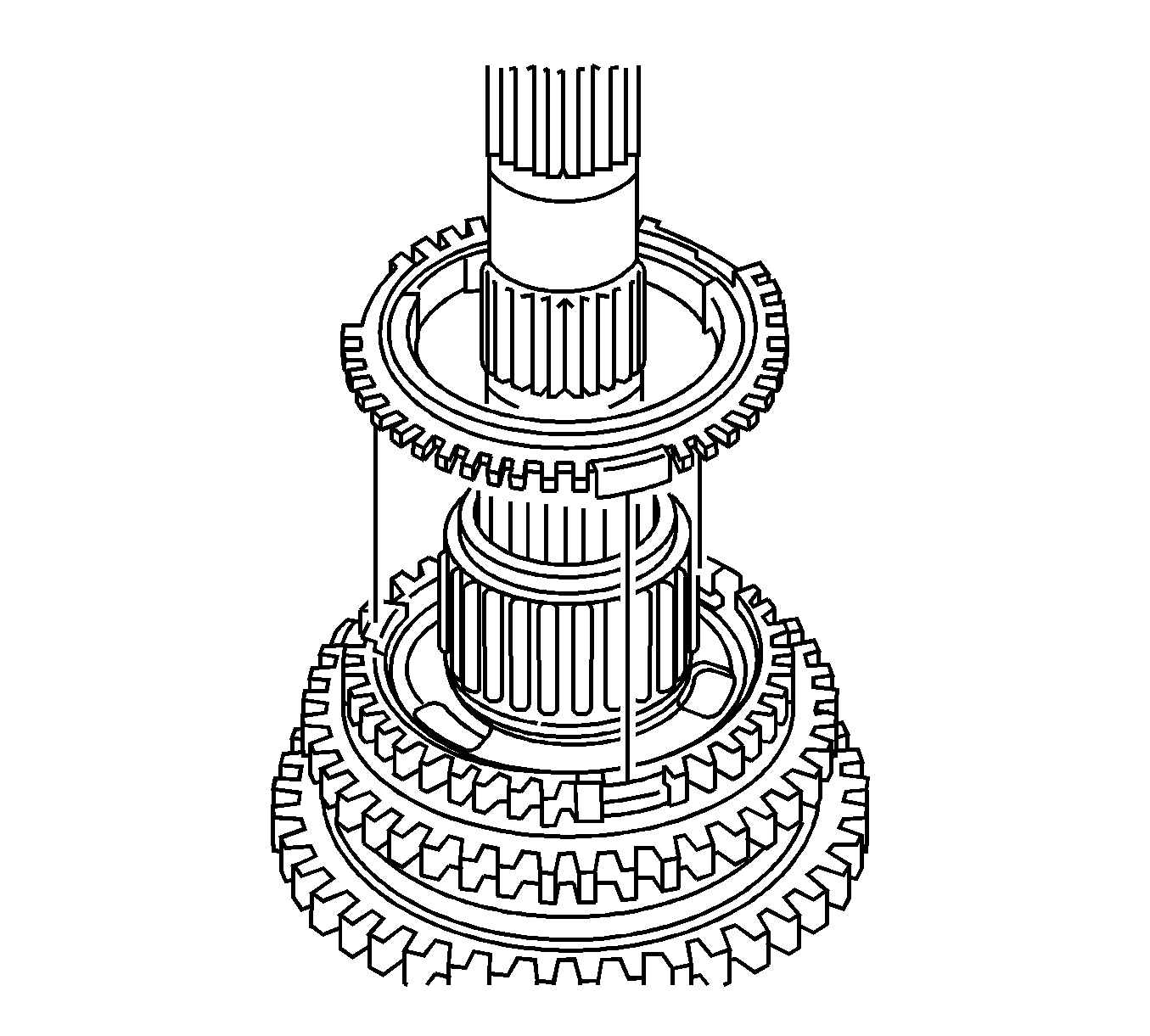
- Remove the No. 2 synchronizer ring set from the No. 1 transmission clutch hub.
- Remove the 2nd gear needle roller bearing from the output shaft.
- Remove the 2nd gear bearing spacer from the output shaft.
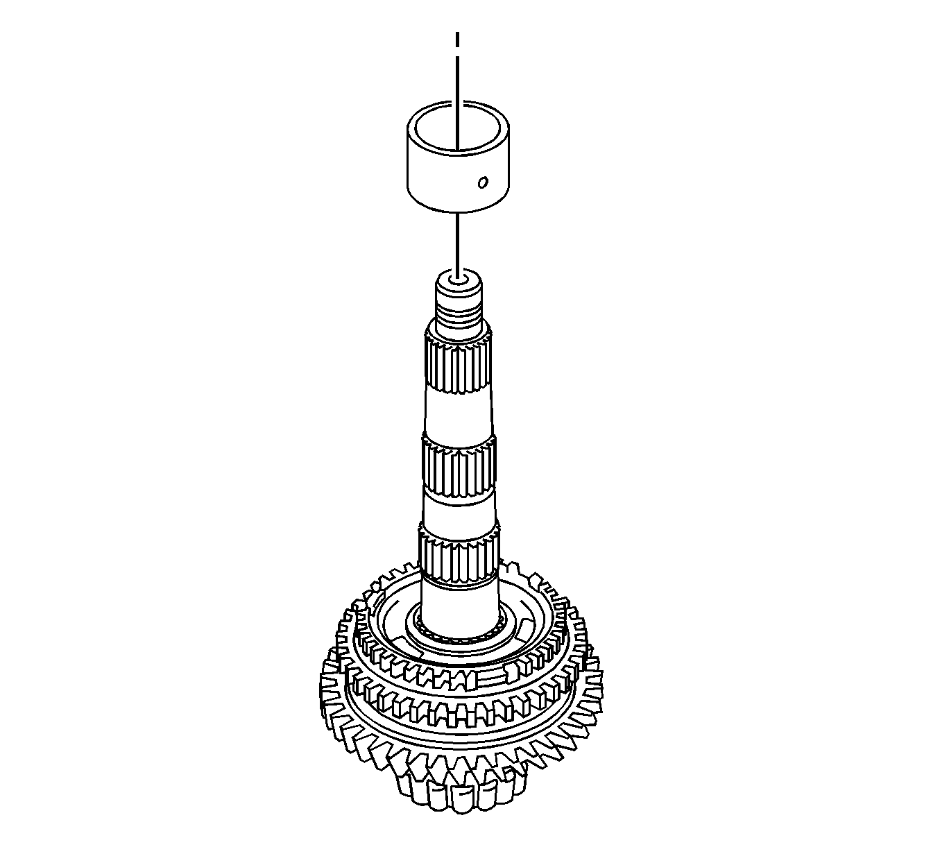
- Remove the 2nd gear bushing from the output shaft.
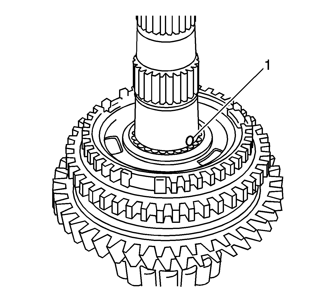
- Using a magnetic pick-up tool, remove the 2nd gear bushing ball (1) from the output shaft.
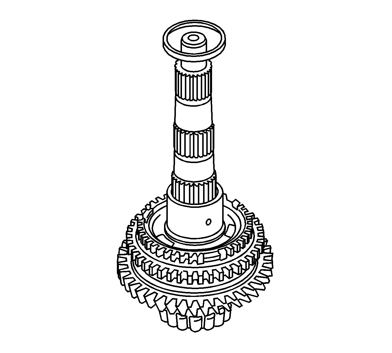
- Using a press (1), remove the No. 1 transmission clutch hub and 1st gear from the output shaft.
- Remove the No. 1 synchronizer ring set from the 1st gear.
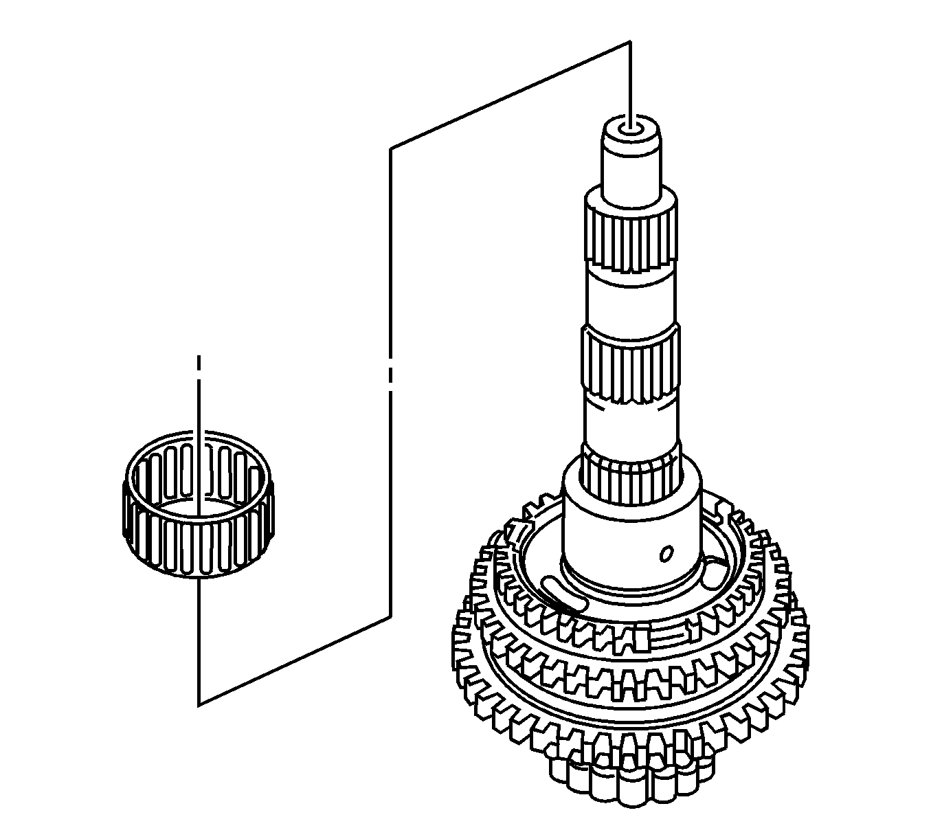
- Remove the 1st gear needle roller bearing from the output shaft.
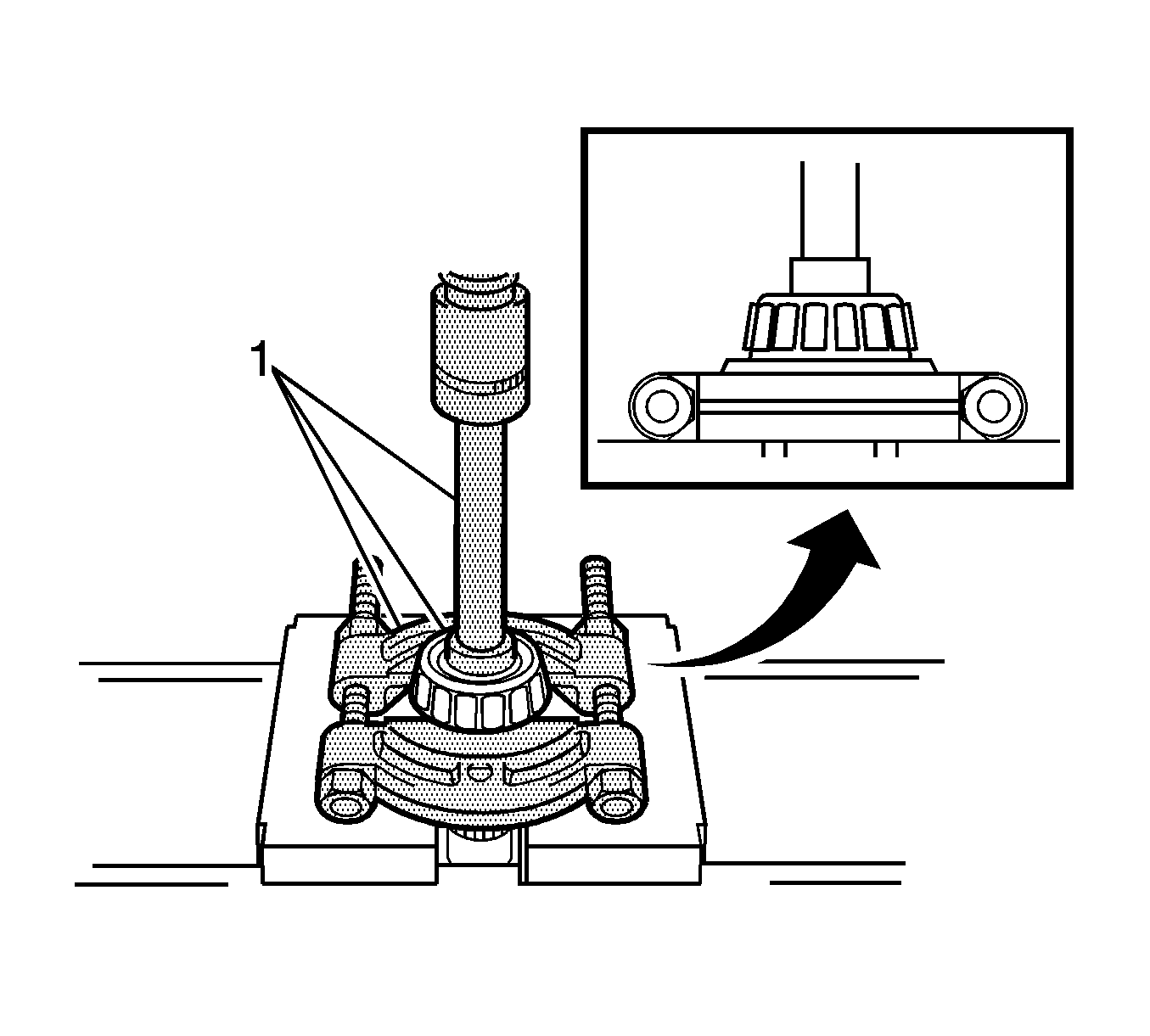
- Using a press (1), remove the output shaft front bearing (inner race) from the output shaft.
- Remove the No. 1 transmission clutch hub, No. 1 synchromesh shifting keys, and No. 1 synchromesh shifting key springs from the reverse gear.
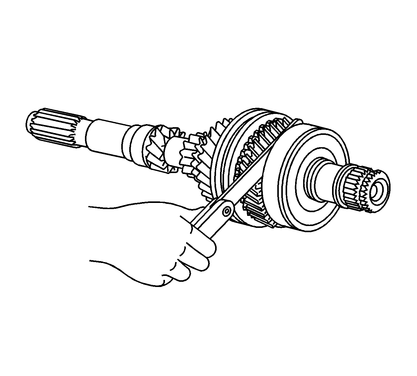
- Using a feeler gage, measure the 1st gear thrust clearance.
- If the clearance is out of specification, replace the 1st gear, or No. 1 transmission clutch hub.
- Using a dial indicator, measure the 2nd gear thrust clearance.
- Using V-blocks and a dial indicator, inspect the shaft for runout.
- If runout exceeds the maximum, replace the input shaft.
- Using a cylinder gage, measure the inside diameter of the 2nd gear.
- If the inside diameter exceeds the maximum, replace the 2nd gear.
- Using a cylinder gage, measure the inside diameter of the 1st gear.
- If the inside diameter exceeds the maximum, replace the 1st gear.
- Coat the 2nd gear cone with gear oil.
- Check for wear and damage.
- Turn the synchronizer ring set in one direction while pushing it against the 2nd gear cone.
- Check that the ring locks.
- Using a feeler gage, measure the clearance between the synchronizer ring and the gear spline end.
- If the clearance is less than the minimum, replace the synchronizer ring set.
- Coat the 1st gear cone with gear oil.
- Check for wear and damage.
- Turn the synchronizer ring set in one direction while pushing it against the 1st gear cone.
- Check that the ring set locks.
- Using a feeler gage, measure the clearance between the synchronizer ring and the gear spline end.
- If the clearance is less than the minimum, replace the synchronizer ring set.
- Using vernier calipers, measure the width of the reverse gear groove and thickness of the claw part on the No. 1 gear shift fork, and calculate the clearance.
- If the clearance is out of specification, replace the reverse gear and No. 1 gear shift fork with new ones.
- Check the sliding condition between the No. 1 transmission clutch hub and the reverse gear.
- Check the tip of the spline gear on the sleeve of the reverse gear for wear.
- Remove the speedometer drive gear from the front differential case assembly.
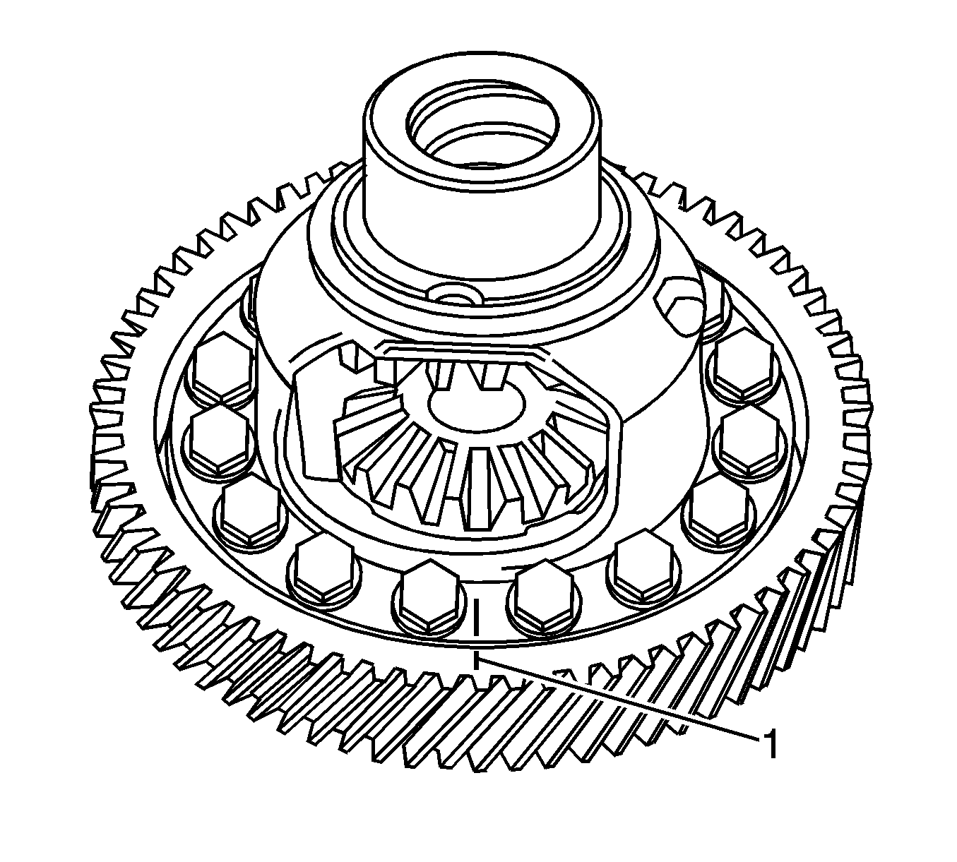
- Put matchmarks (1) on the front differential ring gear and the front differential case.
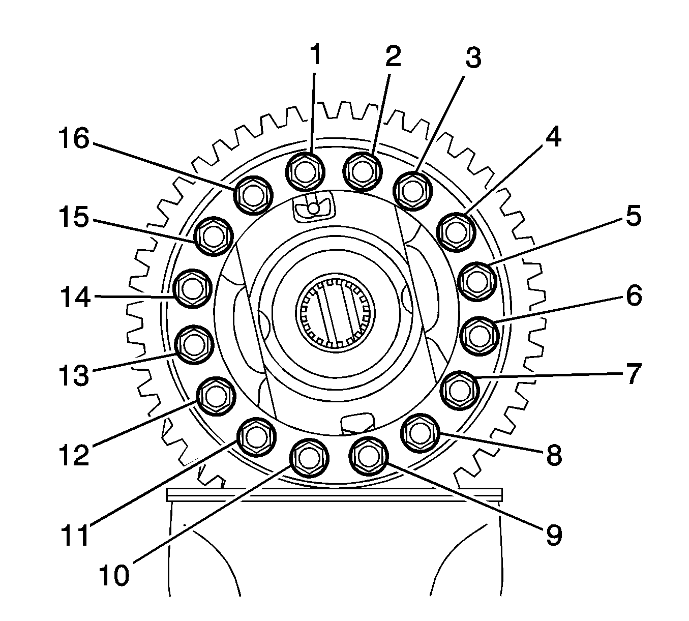
- Remove the bolts (1-16).
- Using a plastic hammer, remove the front differential case.
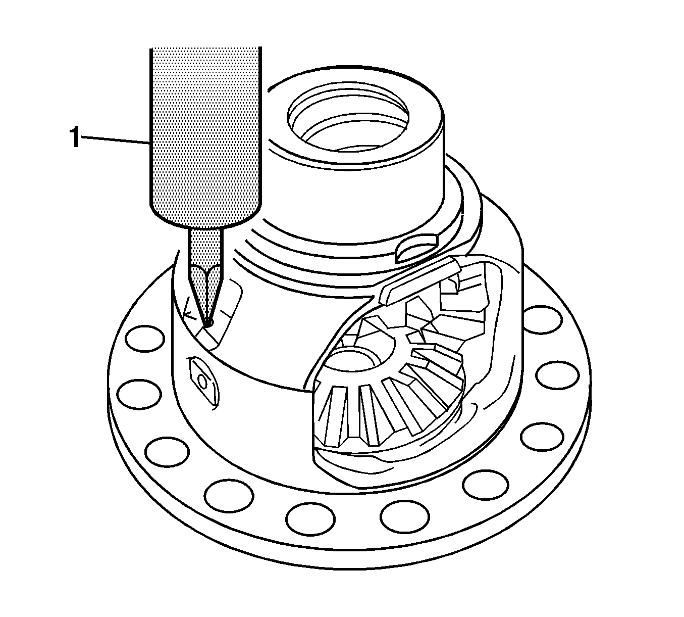
- Using a suitable tool (1), unstake the staked part of the front differential case.
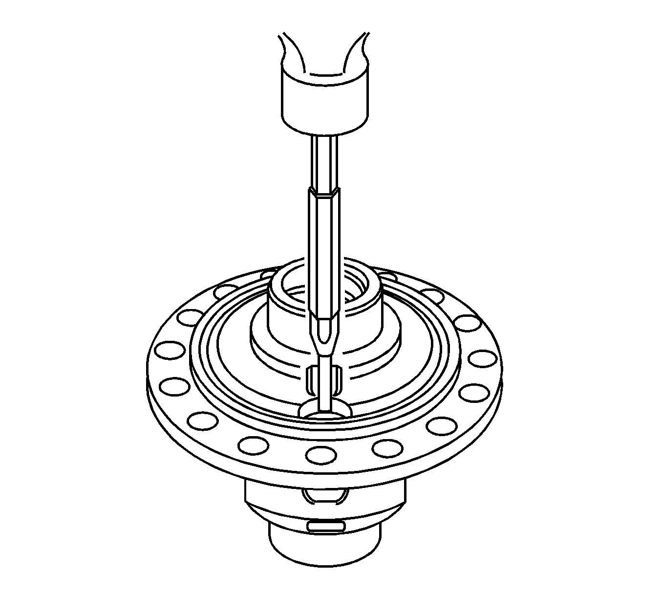
- Using a pin punch and a hammer, remove the front differential pinion shaft straight pin from the front differential case.
- Remove the No. 1 front differential pinion shaft from the front differential case.
- Remove the front differential pinions, front differential pinion thrust washers, front differential side gears, and front differential side gear thrust washers from the front differential case.
- Hold the front differential pinion to the front differential case side. Using a dial indicator, measure the front differential side gear backlash.
- If the backlash is out of specification, install proper side gear thrust washers.
- Using a micrometer, measure the thickness of the front differential pinion thrust washer.
- If the thickness is less than the minimum, replace the front differential pinion thrust washer.
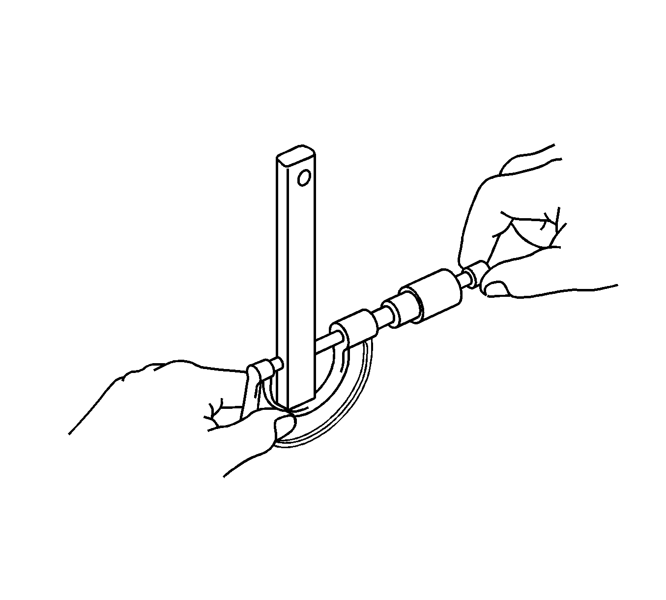
- Using a micrometer, measure the outside diameter of the No. 1 front differential pinion shaft.
- If the outer diameter is less than the minimum, replace the No. 1 front differential pinion shaft.
Specifications:
Standard clearance - 0.10-0.65 mm (0.0039-0.0256 in)
Specifications:
Standard clearance - 0.009-0.050 mm (0.0004-0.0020 in)
Specifications
| • | Standard inside diameter - 20.056-20.074 mm (0.7896-0.7903 in) |
| • | Maximum inside diameter - 20.074 mm (0.7903 in) |
Specifications
| • | Standard outside diameter - 19.984-20.000 mm (0.7868-0.7874 in) |
| • | Minimum outside diameter - 19.984 mm (0.7868 in) |
Specifications:
Standard clearance - 0.15-0.35 mm (0.0059-0.0138 in) (A-B)
Specifications
| • | Standard inside diameter - 34.981-34.997 mm (1.3772-1.3778 in) |
| • | Maximum inside diameter - 34.997 mm (1.3778 in) |
Specifications:
Standard clearance - 0.10-0.57 mm (0.0039-0.0224 in)
Specifications:
Standard clearance - 0.10-0.35 mm (0.0039-0.0138 in)
Specifications
| • | Standard clearance, KOYO made bearing - 0.009-0.053 mm (0.0004-0.0021 in) |
| • | Standard clearance, NSK made bearing - 0.009-0.051 mm (0.0004-0.0020 in) |
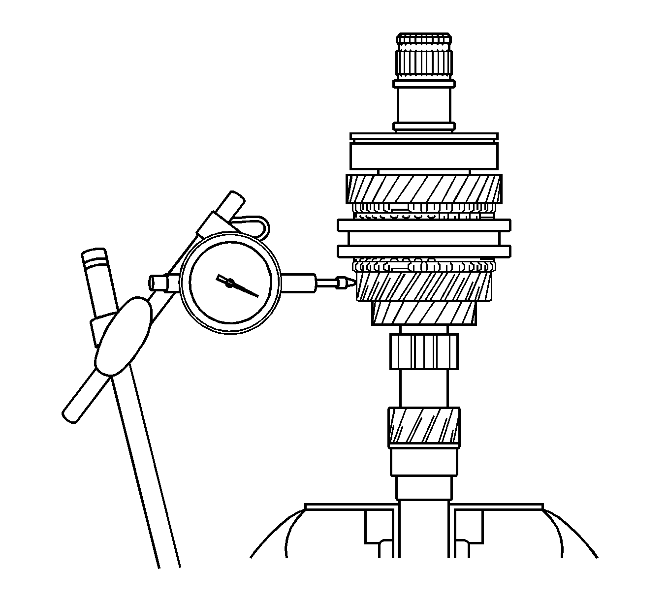
Specifications
| • | Standard clearance, KOYO made bearing - 0.009-0.053 mm (0.0004-0.0021 in) |
| • | Standard clearance, NSK made bearing - 0.009-0.051 mm (0.0004-0.0020 in) |
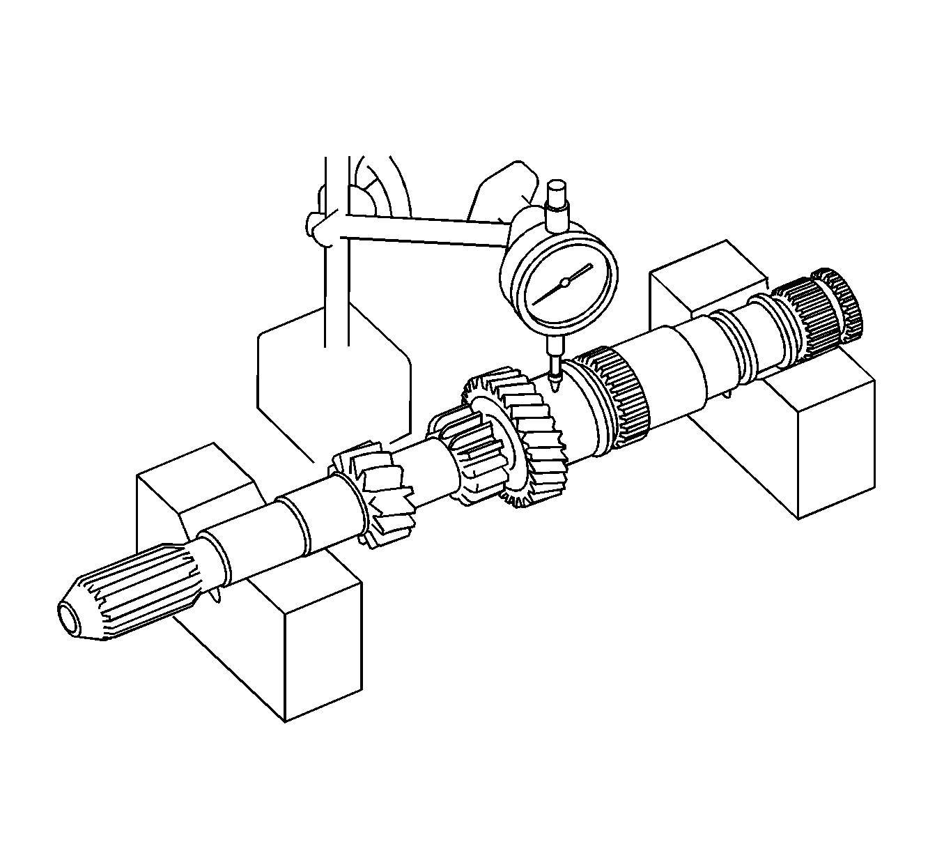
Specification
Maximum runout - 0.03 mm (0.0012 in)
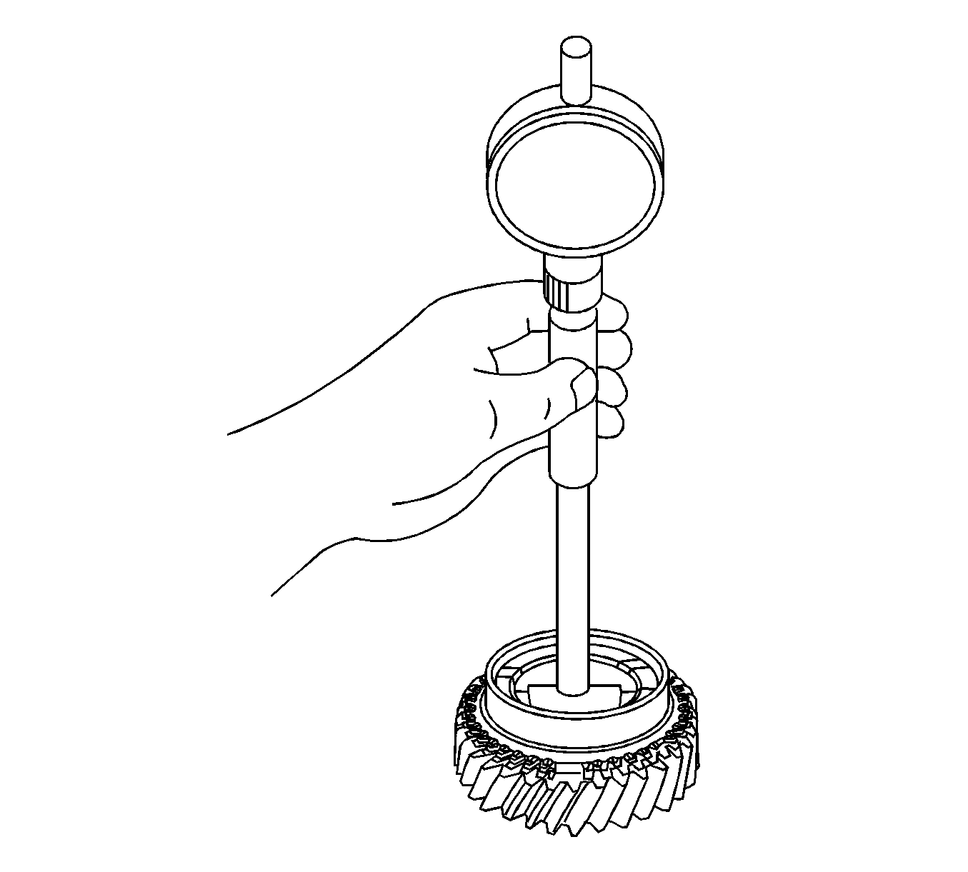
Specifications
| • | Standard inside diameter - 42.009-42.025 mm (1.6539-1.6545 in) |
| • | Maximum inside diameter - 42.025 mm (1.6545 in) |
Specifications
| • | Standard inside diameter - 43.009-43.025 mm (1.6933-1.6939 in) |
| • | Maximum inside diameter - 43.025 mm (1.6939 in) |
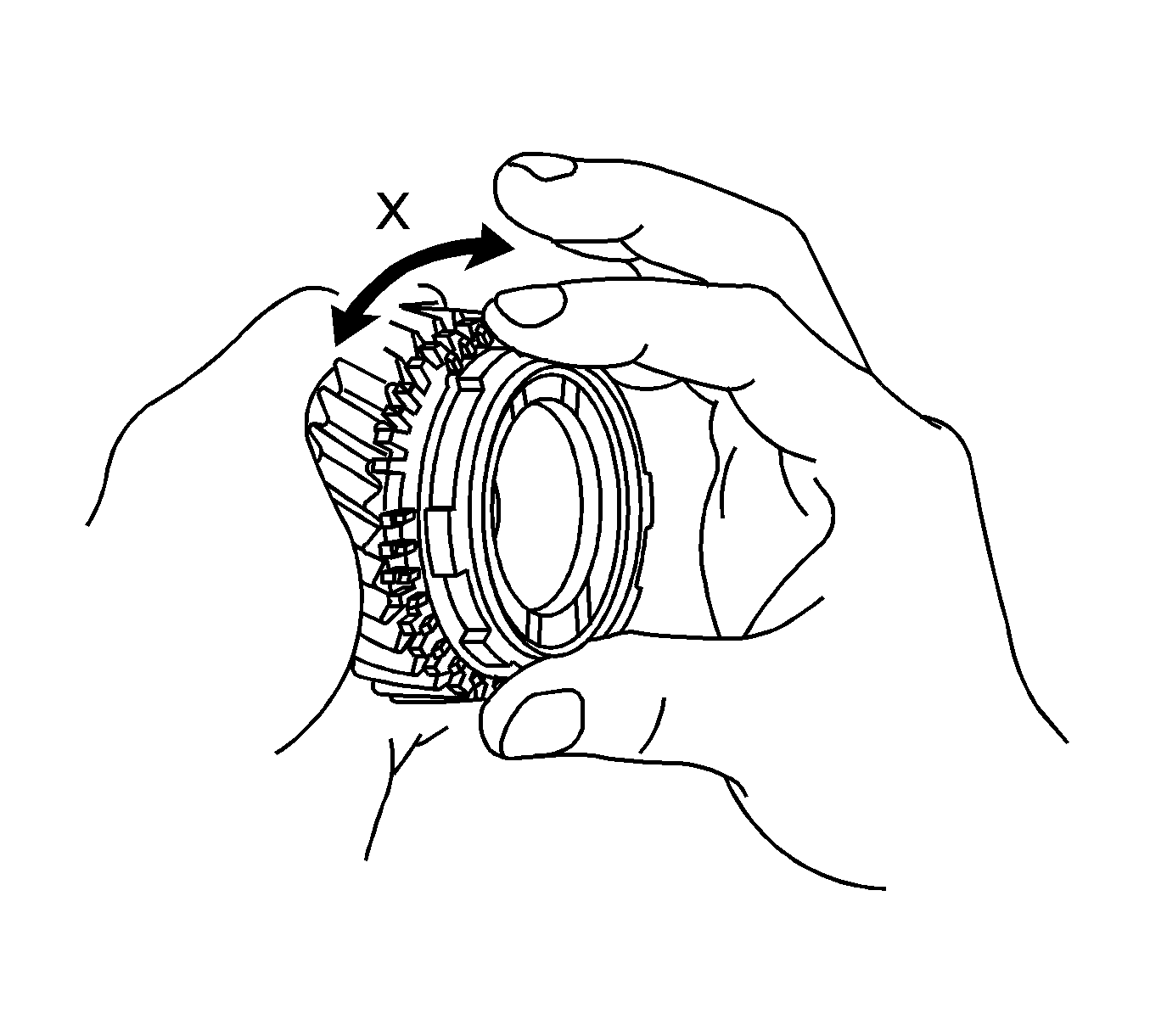
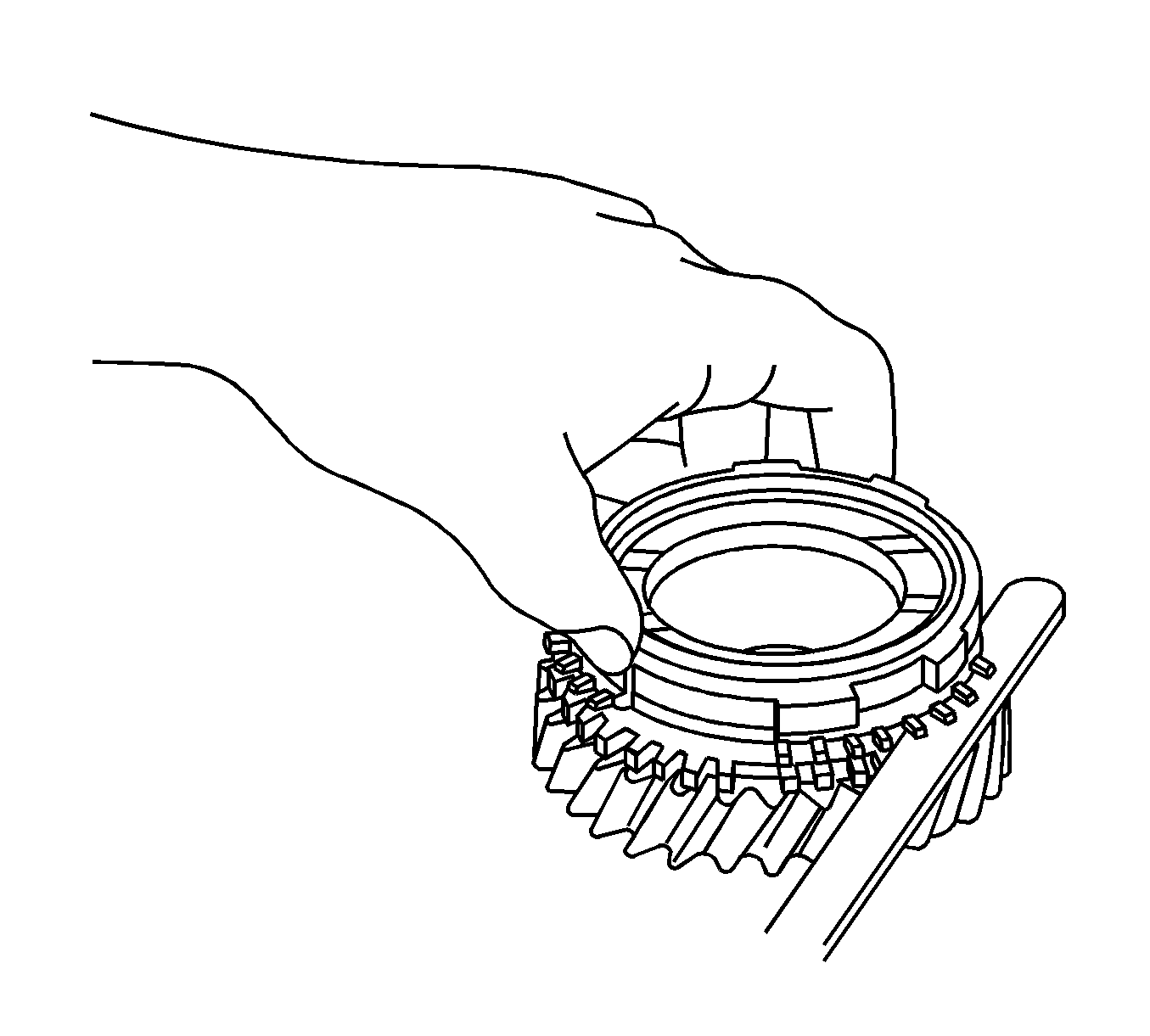
Specifications:
Standard clearance - 0.7-1.45 mm (0.0276-0.0570 in)
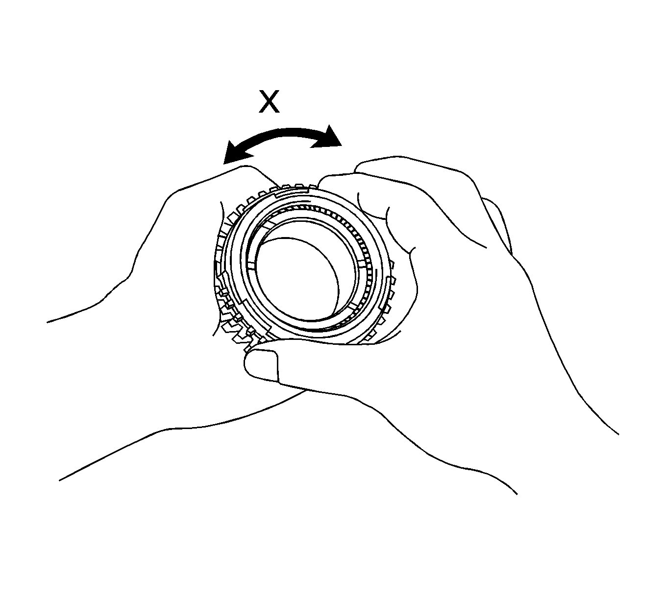
If the synchronizer outer ring does not lock, replace the ring or the 3rd gear.
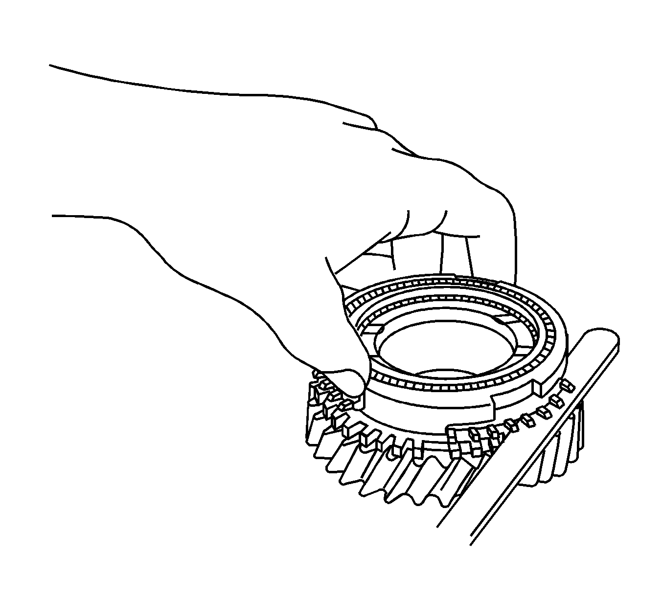
Specifications:
Standard clearance - 0.65-1.75 mm (0.0276-0.0689 in)
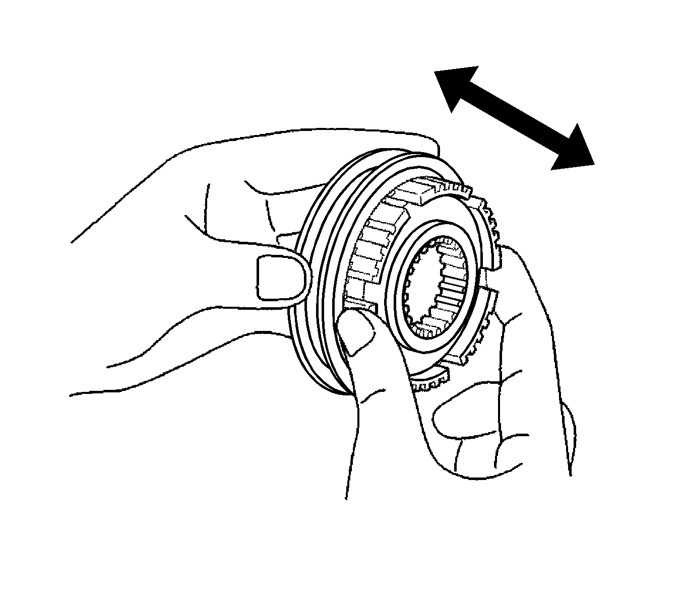
Specifications:
Standard clearance - 0.25-0.40 mm (0.0098-0.0157 in)
Specifications:
Standard clearance - 0.10-0.35 mm (0.0039-0.0138 in)
Specification
Maximum runout - 0.03 mm (0.0012 in)
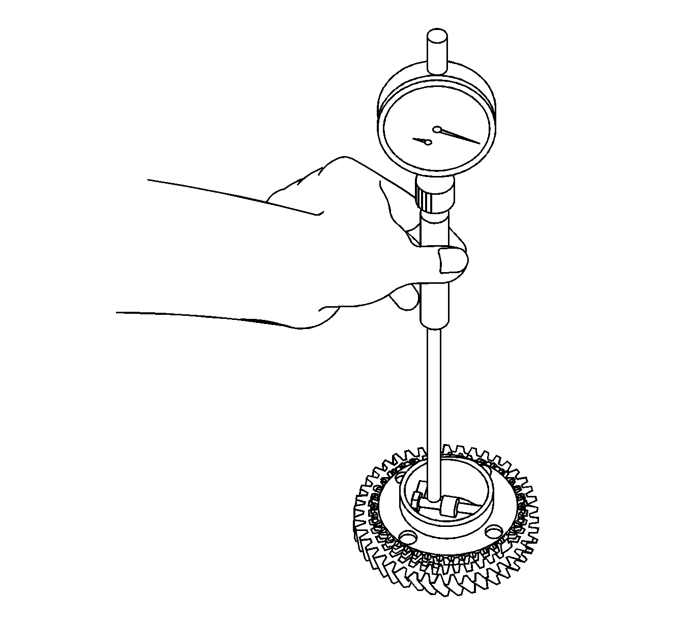
Specifications
| • | Standard inside diameter - 50.009-50.025 mm (1.9689-1.9695 in) |
| • | Maximum inside diameter - 50.025 mm (1.9695 in) |
Specifications
| • | Standard inside diameter - 51.009-51.025 mm (2.0082-2.0089 in) |
| • | Maximum inside diameter - 51.025 mm (2.0089 in) |
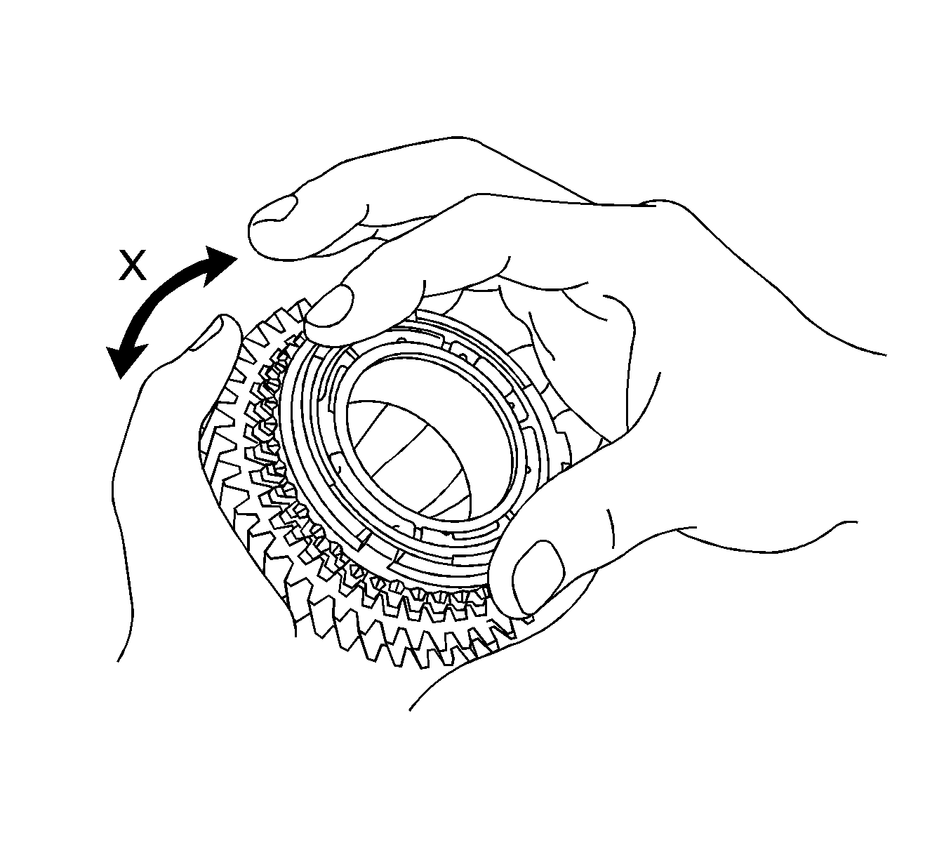
If the synchronizer ring set does not lock, replace the synchronizer ring set.
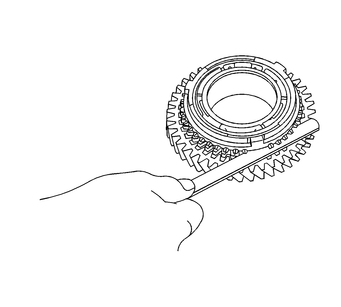
Specifications:
Standard clearance - 0.70-1.45 mm (0.0276-0.0571 in)
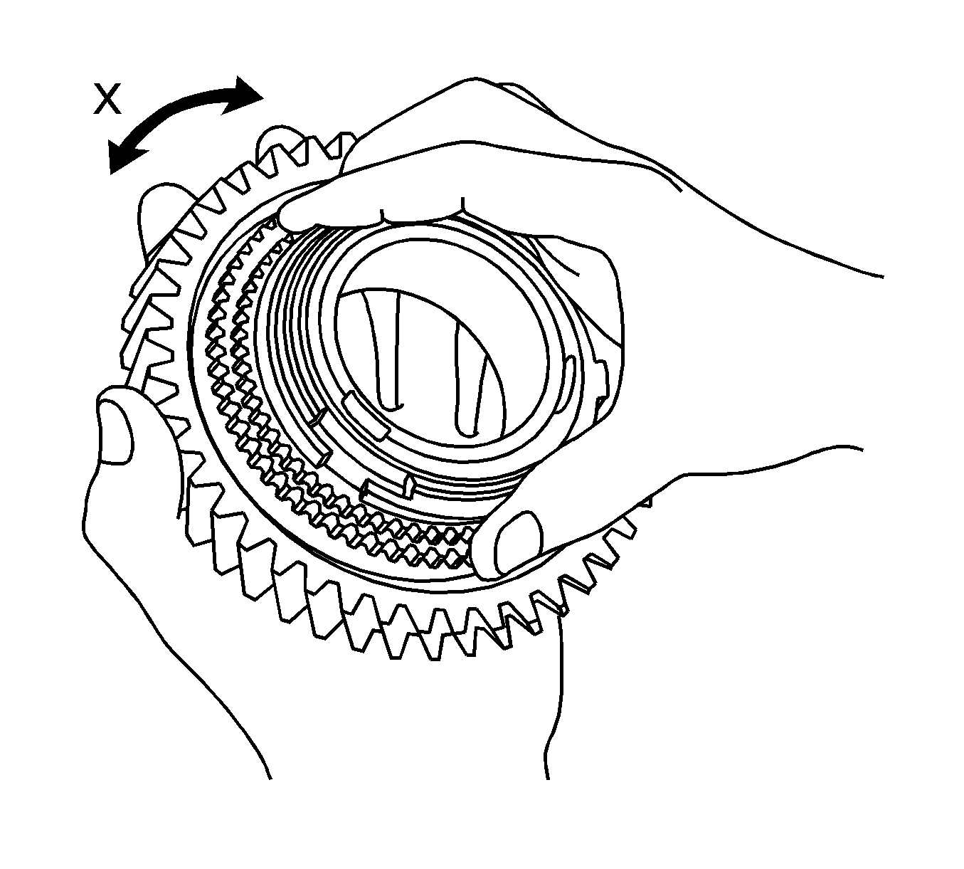
If the synchronizer ring set does not lock, replace the synchronizer ring set.
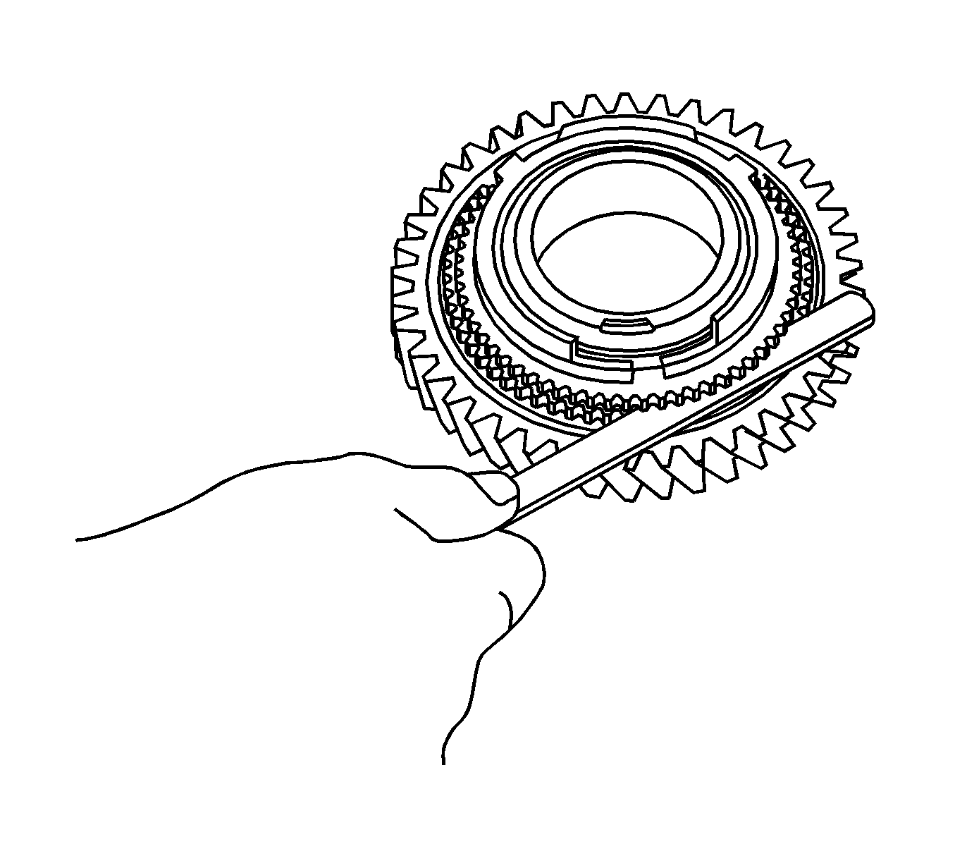
Specifications:
Standard clearance - 0.70-1.45 mm (0.0276-0.0571 in)
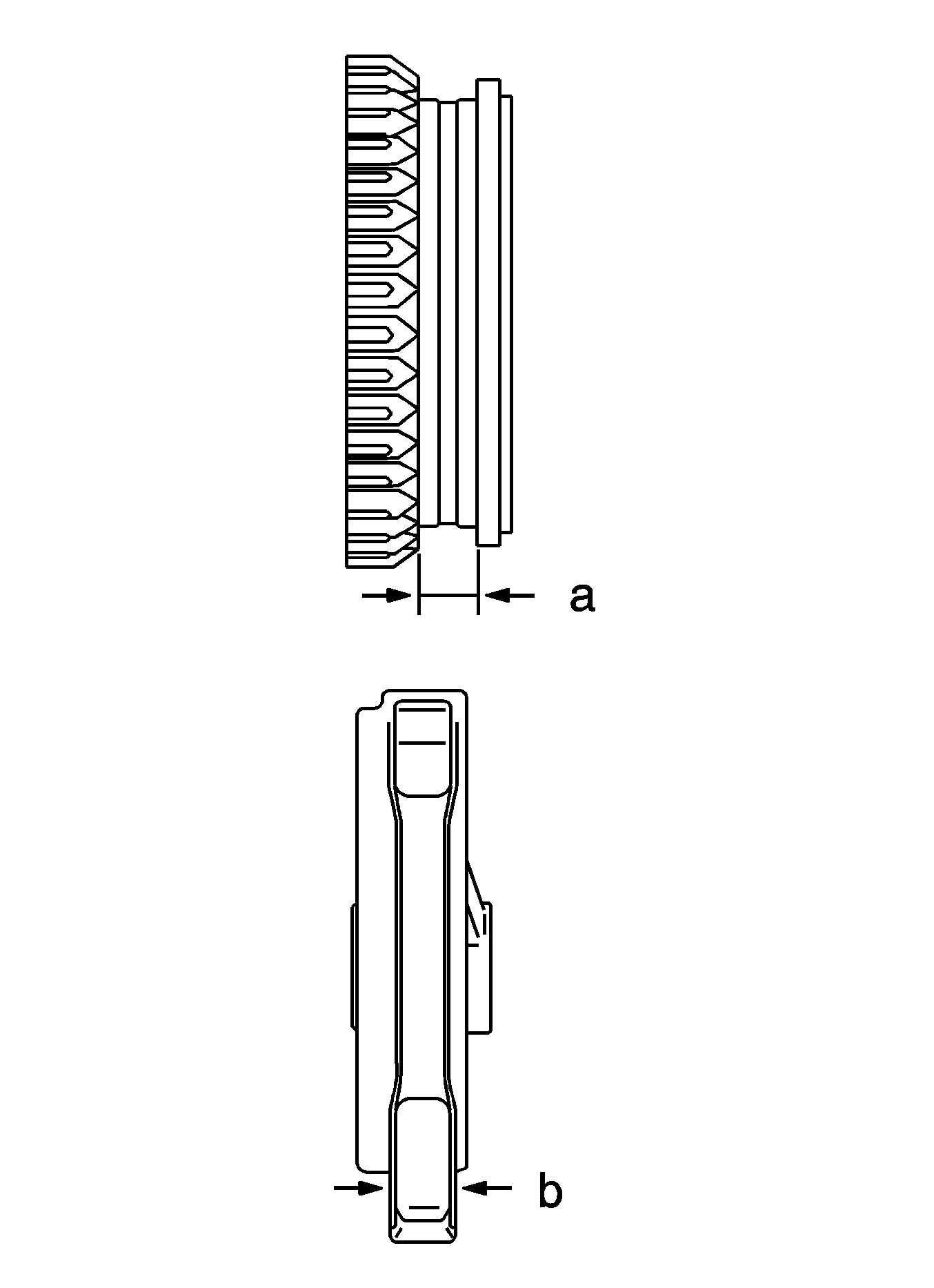
Specifications:
Standard clearance - 0.15-0.35 mm (0.0059-0.0138 in) (A-B)
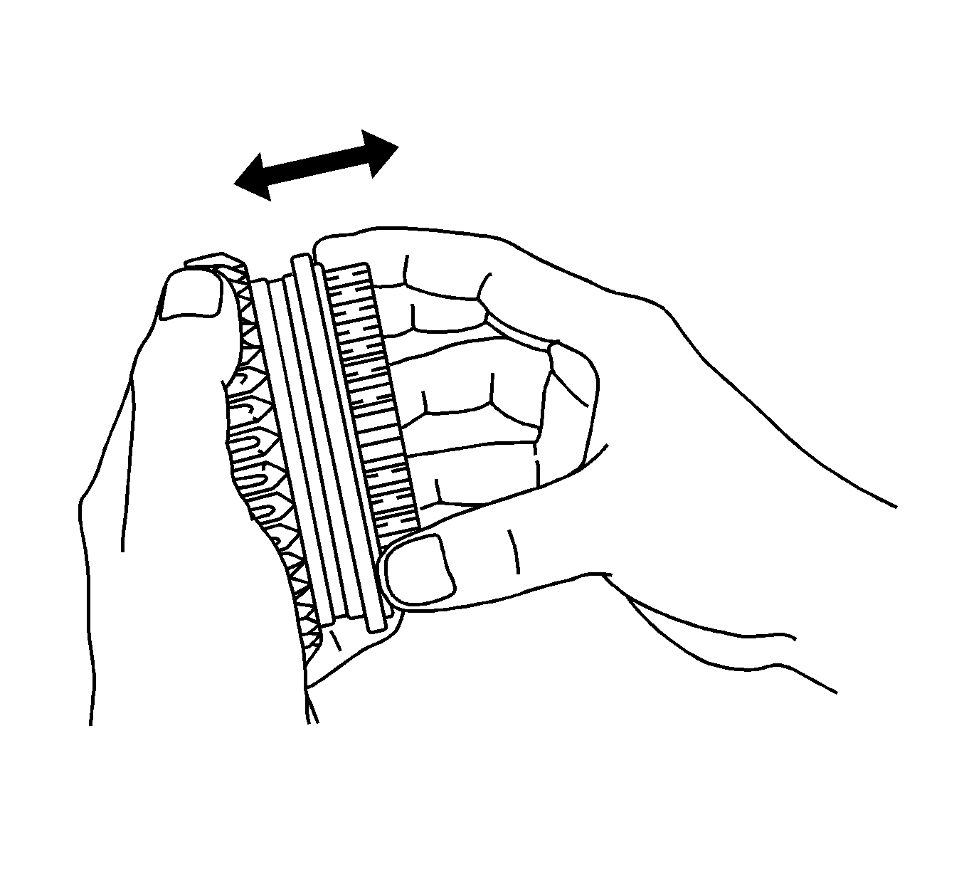
If any defects are found, replace the transmission hub sleeve or the transmission clutch hub.
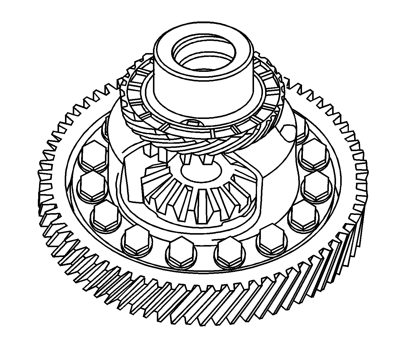
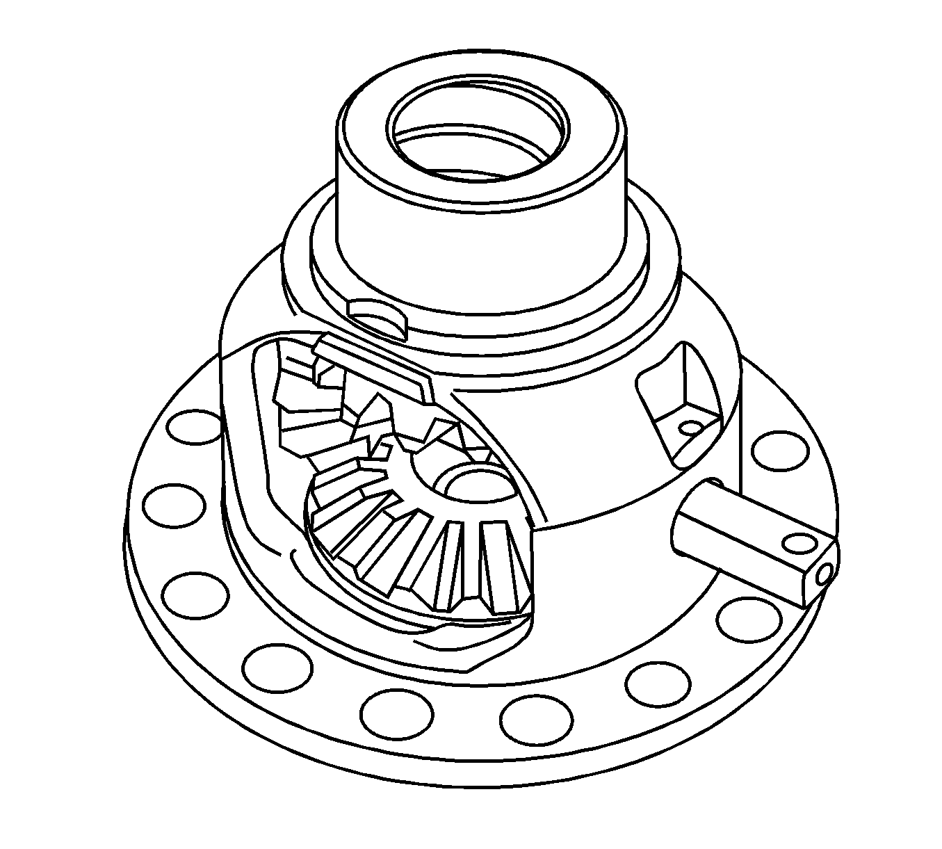
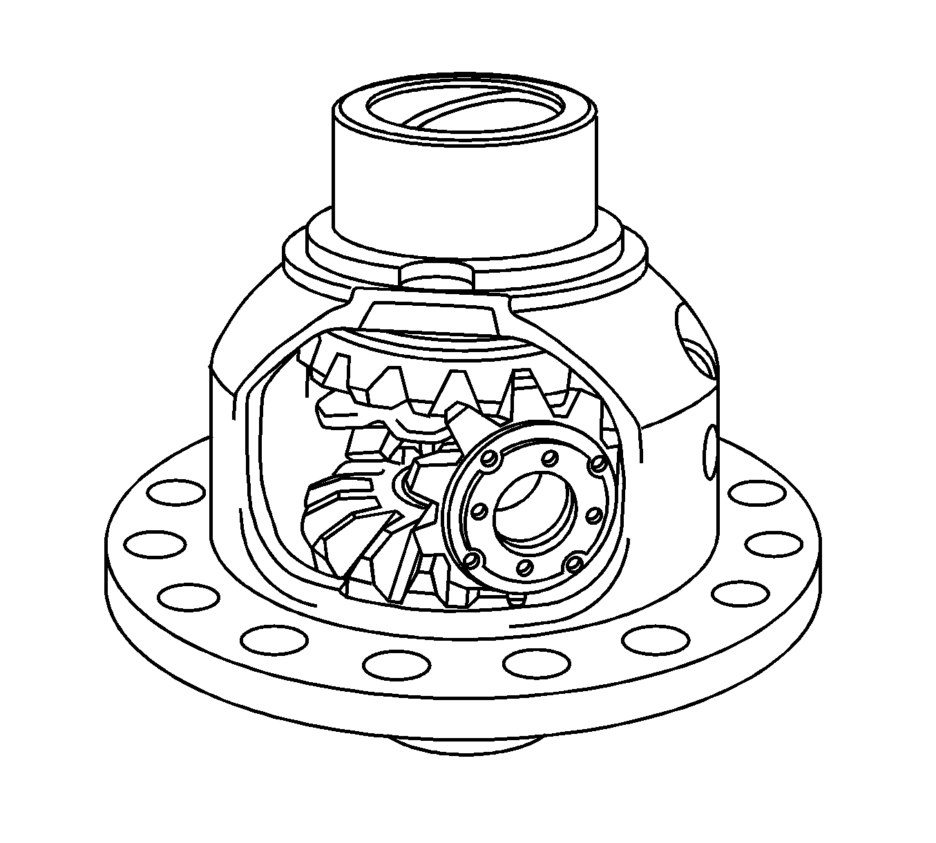
Remove the pinion thrust washers and side gear thrust washers while turning the front differential pinion.
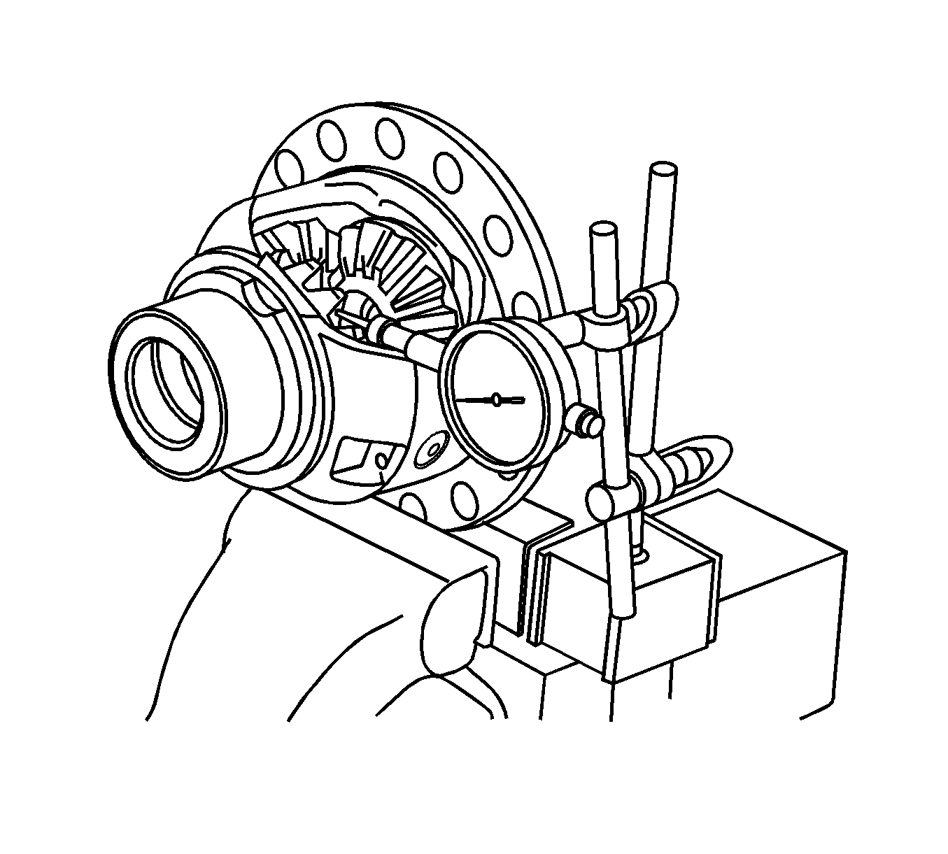
Specifications
Standard backlash - 0.05-0.20 mm (0.002-0.0079 in)
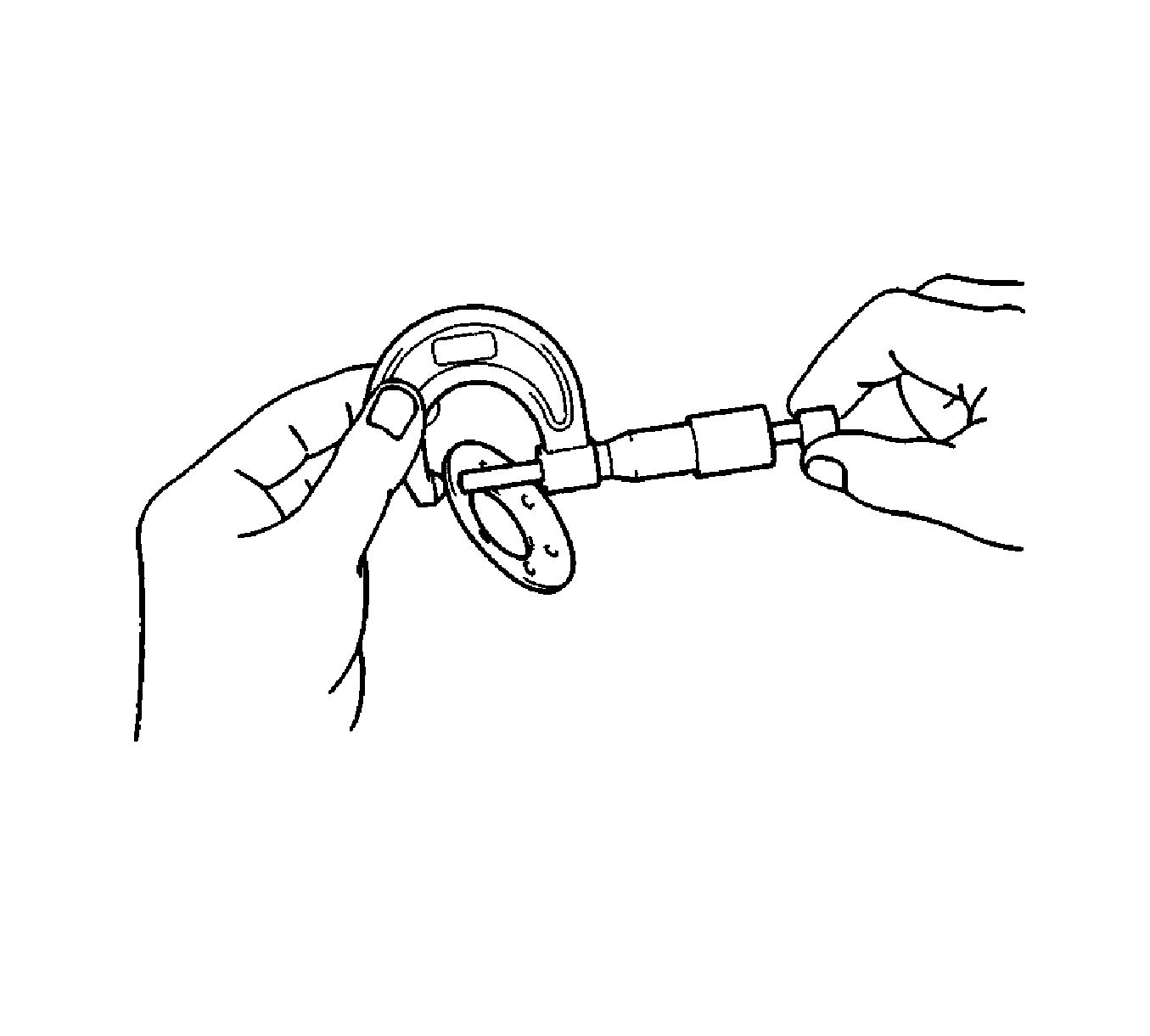
Specifications
Minimum thickness - 0.09 mm (0.035 in)
Specifications
Minimum diameter - 17.975 mm (0.7076 in)
