Tools Required
J 42572 Drive Shaft Boot Clamp Pliers
Disassembly Procedure
- Remove the large boot retaining clamp from the CV joint seal.
- Remove the small boot retaining clamp from the joint seal.
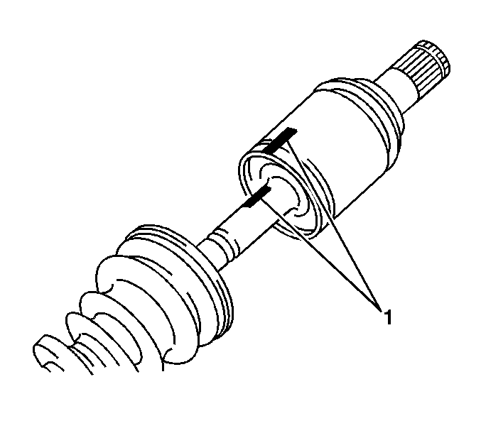
- Place reference marks on the inboard and outboard joint shafts.
- Pull out the inboard joint.
- Place reference marks on the outboard joint shaft, the inner race and cage.
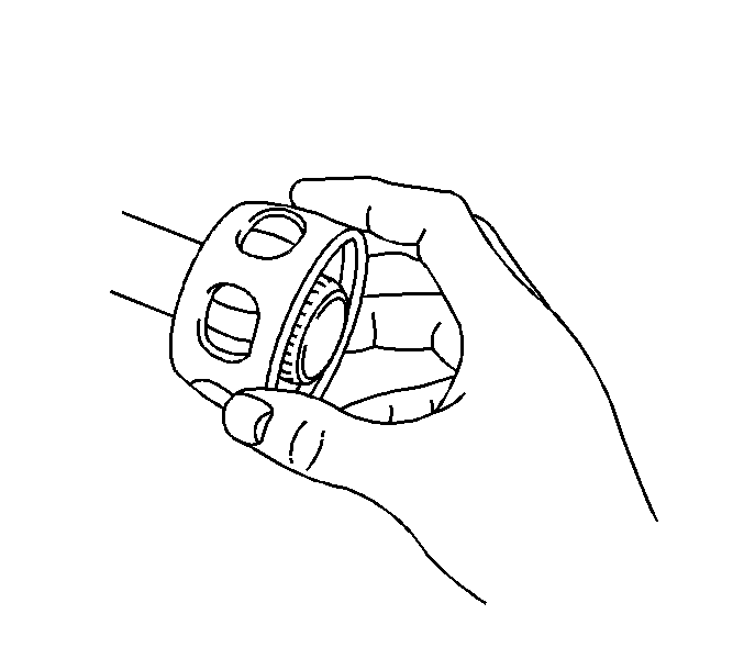
- Remove the 6 balls from the outboard joint shaft.
- Wipe the grease from the face of the joint inner race, cage, balls, etc.
- Slide the cage toward the outboard joint.
- Remove the snap ring.
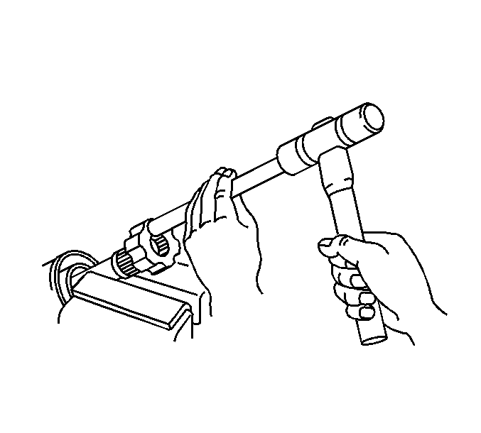
- Using a brass bar and hammer, remove the inner race from the shaft.
- Clean the following thoroughly with clean solvent:
- Thoroughly air dry all the parts.
Use a side cutter or other suitable tool and discard the clamp.
Use a side cutter or other suitable tool and discard the clamp.
Important: All traces of old grease and any contaminates must be removed.
| • | The inner race |
| • | The outer race |
| • | The cage |
| • | The balls |
| • | The axle shaft exposed end |
Assembly Procedure
Notice: Wheel drive shaft boots, seals and clamps should be protected from sharp objects any time service is performed on or near the wheel drive shaft(s). Damage to the boot(s), the seal(s) or the clamp(s) may cause lubricant to leak from the joint and lead to increased noise and possible failure of the wheel drive shaft.
- Temporarily install new outboard and inboard boots with new clamps on the outboard joint shaft.
- Install the cage to the outboard joint shaft.
- Using a brass bar and hammer, install the inner race on the outboard joint shaft.
- Install a new snap ring.
- Align the inboard joint shaft and outboard joint shaft.
- Insert approximately 60 percent of the grease from the service kit into the outer joint.
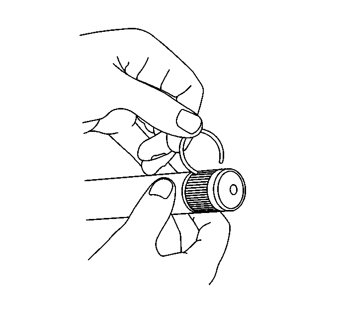
- Install a new retaining ring to the axle shaft.
- Install the boots into the shaft grooves.
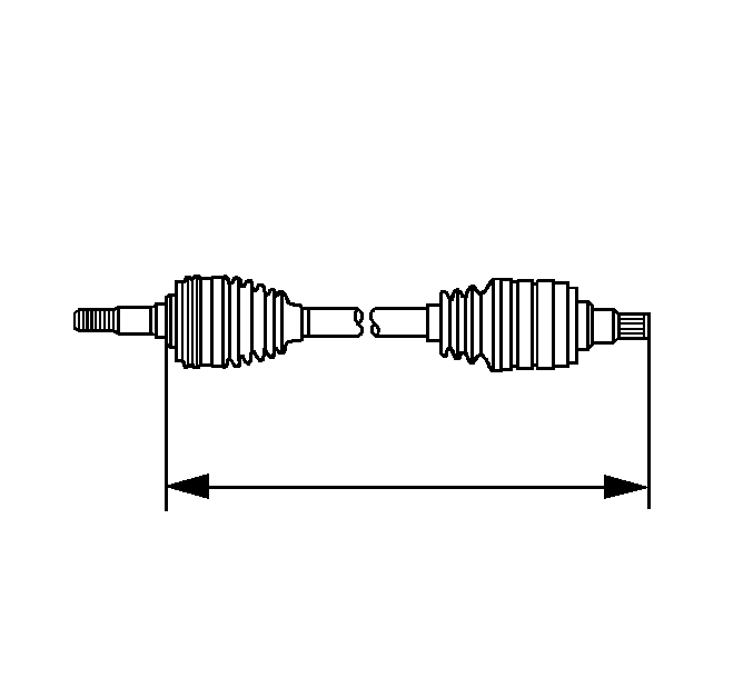
- Ensure that the drive shaft is at standard length.
- Position the small boot retaining clamp onto the neck of the boot.
- Position the small boot and small retaining clamp to the axle shaft.
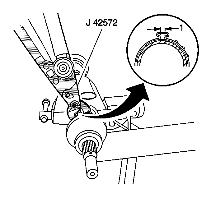
- Using the J 42572 , crimp the small boot retaining clamp.
- Position the large boot retaining clamp onto the boot.
- Position the boot and large retaining clamp to the joint outer race.
- Inspect the boot for proper shape.
- Inspect the boot for damage.
- Using the J 42572 , crimp the large boot retaining clamp.
- Inspect the outer CV joint and wheel drive shaft for smooth operation. This will also distribute the grease within the joint.
Important: Before installing the boots, wrap the spline of the outboard joint with vinyl tape to prevent possible tearing of the boots.
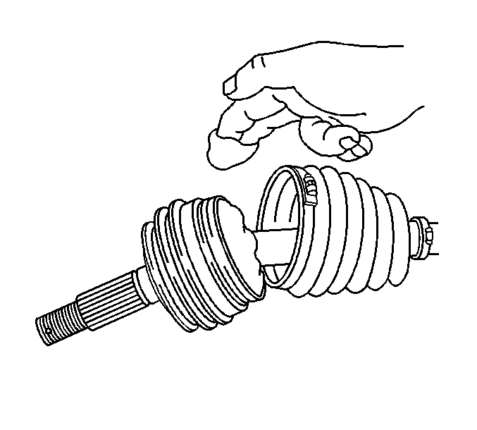
Important: The grease capacity of the outboard joint is approximately 71-81g (2.5-2.9 oz) which is yellow in color. The inboard joint grease capacity is approximately 132-142g (4.7-5.0 oz) which is gray in color.
| 6.1. | Spread the grease onto the ball tracks, the balls, the cage and the inner race. |
| 6.2. | Spread the remainder of the grease into the bottom of the outer race. |
| 6.3. | Insert the remaining grease from the service kit into the boot. |
Specification
The standard length is approximately 688.33-698.33 mm (27.098-27.492 in).
Notice: Use the correct fastener in the correct location. Replacement fasteners must be the correct part number for that application. Fasteners requiring replacement or fasteners requiring the use of thread locking compound or sealant are identified in the service procedure. Do not use paints, lubricants, or corrosion inhibitors on fasteners or fastener joint surfaces unless specified. These coatings affect fastener torque and joint clamping force and may damage the fastener. Use the correct tightening sequence and specifications when installing fasteners in order to avoid damage to parts and systems.
Important: The boot must not be dimpled, stretched or out of shape in any way.
If the boot is NOT shaped correctly, equalize the pressure in the boot by lifting the boot edge slightly and shape the boot properly by hand.
If the boot has been cut or punctured during assembly, you must discard and replace the boot.
Important: The boot retaining clamp must not be over-tightened or under-tightened.
| 18.1. | Hold the wheel drive shaft vertically, with the outer joint at the bottom. |
| 18.2. | Rotate the wheel drive shaft 4 or 5 times in a circular motion. |
