Tools Required
| • | J 8001 Dial Indicator Set |
| • | J 22912-B Split Plate Bearing Puller |
Removal Procedures
- Raise and support the vehicle. Refer to Lifting and Jacking the Vehicle in General Information.
- Remove the propeller shaft. Refer to Two-Piece Propeller Shaft Replacement in Propeller Shaft.
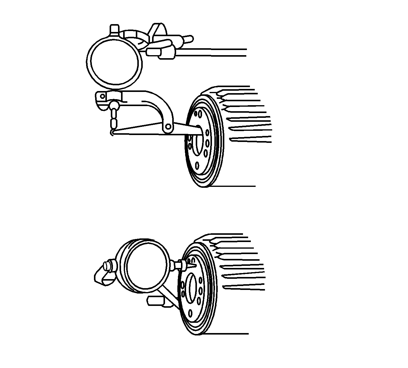
- Check the coupling runout using J 8001
- Observe the dial indicator and check the vertical runout. Maximum vertical runout is 0.05 mm (0.002 in).
- Observe the dial indicator and check the horizontal runout. Minimum horizontal runout is 0.05 mm (0.002 in).
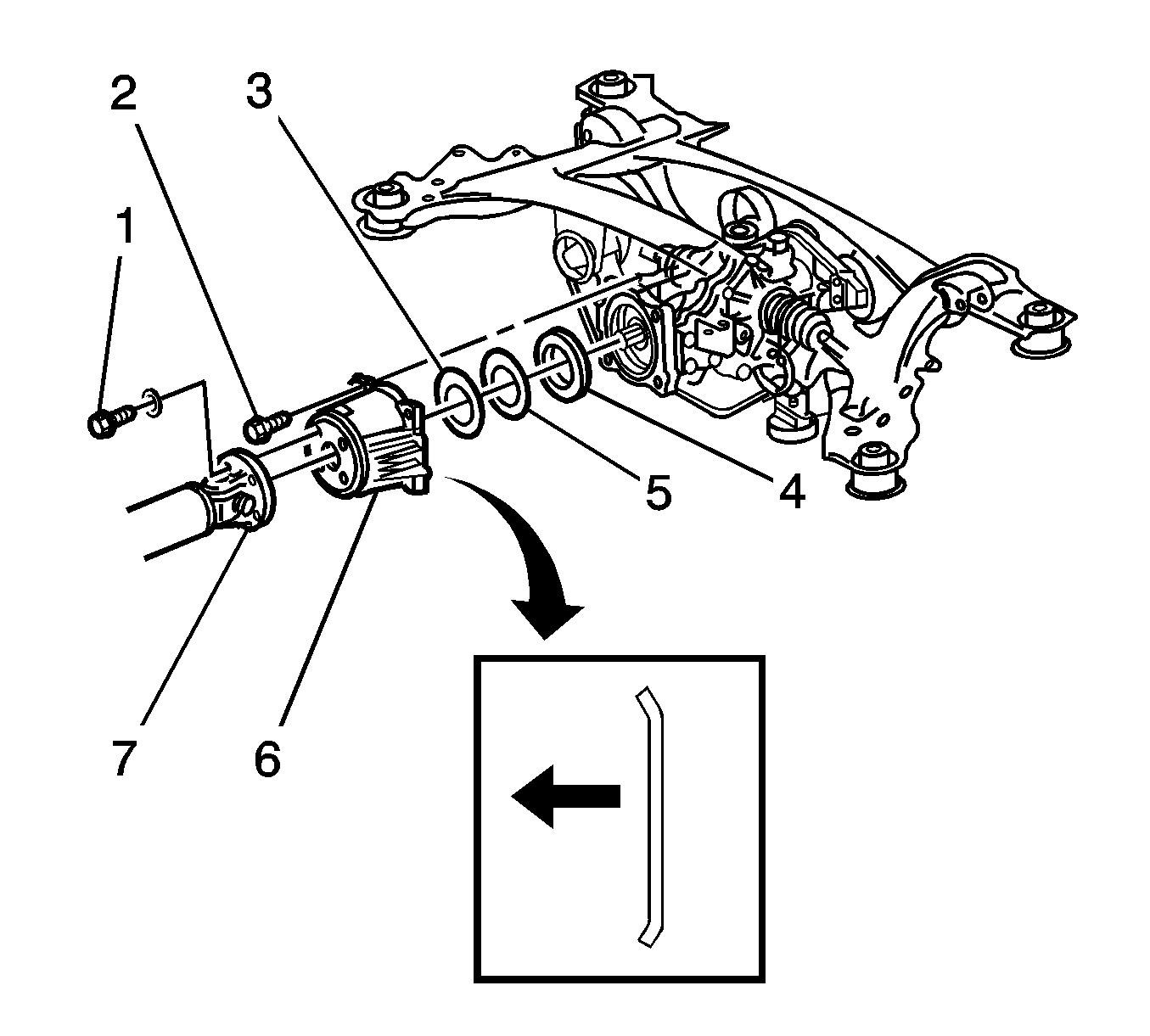
- Remove the 4 bolts retaining the coupling cover (2) to the rear differential.
- Remove the coupling cover (6).
- Remove the coupling washer (3).
- Remove the coupling spacer (5).
- If required, remove the differential carrier front seal (4).
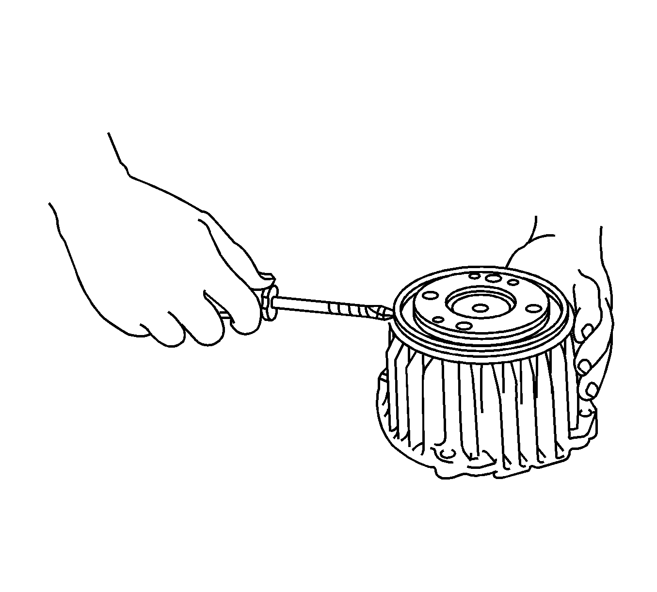
- Using a screw driver remove the dust deflector.
- Remove the viscous coupling.
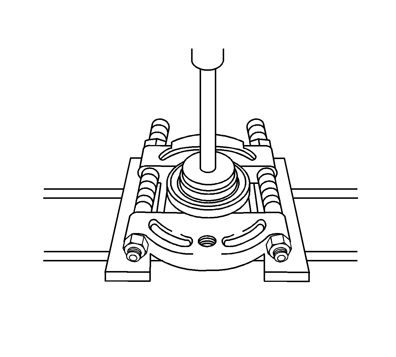
- Remove the front coupling bearing using a press andJ 22912-B
- Remove the rear coupling bearing using a press and J 22912-B
Important: The coupling is not serviceable and must be replaced as an assembly.
Installation Procedures
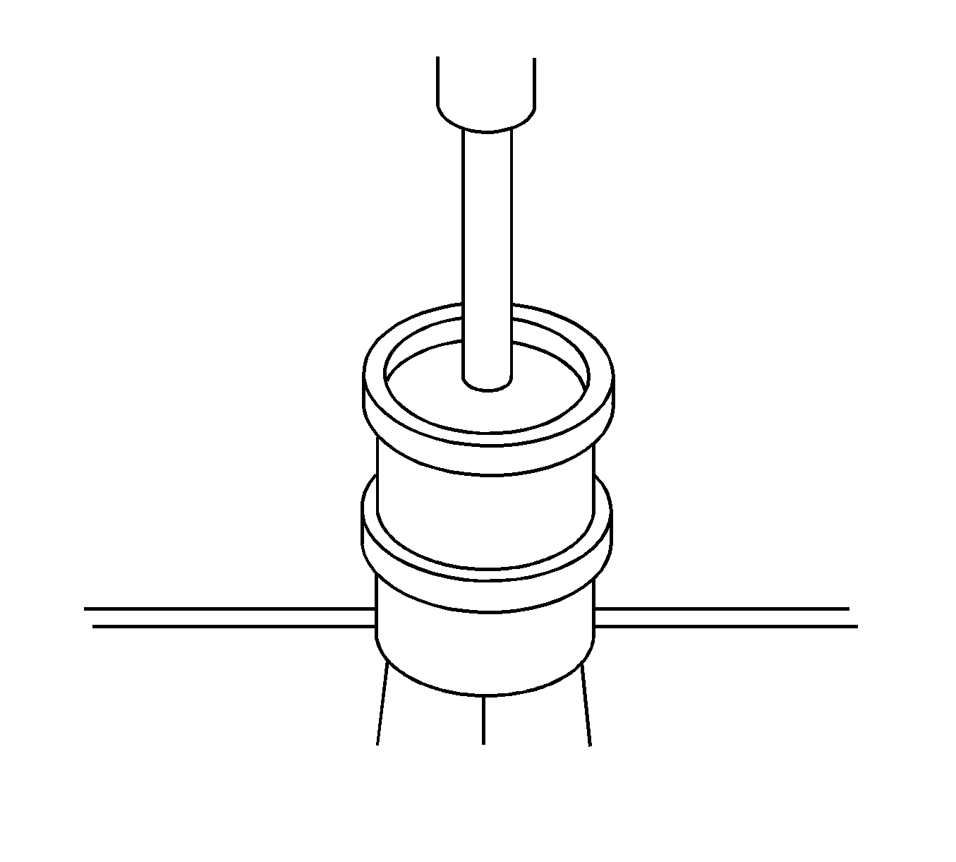
- Install the front coupling bearing using a press.
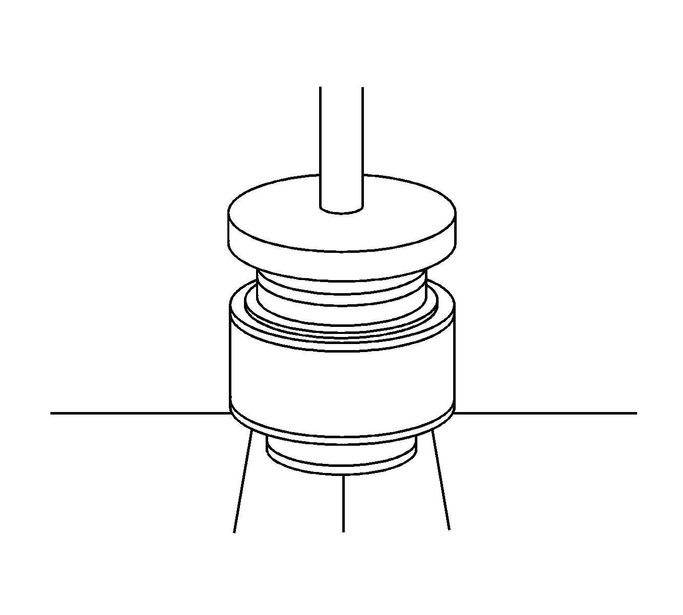
- Install the rear bearing using a press.
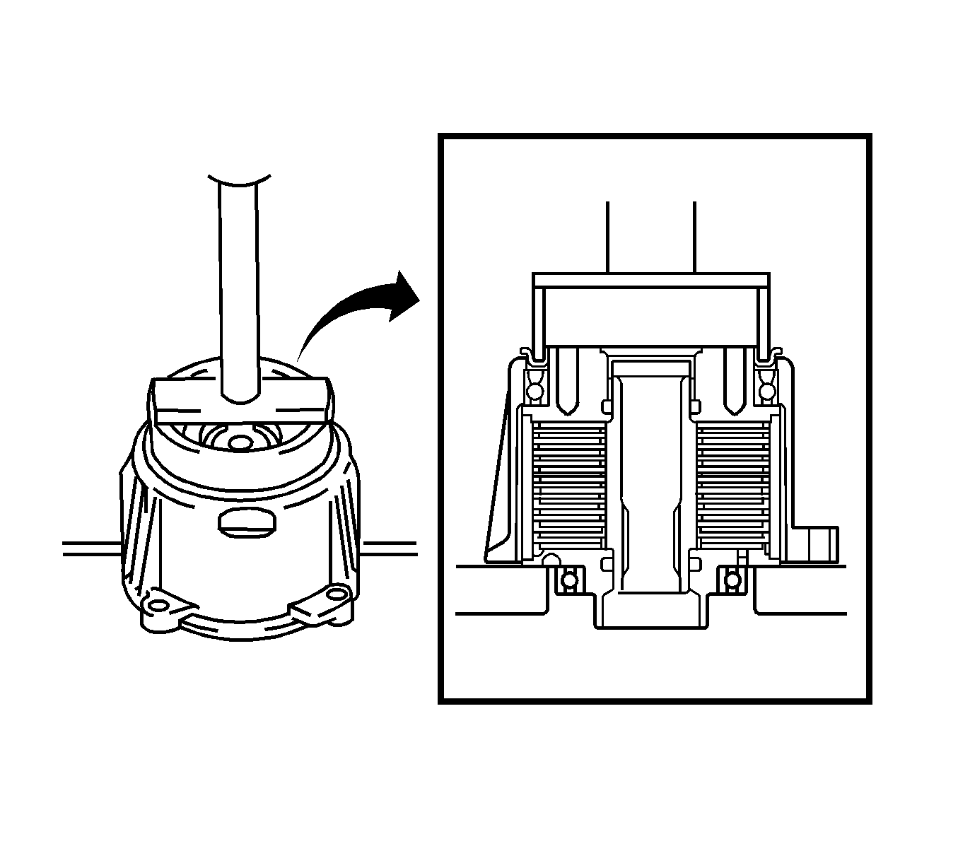
- Install the dust cover using a press.
- If removed, install the front differential carrier seal (4).
- Install the coupling spacer (5).
- Install the coupling washer (3).
- Install the coupling cover on the differential (6).
- Install the coupling cover bolts (2).
- Check the coupling runout using J 8001
- Observe the dial indicator and check the vertical runout. Maximum vertical runout is 0.05 mm (0.002 in).
- Observe he dial indicator and check the horizontal runout. Minimum horizontal runout is 0.05 mm (0.002 in).
- Install the propeller shaft. Refer to Two-Piece Propeller Shaft Replacement in Propeller Shaft.
- Lower the vehicle. Refer to Lifting and Jacking the Vehicle in General Information.

Important: Insure the black seal of the bearing faces the toward the propeller shaft.

Important: Insure the coupling washer concave side is facing the viscous coupling.
Notice: Use the correct fastener in the correct location. Replacement fasteners must be the correct part number for that application. Fasteners requiring replacement or fasteners requiring the use of thread locking compound or sealant are identified in the service procedure. Do not use paints, lubricants, or corrosion inhibitors on fasteners or fastener joint surfaces unless specified. These coatings affect fastener torque and joint clamping force and may damage the fastener. Use the correct tightening sequence and specifications when installing fasteners in order to avoid damage to parts and systems.
Tighten
Tighten the coupling cover bolts to 19 N·m (14 lb
ft).

