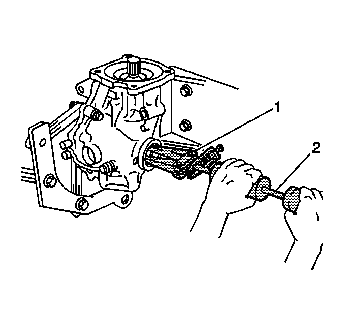
- Install the following components into the differential carrier:
| • | The side gear thrust washers |
| • | The differential side gears |
| • | The pinion gear thrust washers |
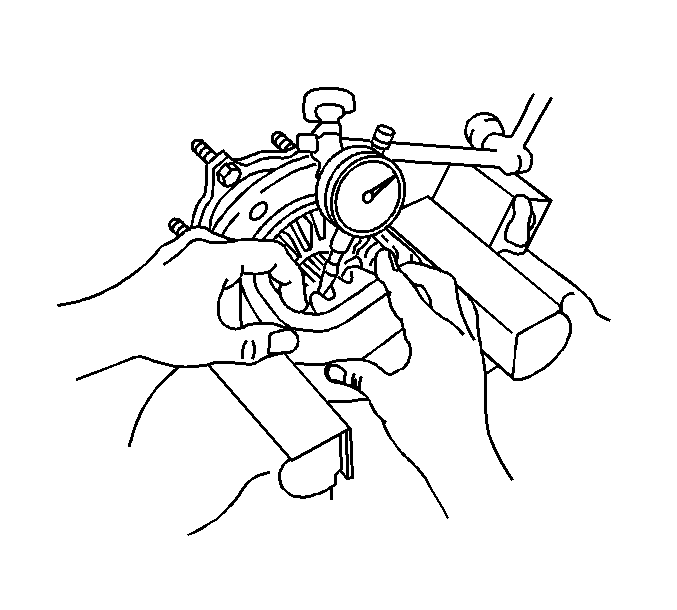
- Use a
J 8001
in order to measure the differential side gear backlash.
| 2.1. | Place the
J 8001
plunger between the teeth of the left side gear . |
| 2.2. | Hold one pinion gear against the differential case, then move the side gear up and down while observing the
J 8001
. |
| 2.3. | The standard differential side gear backlash should be between 0.05-0.20 mm (0.002-0.0079 in). |
| 2.4. | If the differential side gear backlash is not between 0.05-0.20 mm (0.002-0.0079 in), replace the side gear thrust washers with different thicknesses in order to obtain the proper backlash. Refer to
Spacer and Shim Specifications
. |
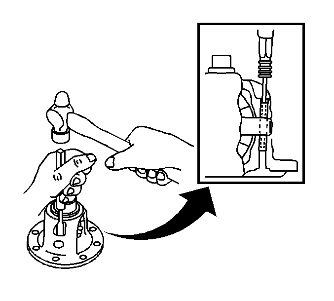
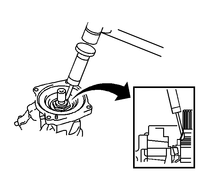
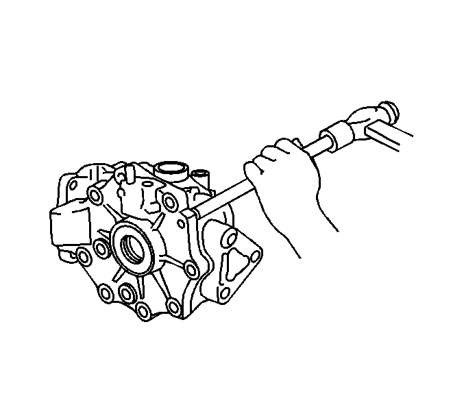
- Use a standard drift punch and hammer in order to install the pinion shaft roll pin into the differential
carrier and the pinion shaft.
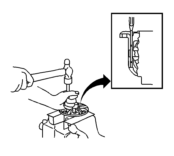
- Stake the outside of the differential case roll pin hole using a hammer and chisel.
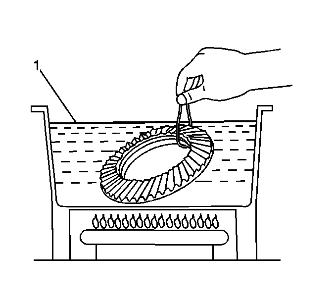
- Heat the ring gear in boiling water (1).
- Clean the contact surfaces of the differential case and the ring gear.
- Carefully remove the ring gear from the boiling water.
- After the moisture as completely evaporated, quickly install the ring gear on the differential case.
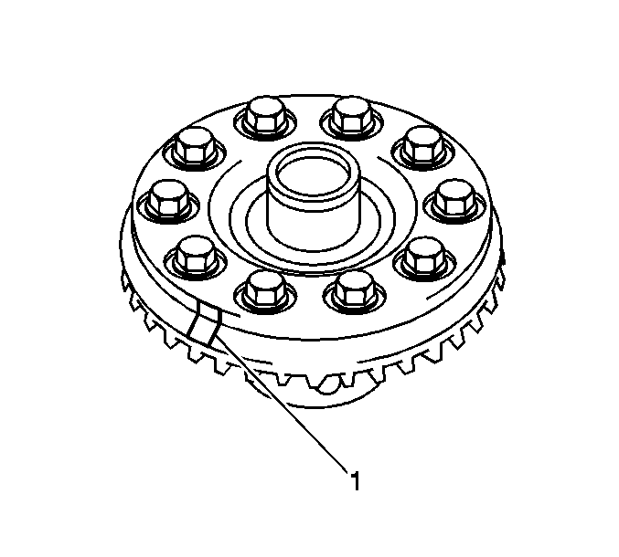
- Align the reference marks (1) on the differential case and the ring gear.
- Temporarily install 10 new bolts.
Notice: Refer to Fastener Notice in the Preface section.
- Allow the ring gear to cool, then tighten the bolts in a star pattern.
Tighten
Tighten the ring gear bolts to 78 N·m (58 lb ft).
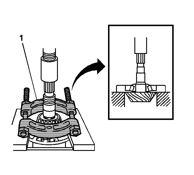
- Install the differential case side bearings using a press.
- Install the drive pinion rear bearing shim that was removed in disassembly.
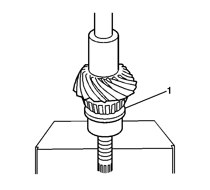
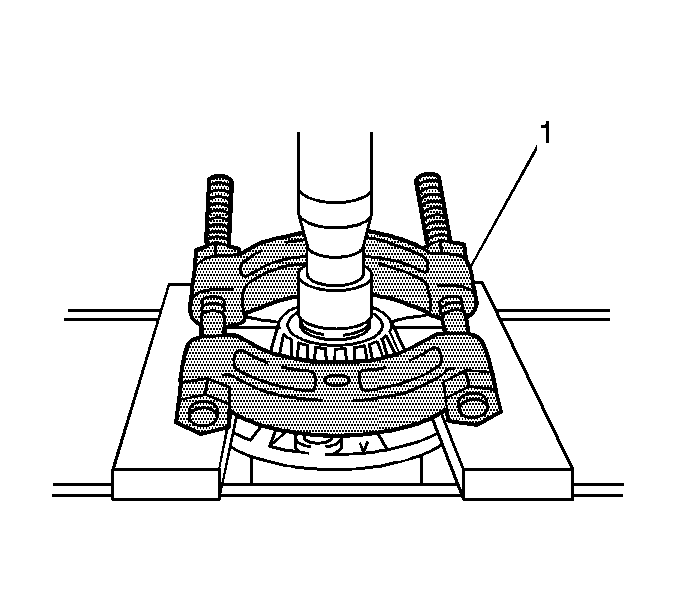
- Install the drive pinion rear bearing (1) using a press.
- Temporarily install the drive pinion and front bearing.
- Lightly coat the drive pinion threads with multi-purpose grease.
- Temporarily adjust the drive pinion preload by tightening the pinion nut.
Tighten
Tighten the pinion nut to no more than 223 N·m (164 lb ft).
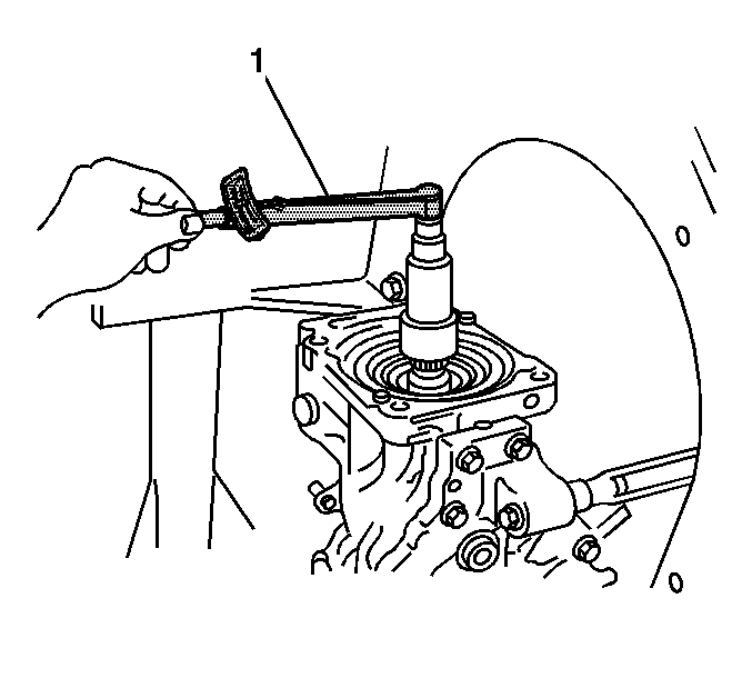
- Measure and record the pinion preload using a torque wrench (1) and
J 46004
.
| • | Starting drive pinion preload with a new set of bearings should be 0.69-1.27 N·m (6-11 lb in). |
| • | Starting drive pinion preload with a reused set of bearings should be 0.39-0.69 N·m (3-6 lb in). |
- Temporarily install the differential case into the differential carrier.
- Temporarily install the differential side cover.
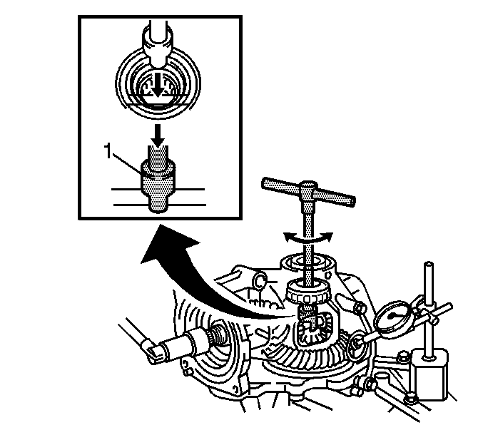
- Measure the ring gear backlash using the
J 8001
and
J 35405
.
- Ring gear backlash should be between 0.10-0.15 mm (0.0039-0.059 in).
Important: If the backlash measurement is not within the specifications given, increase or decrease the thickness of the shims on both sides in equal amounts. Refer to
Spacer and Shim Specifications
.
| • | When the backlash measurement is smaller than the specified value, select a thicker shim for the right side and a thinner shim for the left side. |
| • | When the backlash measurement is larger than the specified value, select a thinner shim for the right side and a thicker shim for the left side. |

- Measure the differential total preload. This measurement should be the drive pinion preload recorded in the previous step plus 0.3-0.5 N·m
(2.6-4.3 lb in).
Adjust total preload by changing the right-hand shim thickness.
- Remove the 10 differential side cover bolts.
- Remove the differential side cover from the differential carrier.
- Remove the differential case from the differential carrier.
- Coat the ring gear teeth with Gear Marking Compound GM P/N 1052351 (Canadian P/N 10953497).
- Temporarily install the differential case in the differential carrier.
- Temporarily install the differential side cover to the differential carrier.
- Install the 10 differential side cover bolts.
- Rotate the drive pinion several times.
- Remove the 10 bolts and the differential side cover.
- Check the ring gear tooth contact pattern.
Important: When changing the thickness of the side gear shim, adjust the drive pinion preload, ring gear backlash and total preload before adjusting the ring gear tooth contact pattern.
- Adjust the contact pattern as necessary.
- Remove the differential case from the differential carrier.
- Remove the drive pinion from the differential carrier.
- Install a new bearing spacer and the oil slinger on the drive pinion.
- Install the drive pinion.
- Using
J 46002
and
J 46004
, install the drive pinion nut.
Tighten
Adjust the drive pinion preload by tightening the nut NO MORE THAN 223 N·m (164 lb ft).
- Check the pinion preload using a torque wrench (1) and
J 46004
.
| • | Starting drive pinion preload with a new set of bearings should be 0.69-1.27 N·m (6-11 lb in). |
| • | Starting drive pinion preload with a reused set of bearings should be 0.39-0.69 N·m (3-6 lb in). |
| • | If the preload is greater than specified, replace the collapsible spacer. |
| • | If the preload is less than specified, tighten the drive pinion nut an additional 13 N·m (9 lb ft) of torque at a time until a maximum of 245 N·m (181 lb ft) is reached. |
- Clean the mating surfaces of the differential side cover and the differential carrier.
- Install the differential case in the differential carrier.
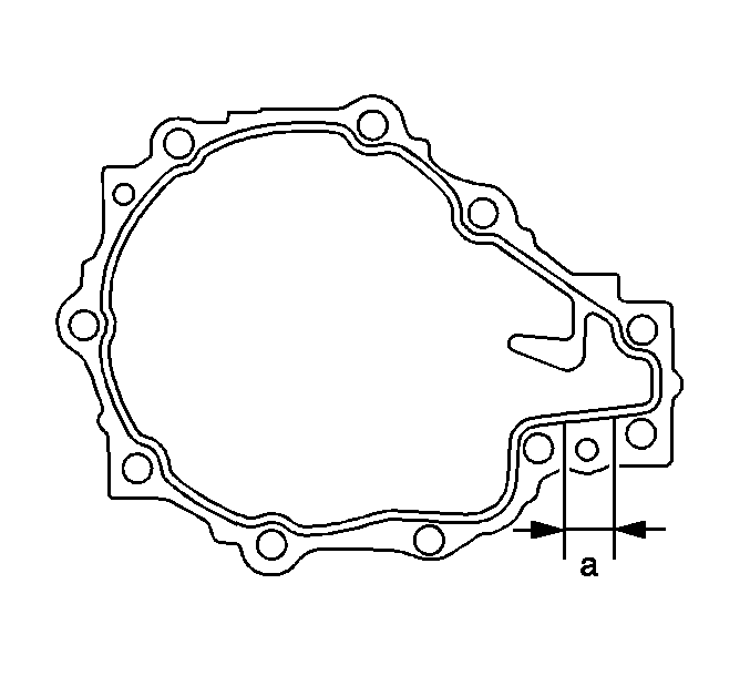
Important: Do not add gear oil or drive the vehicle immediately after cover installation. Allow silicone to cure for 1 hour or more. Avoid rapid acceleration or deceleration for 12 hours or more.
- Apply a 2-3 mm (0.08-0.12 in) bead of Red Silicone Sealant GM P/N 1052366 to the differential side cover. Begin and end the application in area (a).
- Install the differential side cover on the differential carrier.
- Install the 10 side cover bolts.
Tighten
Tighten the 10 bolts to 42 N·m (31 lb ft).
- Check the ring gear backlash, then check the total preload.
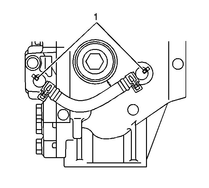
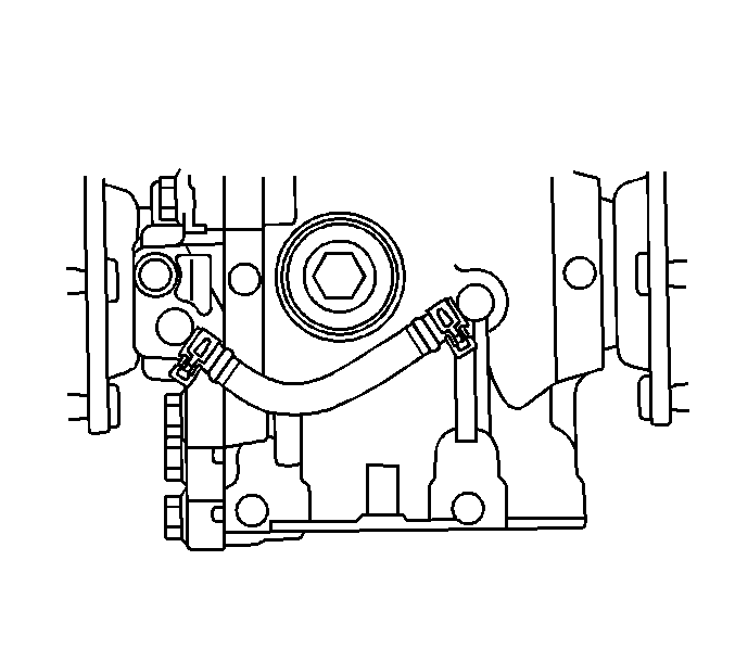
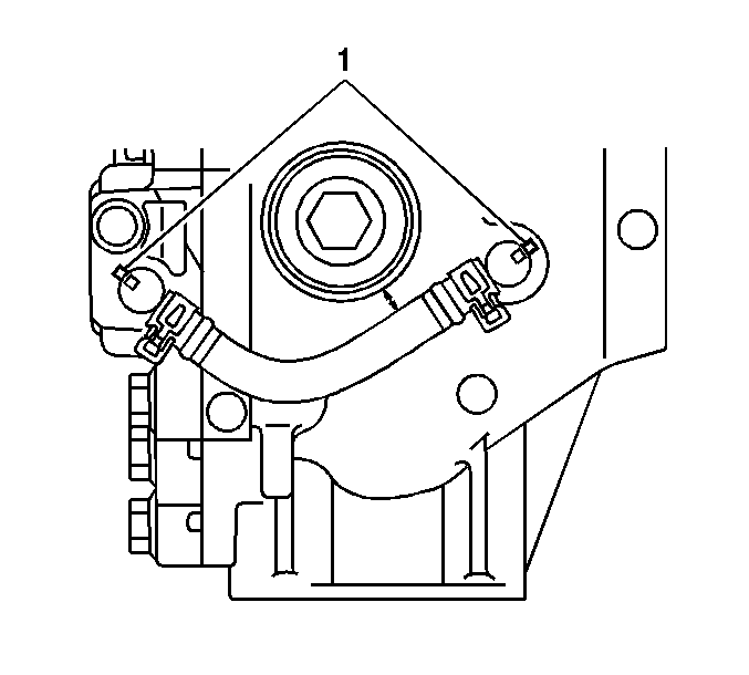
- Align the elbow reference marks, then install elbows into the differential carrier.
- Install the breather hose.
- Install the new front oil seal.
- Install the side gear oil seals.
- Install the coupling into the coupling cover, then install the assembly on the differential carrier.
- Install the 4 coupling cover bolts.
Tighten
Tighten the bolts to 19 N·m (14 lb ft).
- Install the differential carrier into the vehicle. Refer to
Differential Carrier Assembly Replacement
.
- Install the drain plug.
Tighten
Tighten the drain plug to 39 N·m (29 lb ft).
- Fill the differential carrier with 0.5 liters (1.05 pints) of GL-5 80W-90W gear oil or equivalent.
- Install the fill plug.
Tighten
Tighten the fill plug to 39 N·m (29 lb ft).


