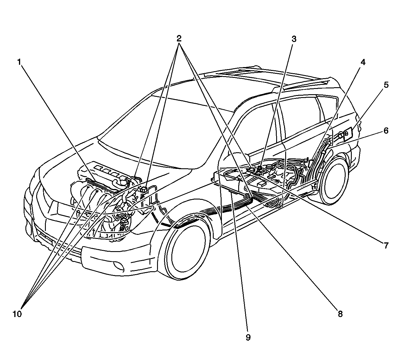
The fuel level sensor is part of the fuel sender assembly. The fuel level sensor (1)
consists of a float (2), a float arm, and a variable resistor (1). The
fuel level is measured by the position of the float in the fuel tank, and is indicated
by a gauge in the instrument panel cluster (IPC) assembly. When the fuel level changes,
the float position changes. The change in the float position increases or decreases
the resistance reading of the variable resistor. The change in the resistance causes
the position of the fuel gauge pointer to change.
The fuel pump is an electric pump that is controlled by the powertrain control
module (PCM) through the circuit opening relay. When the PCM commands the fuel pump
to operate, an impeller is driven by an electric motor in the pump assembly, causing
the fuel in the tank to be drawn into the fuel pump inlet port. The fuel is then pumped
under pressure through the fuel filter and the fuel pressure regulator, out to the
fuel feed pipe and hoses to the fuel rail and the fuel injectors. The fuel pressure
is maintained when the fuel pump is not running by a pressure control valve located
within the pump.
The fuel pump strainer attaches to the lower end of the fuel pump and reservoir
assembly. The fuel pump strainer is made of woven plastic. The functions of the fuel
pump strainer are to filter contaminants and to wick fuel. The fuel pump strainer
is self-cleaning and normally requires no maintenance. Fuel stoppage at this point
indicates that the fuel tank contains an abnormal amount of sediment or water. Clean
the fuel tank and replace a plugged fuel pump strainer with a new strainer.
The fuel filter located in the fuel tank and is part of the fuel sender assembly.
The fuel filter housing is constructed to withstand the maximum fuel system pressure,
exposure to fuel additives, and changes in temperature. The filter element is made
of paper and is designed to trap the particles in the fuel that may cause damage to
the fuel injection system.
The fuel pressure regulator is located in the fuel tank and is part of the fuel
sender assembly. The fuel pressure regulator is a diaphragm-operated pressure relief
valve consisting of a diaphragm, a spring, and a valve. The fuel pressure regulator (2)
is inserted into the fuel sender assembly and sealed with an o-ring (1). The
fuel pressure regulator keeps the fuel delivered to the fuel injectors at the correct
pressure.
Quick connect style fuel fittings provide a simplified means of installing and
connecting the fuel system components. Depending on the vehicle model, there are 2
types of quick connect fittings. Different types of fittings are used at different
locations in the fuel system. Each type of quick connect fitting consists of a unique
female connector and a compatible male fuel pipe end. O-rings located inside of the
female connector provide a leak proof seal. Integral locking tabs or fingers hold
the quick connect fittings together. A special tool is used to service the quick connect
fittings.
The fuel feed and return pipes and hoses carry the fuel from the fuel tank to
the fuel injectors. These pipes and hoses are attached to the underbody of the vehicle
and should be inspected periodically for kinks or dents that could restrict the fuel
flow.
The fuel vapor pipe and hoses carry the fuel vapors from the fuel tank to the
evaporative emission (EVAP) canister located at the rear of the vehicle, ahead of
the fuel tank. The fuel vapors are stored in the canister when the engine is not running.
When the engine is running at the normal operating temperature and the accelerator
pedal is depressed, the PCM will command the EVAP canister purge valve to open and
allow the stored fuel vapors to be purged into the intake manifold where the vapors
will be burned in the combustion process.
The on-board refueling vapor recovery (ORVR) system is an on-board vehicle system
designed to recover fuel vapors during the vehicle refueling operation. Instead of
allowing fuel vapors to escape to the atmosphere the ORVR system transports the vapor
to the EVAP canister for use by the engine. The flow of liquid fuel down the fuel
filler neck provides a liquid seal that prevents fuel vapor from leaving the fuel
system. The ORVR system architecture varies from platform to platform. Some of the
items listed below are optional depending on the platform application. The following
is a list of all the ORVR system components with a brief description of their operation:

