For 1990-2009 cars only
Tools Required
| • | J 37968 Valve Guide Seal Installer Kit |
| • | J 37971 Reamer |
Valve Grinding and Valve Guide Inspection and Replacement
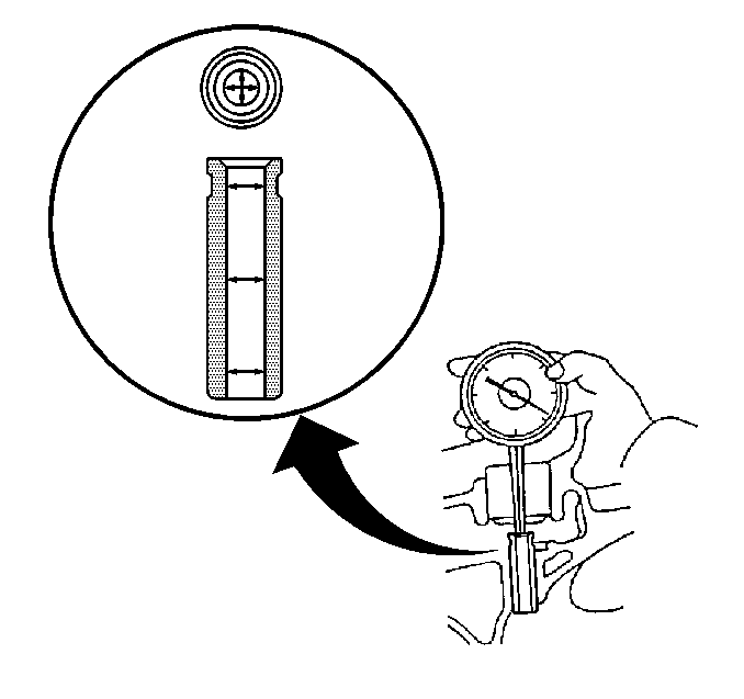
- Use a dial hole gage and measure the inside diameter of the valve guide bushing. Refer to Engine Mechanical Specifications .
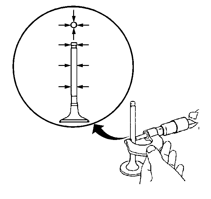
- Use a micrometer and measure the outside diameter of the valve stem. Refer to Engine Mechanical Specifications .
- To obtain the valve guide bushing oil clearance, subtract the valve stem outside diameter measurement from the valve guide bushing inside diameter measurement. Refer to Engine Mechanical Specifications .
- If the clearance is greater than the maximum specified, replace the valve and the valve guide bushing.
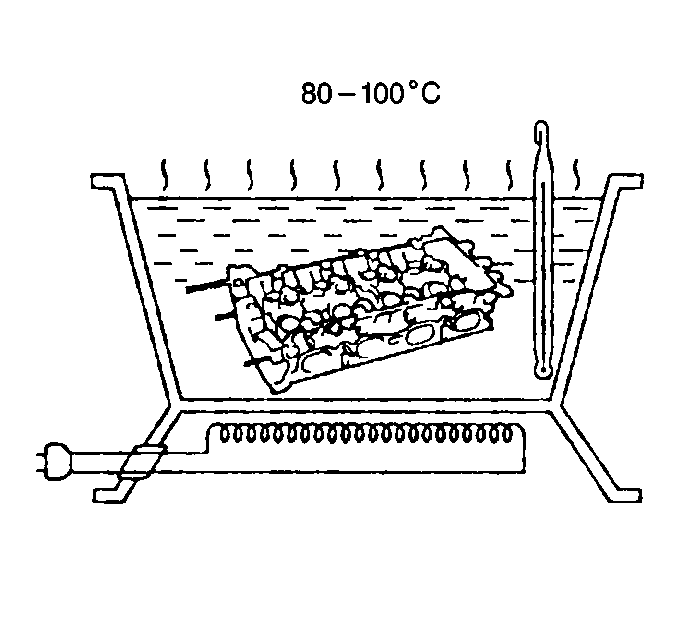
- Gradually heat the cylinder head to 80-100°C (176-212°F)
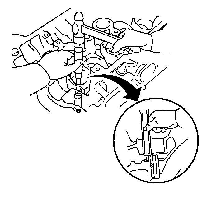
- Use a J 37968 and a hammer and tap out the valve guide bushing.
- Use a dial hole gage and measure the bushing bore diameter of the cylinder head.
- Select a new valve guide bushing (standard or oversize).
- If the bushing bore diameter of the cylinder head is greater than 10.506 mm (0.4136 in), machine the bushing bore to specifications. Refer to Engine Mechanical Specifications .
- If the bushing bore diameter of the cylinder head is greater than 10.556 mm (0.4156 in), replace the cylinder head.
- Measure the intake and exhaust valve guide bushings. The intake valve guide bushings are shorter than the exhaust valve guide bushings.
- Gradually heat the cylinder head to 80-100°C (176-212°F).
- Use a J 37968 and a hammer and tap the new valve guide bushing into the cylinder head.
- Install the valve guide bushing to the specified protrusion height of 15.3-15.7 mm (0.602-0.618 in).
- Use a J 37971 and ream the valve guide bushing to obtain the standard specified clearance between the valve guide bushing and valve stem. Refer to Engine Mechanical Specifications .
- Use the following as a general guideline when reconditioning the cylinder head.


Important: Pay close attention when replacing the valve guide bushings and ensure that the proper valve guide bushing is used.

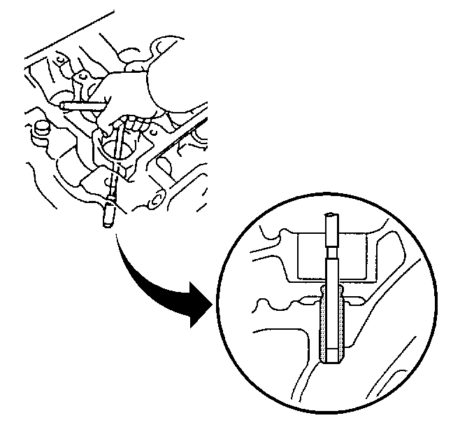
Important: Proper reconditioning of the valve seats is very important. Because the valve guide serves to support and center the valve grinder, it is essential that the valve guide is cleaned properly. If the valve guide requires reaming, this must be done first.
| • | Recondition the valve seat after reaming the valve guide bores. |
| • | Inspect the valve seats for excessive wear and burned spots. Valve seats may be reconditioned by grinding. Using a 45 degree carbide cutter, resurface the valve seat. Remove only enough metal to clean the seat. |
| • | Measure the residuary width of the valve seat. Refer to Engine Mechanical Specifications . |
| • | Replace the cylinder head if the residuary width is less than minimum. |
| • | The valves must seat perfectly for the engine to deliver optimum power and performance. |
| • | Cooling the valve heads is another important factor. Good contact between each valve and its seat in the cylinder head is necessary to insure that the heat in the valve head is properly carried away. |
| • | Regardless of what type of equipment is used, it is essential that the valve guide bores are free from carbon or dirt to ensure the proper centering of the pilot in the guide. |
