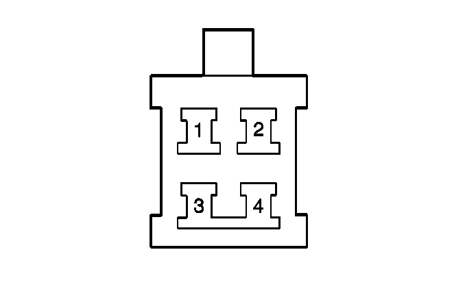
| Table 1: | Overdrive Switch |
| Table 2: | Park/Neutral Position (PNP) Switch |
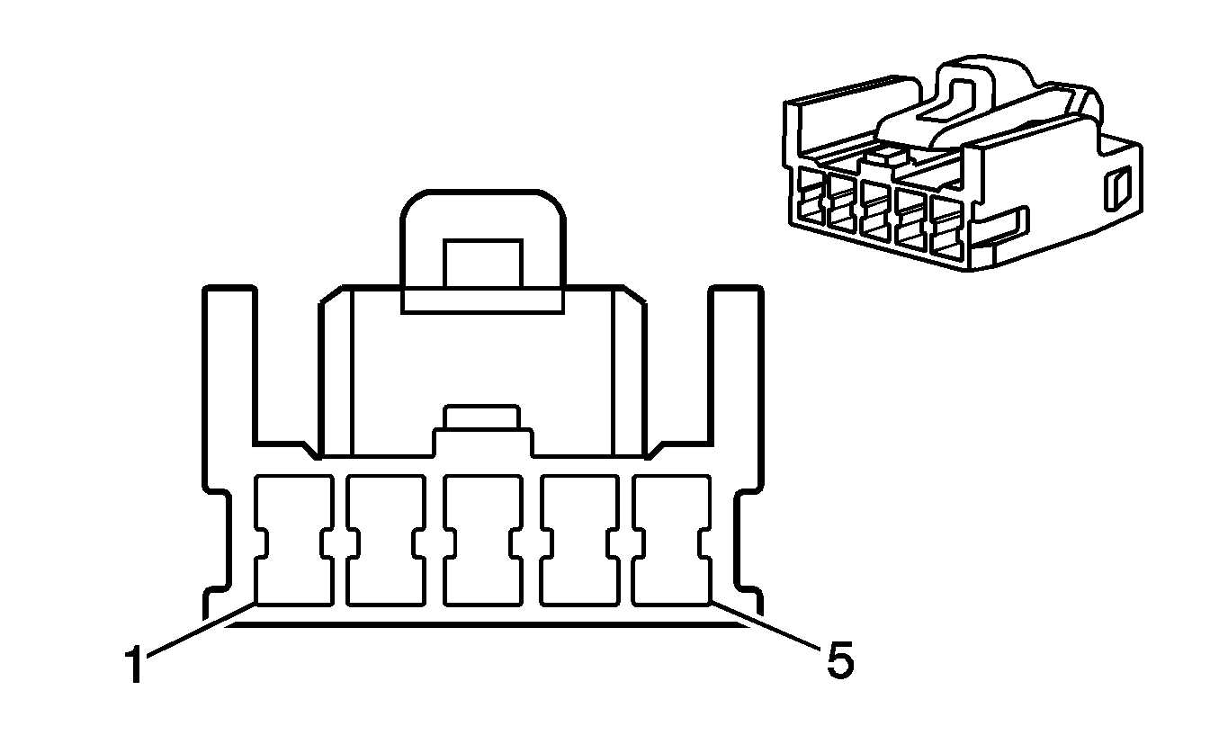
| Table 3: | Shiftlock Control Module |
| Table 4: | Transmission Connector |
| Table 5: | Vehicle Speed Sensor (VSS) |

| ||||||
|---|---|---|---|---|---|---|
Connector Part Information |
| |||||
Pin | Wire Color | Function | ||||
1 | WH/BK | O/D Switch Illumination Ground | ||||
2 | GN/BK | Overdrive Request Circuit | ||||
3 | GN | O/D Switch Illumination Power | ||||
4 | WH/BK | Ground | ||||

| ||||||
|---|---|---|---|---|---|---|
Connector Part Information |
| |||||
Pin | Wire Color | Function | ||||
1 | -- | Not Used | ||||
2 | RD/BK | Reverse Position Signal | ||||
3 | RD/WH | PNP Switch Feed Circuit | ||||
4 | L-GN | 2nd Gear Position Signal | ||||
5 | -- | Not Used | ||||
6 | BK | Start Position Signal | ||||
7 | BU | Drive Position Signal | ||||
8 | L-GN/BK | Low Position Signal | ||||
9 | RD | PNP Start Circuit | ||||

| ||||||
|---|---|---|---|---|---|---|
Connector Part Information |
| |||||
Pin | Wire Color | Function | ||||
1 | WH/BK | Ground | ||||
2 | -- | Not Used | ||||
3 | GN/WH | Stop Lamp Switch Input Circuit | ||||
4 | -- | Not Used | ||||
5 | BK/WH | Shiftlock Control Module Feed Circuit | ||||

| ||||||
|---|---|---|---|---|---|---|
Connector Part Information |
| |||||
Pin | Wire Color | Function | ||||
1 | WH/BU | Transmission Fluid Temperature Input Circuit | ||||
2 | BU/OG | 2nd Brake Control Solenoid | ||||
3 | RD/WH | PC Solenoid High | ||||
4 | BU/WH | TCC Solenoid Control | ||||
5 | RD/YE | Shift Solenoid 1 Control | ||||
6 | BN | Transmission Fluid Temperature Ground Circuit | ||||
7 | -- | Not Used | ||||
8 | PK | PC Solenoid Low | ||||
9 | -- | Not Used | ||||
10 | BU | Shift Solenoid 2 Circuit | ||||

| ||||||
|---|---|---|---|---|---|---|
Connector Part Information |
| |||||
Pin | Wire Color | Function | ||||
1 | BK | Sensor Ground | ||||
2 | WH | VSS Input | ||||
