For 1990-2009 cars only
Special Tools
J-43178 Fuel Line Disconnect Tool
Removal Procedure
- Discharge the fuel system pressure. Refer to Fuel Pressure Relief.
- Disconnect the cable from the negative battery terminal. Refer to Battery Negative Cable Disconnection and Connection
- Remove the engine cover. Refer to Engine Cover Replacement.
- Remove the air cleaner assembly. Refer to Air Cleaner Element Replacement.
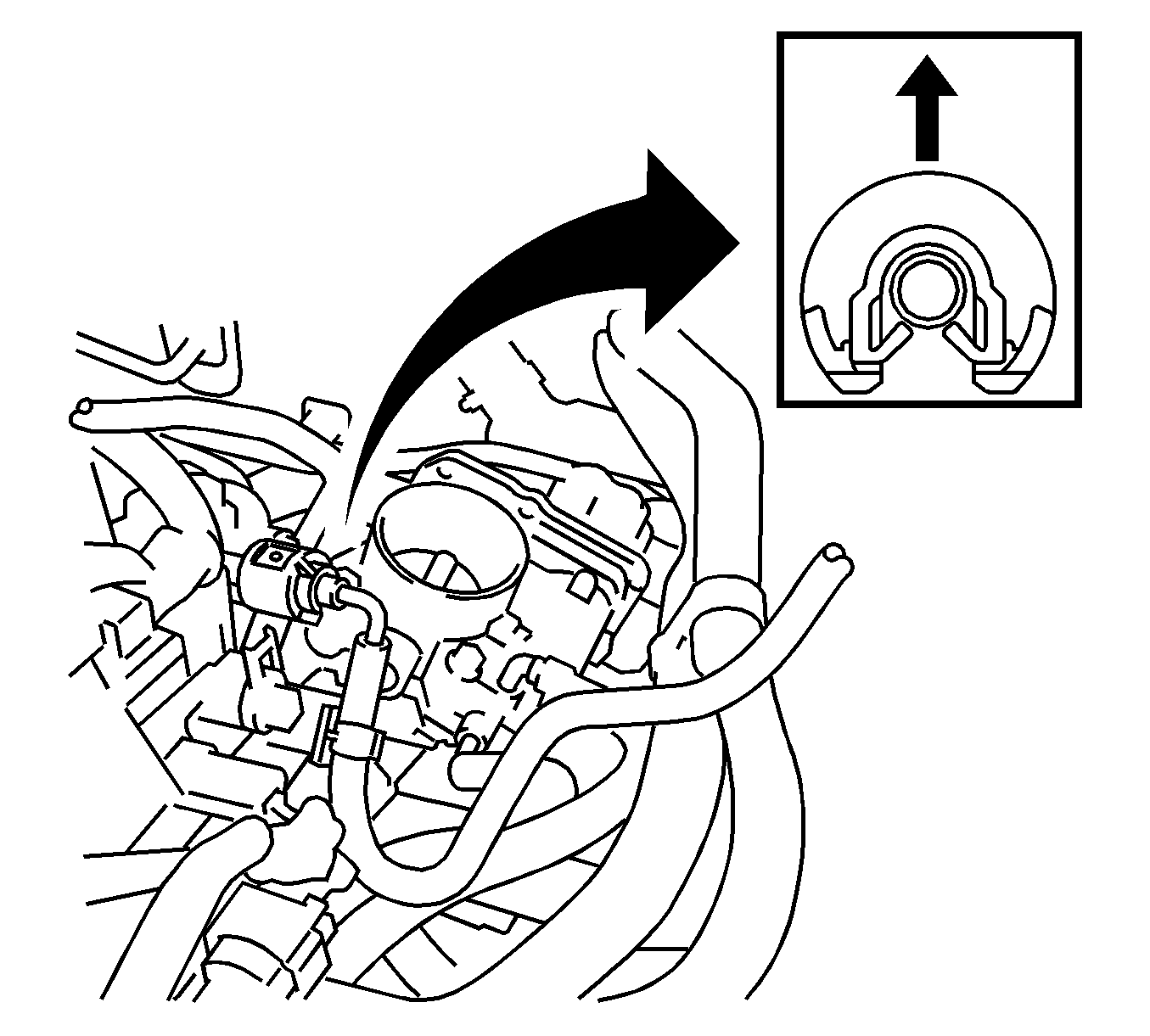
- Remove the fuel tube from the fuel hose clamp.
- Remove the fuel pipe clamp.
- Wipe off any dirt on the fuel tube connector.
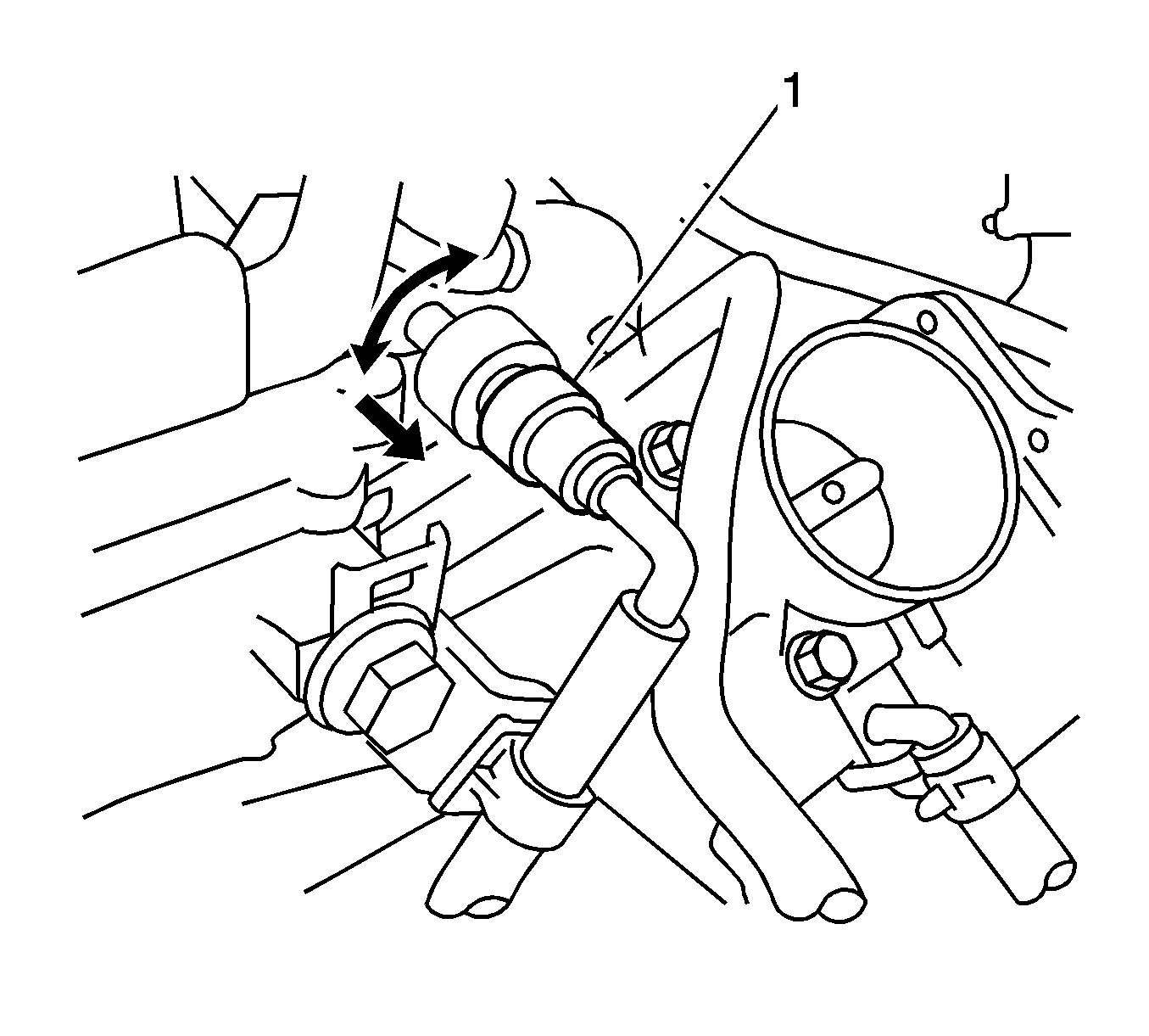
- Hold the fuel tube connector, and then install the J-43178 disconnect tool .
- Turn the J-43178 disconnect tool to align the retainer inside the fuel tube connector with the chamfered part of the J-43178 disconnect tool .
- Insert the J-43178 disconnect tool into the fuel tube and hold it. Then push the fuel tube connector toward the J-43178 disconnect tool .
- Mount the retainer of the fuel tube connector onto the chamfered part of the J-43178 disconnect tool .
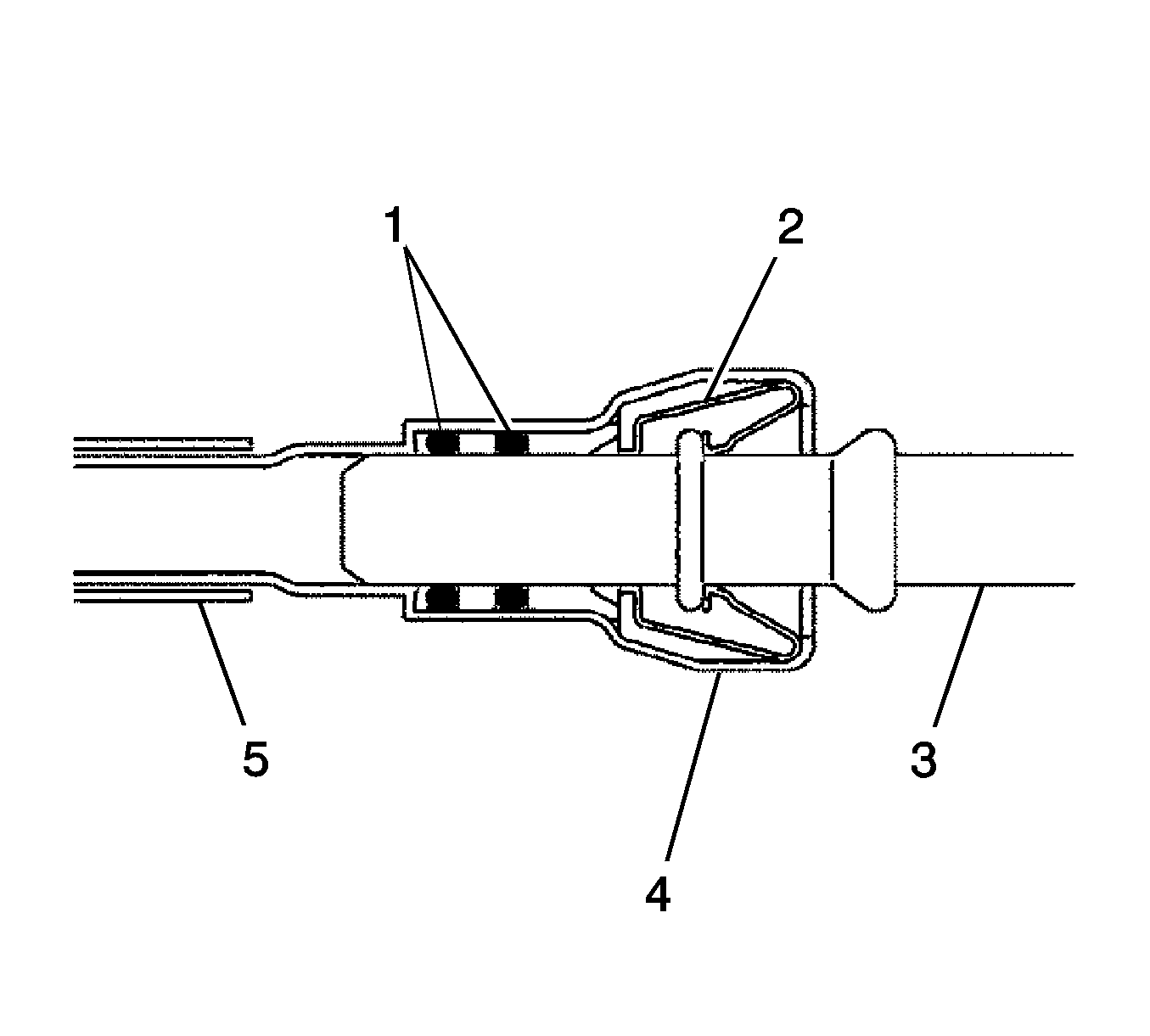
- Slide the J-43178 disconnect tool and fuel tube connector (2) together towards the fuel tube (3) until they make a "click" sound, and then disconnect the fuel tube.
- Drain the fuel remaining inside the fuel tube.
- Cover the fuel tube and fuel pipe with a plastic bag to protect the disconnected part.
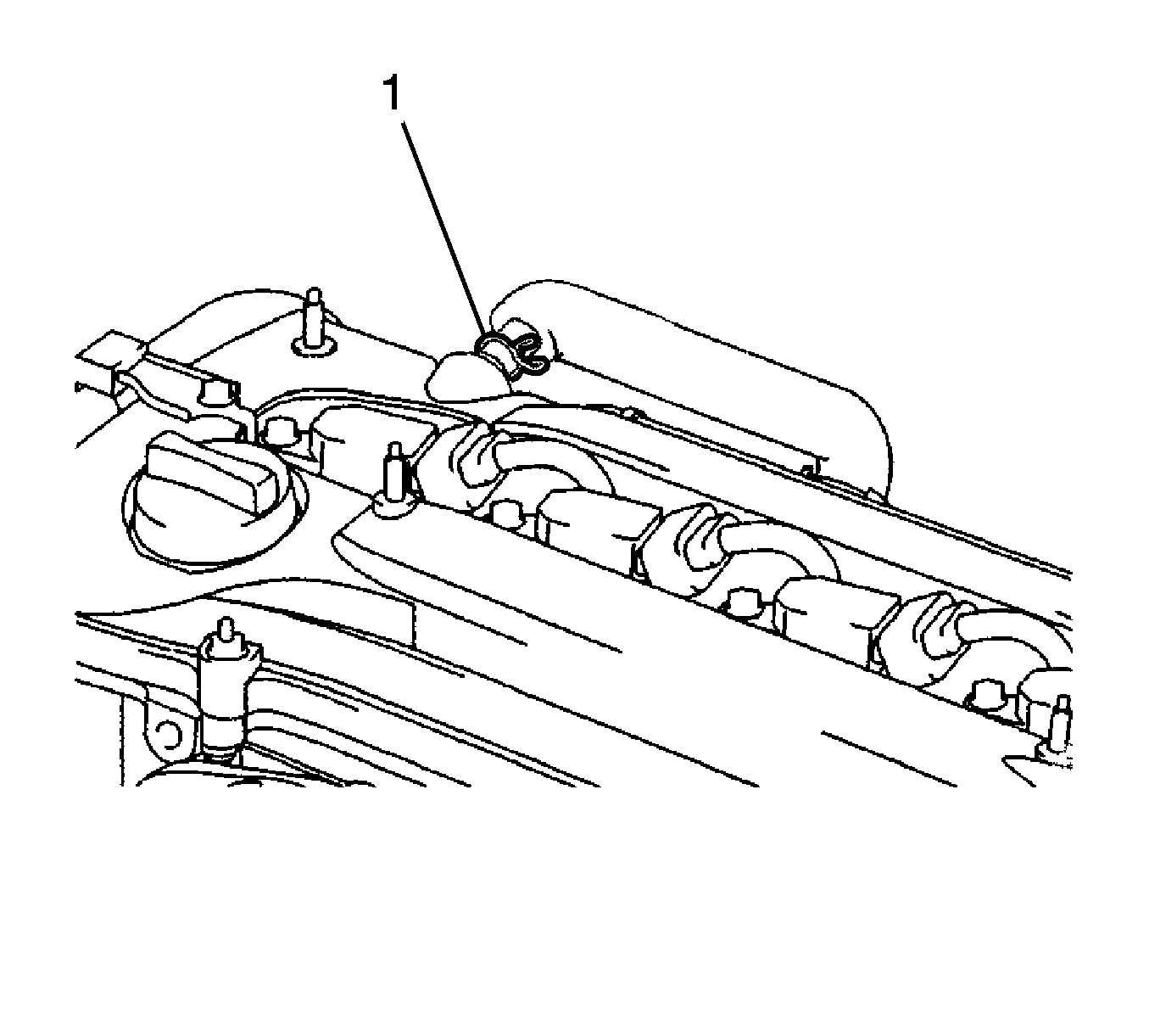
- Disconnect the ventilation hose (1) from the ventilation valve.
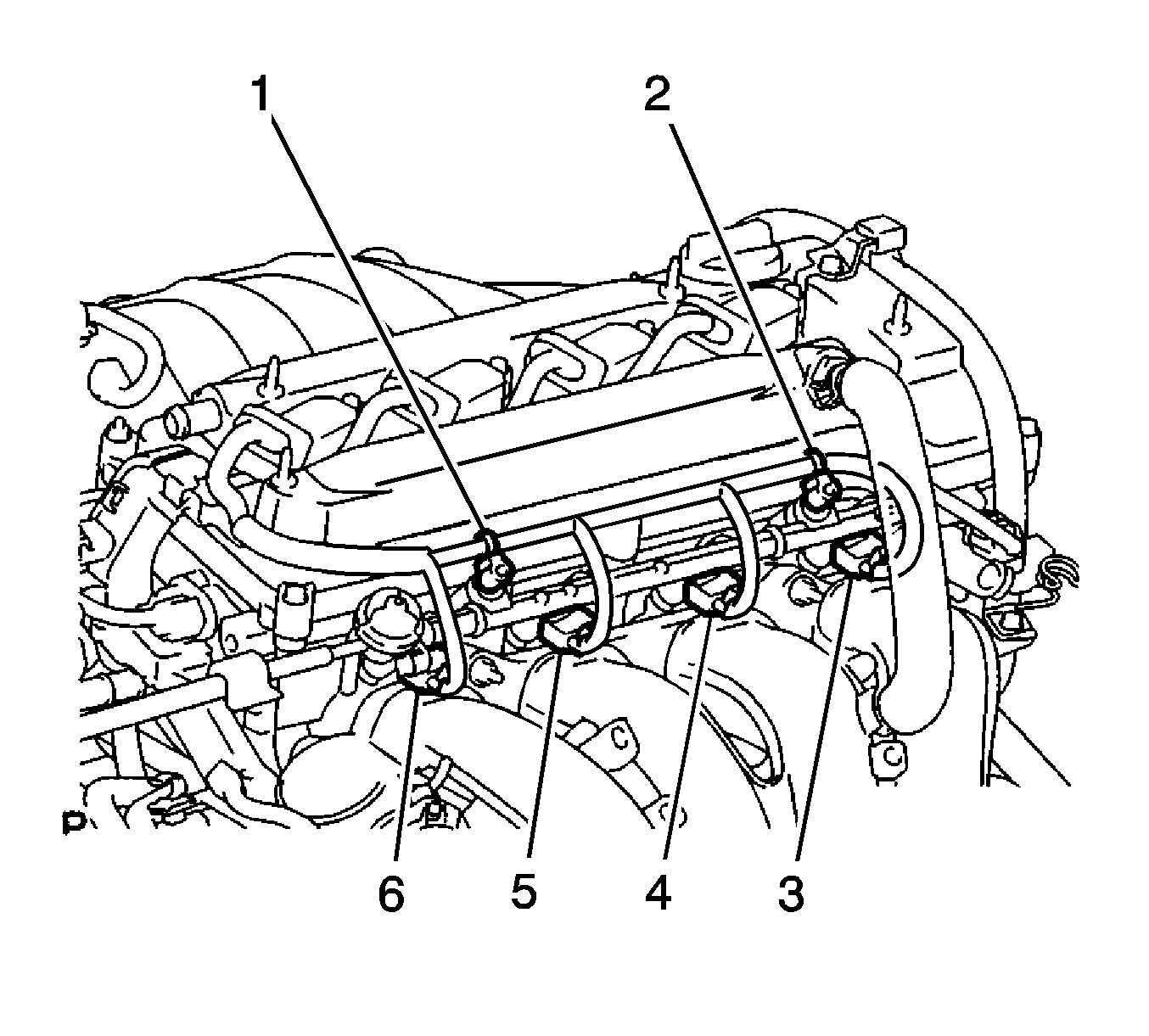
- Remove the 2 wire harness clamps (1, 2).
- Disconnect the 4 fuel injector connectors (3, 4, 5, 6).
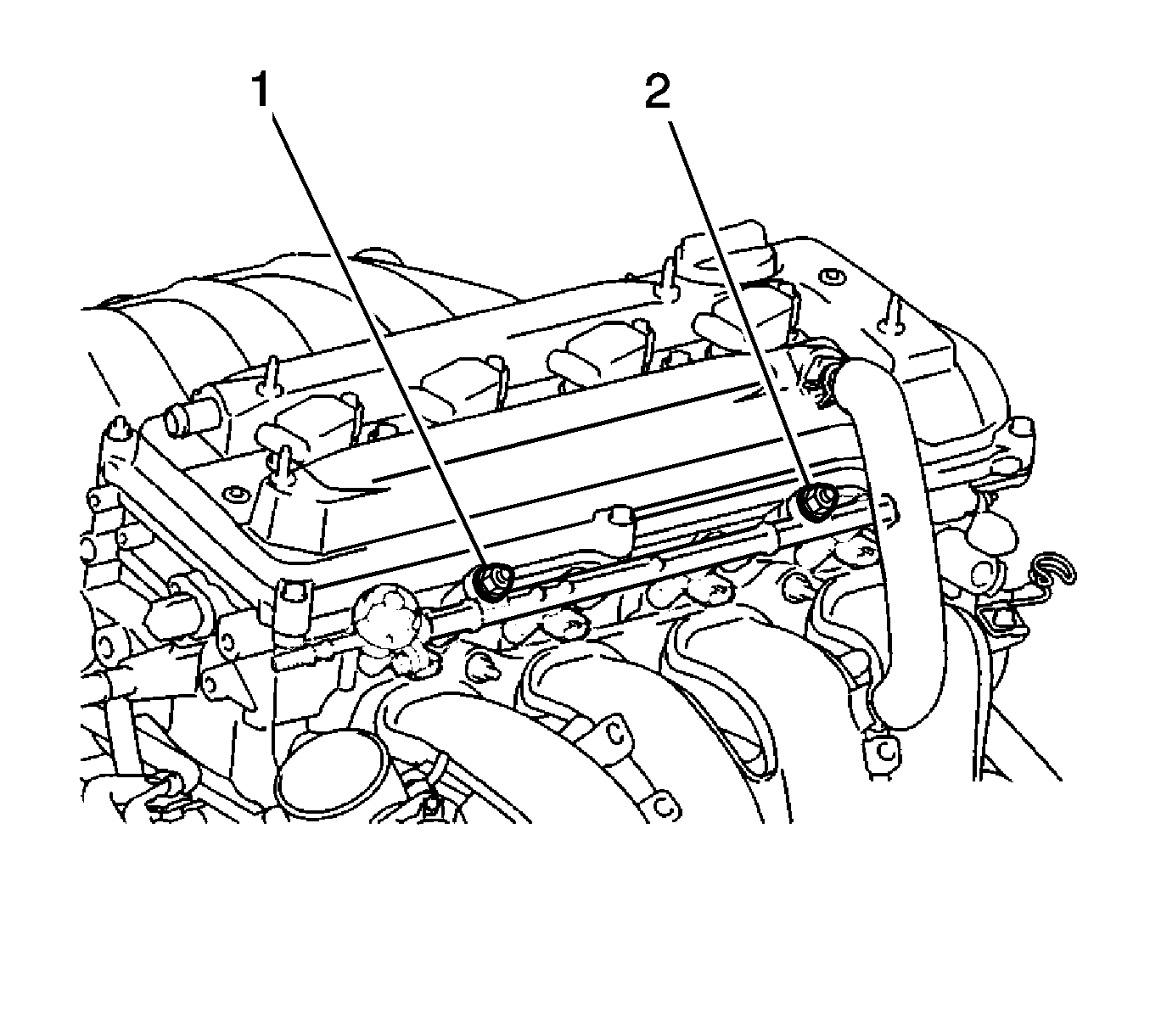
- Remove the 2 bolts (1, 2), then remove the fuel delivery pipe together with the 4 fuel injectors.
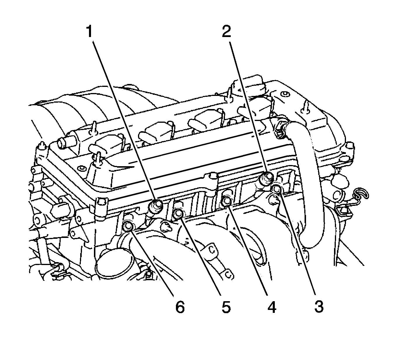
- Remove the 2 delivery pipe spacers (1, 2) from the cylinder head.
- Remove the 4 insulators (3, 4, 5, 6) from the cylinder head.
- Remove fuel injector assembly.
- Pull the 4 fuel injectors out of the fuel delivery pipe.
Warning: Refer to Battery Disconnect Warning in the Preface section.

Installation Procedure
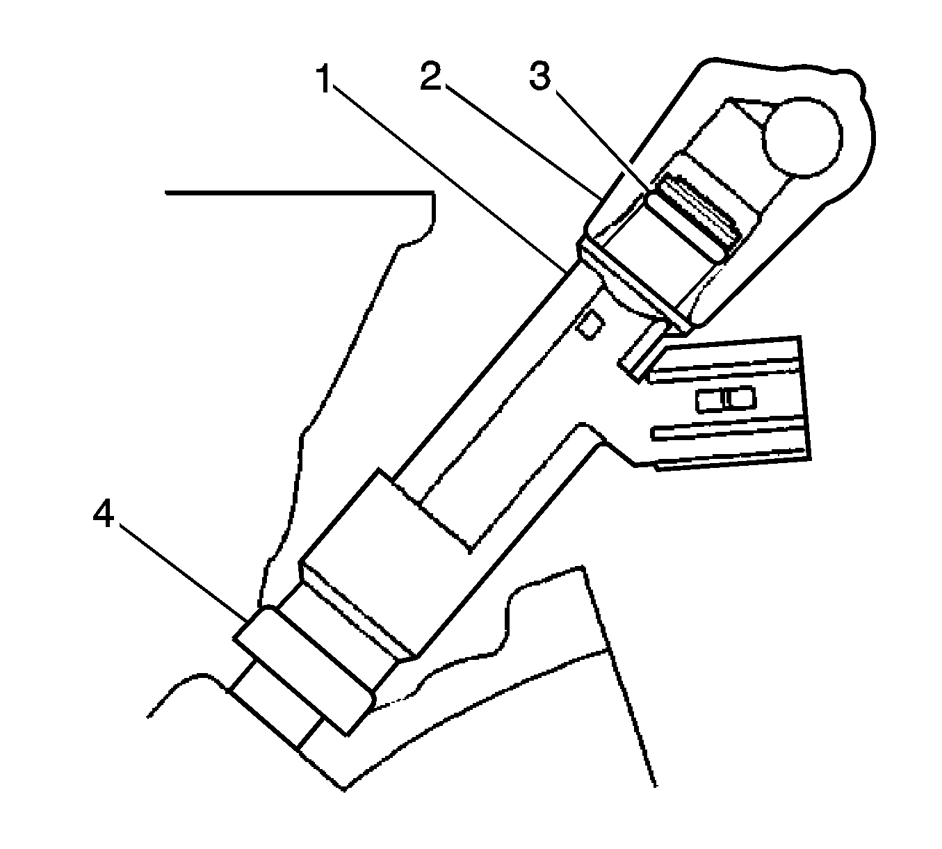
- Apply a light coat of oil to new O-rings (1), then install one onto each fuel injector.
- Apply a light coat of oil to the part of the fuel delivery pipe which comes into contact with the O-ring of the fuel injector.
- Apply a light coat of oil to the O-ring again, then install the right and left fuel injectors onto the fuel delivery pipe.
- Check that the fuel injector rotates smoothly. If the fuel injector does not rotate, replace the O-ring.
- Install 4 new insulators (3, 4, 5, 6) to the cylinder head.
- Install the 2 delivery pipe spacers (1, 2) onto the cylinder head.
- Install the fuel delivery pipe (2) together with the 4 fuel injectors (1), then hand tighten the 2 bolts.
- Check that the fuel injector rotates smoothly. If the fuel injector does not rotate, replace the O-ring (3).
- Install the 2 bolts (1, 2) and tighten to 20 N·m (15 lb ft).
- Connect the 4 fuel injector connectors (3, 4, 5, 6).
- Install the 2 wire harness clamps (1, 2).
- Connect the ventilation hose (1) to the ventilation valve.
- Connect the fuel main tube.
- Push the fuel tube connector until it makes a "click" sound.
- Install the fuel pipe clamp.
- Install the fuel tube to the fuel hose clamp.
- Install the air cleaner assembly. Refer to Air Cleaner Element Replacement.
- Install the engine cover sub-assembly. Refer to Engine Cover Replacement.
- Connect the cable to the negative battery terminal.
- Inspect for a fuel leak.


Caution: Refer to Fastener Caution in the Preface section.


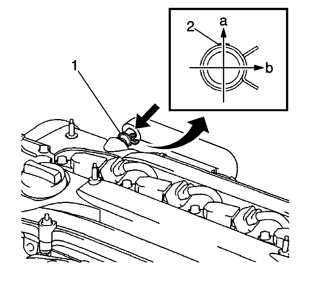
Note: Make sure that the paint mark and hose clamp are at the correct angle when installing the hose.
Warning: Refer to Battery Disconnect Warning in the Preface section.
