For 1990-2009 cars only
Removal Procedure
- Disconnect the cable from the negative battery terminal. Refer to Battery Negative Cable Disconnection and Connection.
- Remove the front floor console assembly. Refer to Front Floor Console Replacement.
- Remove the battery. Refer to Battery Replacement.
- Remove the battery tray. Refer to Battery Tray Replacement.
- Remove the engine cover. Refer to Engine Cover Replacement.
- Remove the air cleaner assembly.
- Remove the center exhaust pipe assembly.
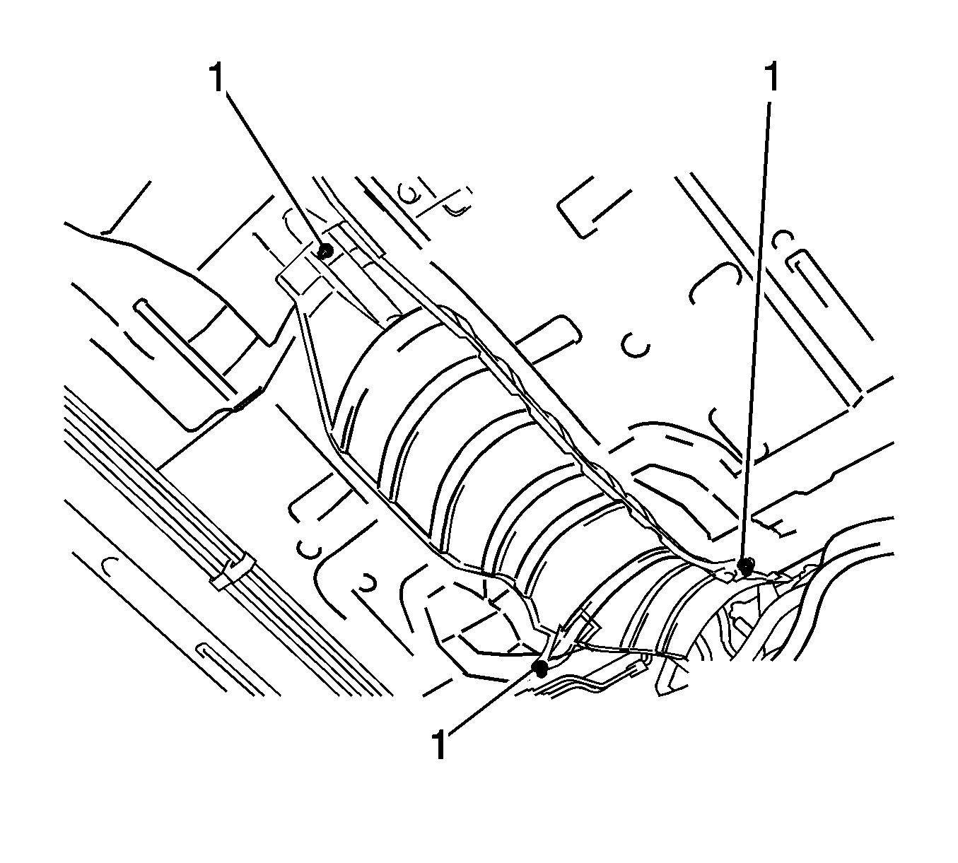
- Remove the nuts (1) and the front No. 1 floor heat insulator.
- Move the shift lever to N.
- Disconnect the end of the transmission control cable assembly (1) from the shift lever assembly.
- Pull out the stopper of the transmission control cable.
- Rotate the nut counterclockwise approximately 180 degrees, while holding the nut in that position, disconnect the transmission control cable from the shift lever retainer.
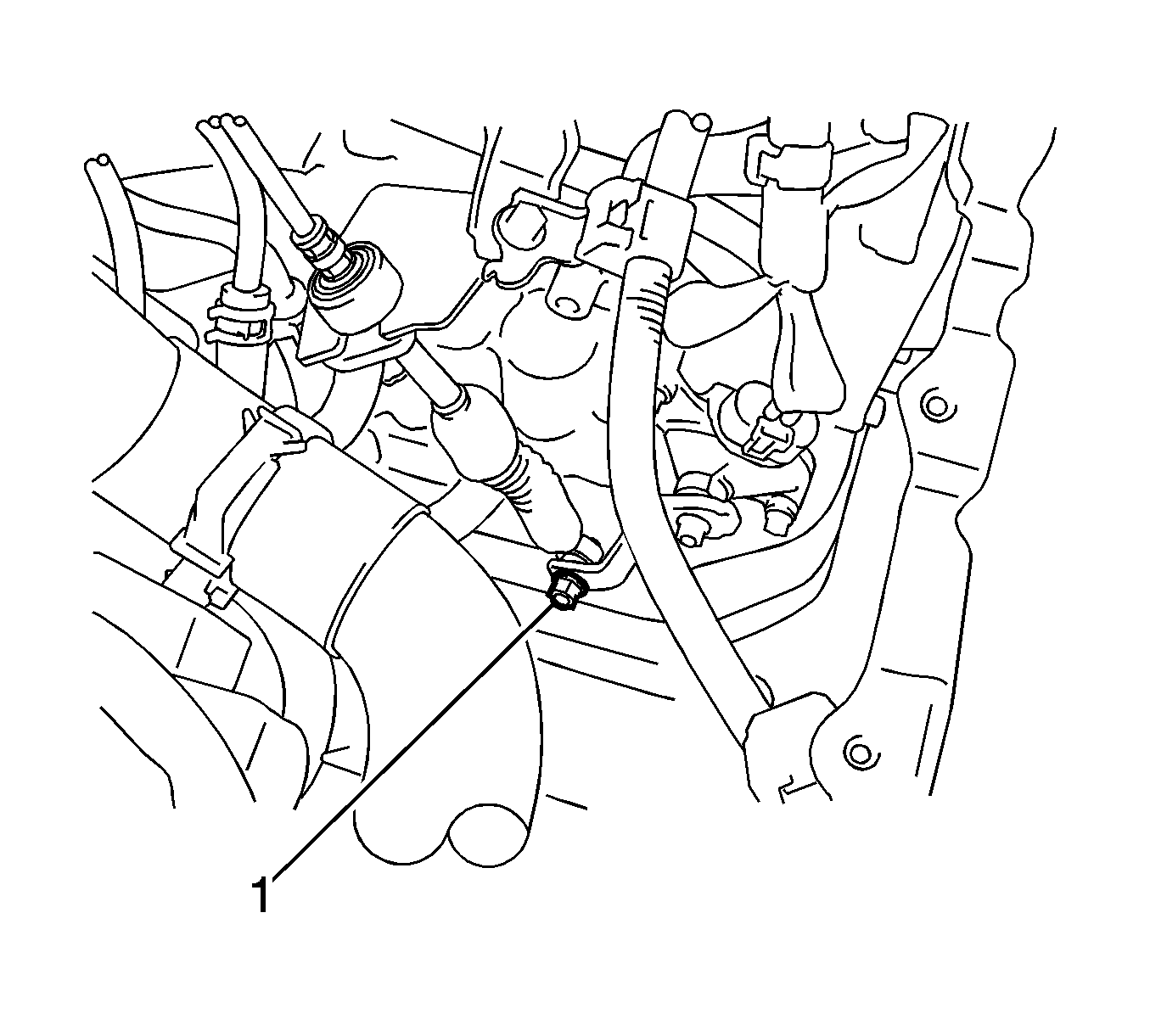
- Remove the nut (1) and disconnect the control cable assembly from the control shaft lever.
- Remove the clip and disconnect the transmission control cable assembly from the control cable bracket.
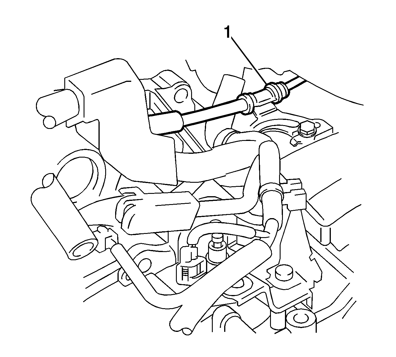
- Disconnect the control cable assembly (1) from the control cable bracket.
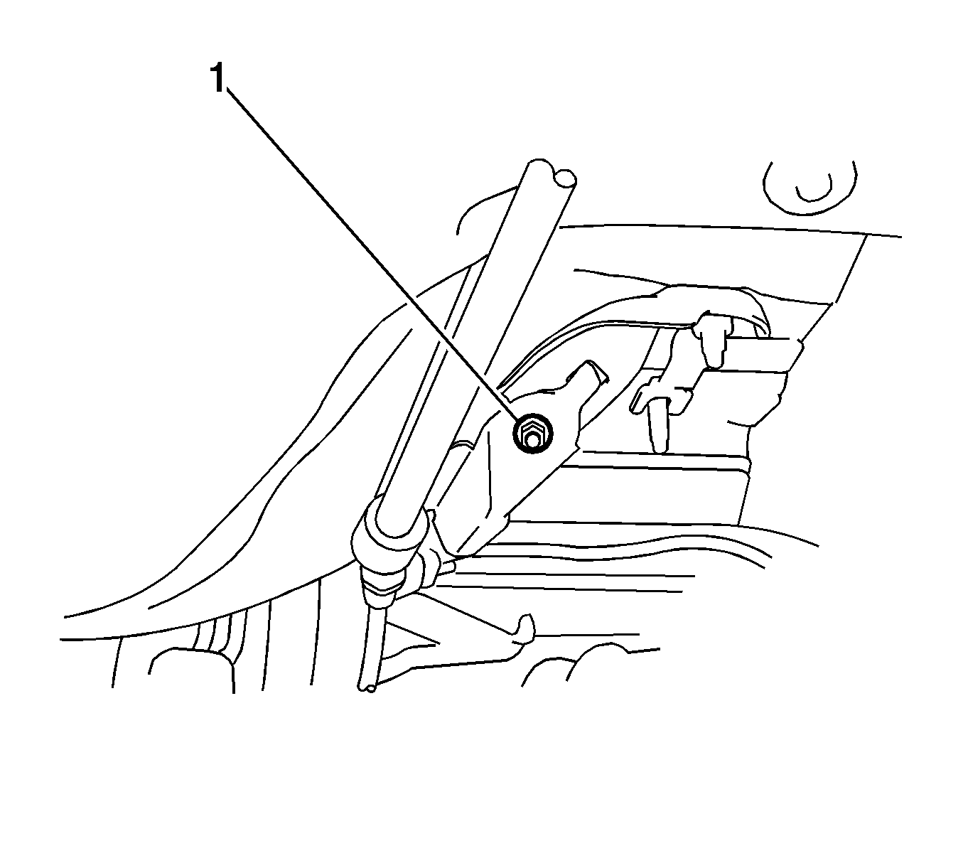
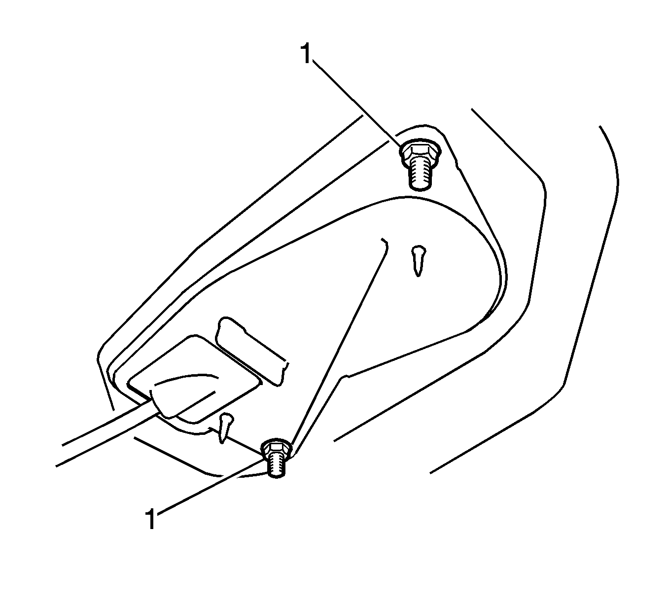
- Remove the nut (1) and separate the transmission control cable support.
- Remove the nuts (1) and separate the transmission control cable assembly.
- Pull out the transmission control cable assembly.


Note: Do not remove the stopper. If the stopper is removed, reinstall it to its original position.
Note: Do not over-rotate the nut as it will come off the internal spring and the transmission control cable will not be reusable.
Installation Procedure
- Put the transmission control cable into the cabin and connect the transmission control cable with the nuts (1). Tighten the nuts to 5 N·m (44 lb in).
- Install the transmission control cable support with the nut (1) and tighten to 5 N·m (44 lb in).
- Connect the transmission control cable (1) to the control cable bracket.
- Connect the transmission control cable to the bracket with a new clip.
- Connect the transmission control cable assembly to the control shaft lever with the nut (1) and tighten to 15 N·m (11 lb ft).
- Turn the nut (2) of the transmission control cable 180 degrees counterclockwise. While holding the nut in place, push in the stopper until the stopper clicks twice.
- Install the outer part of the transmission control cable to the shift lever retainer. Check that the spring is positioned properly and push in the stopper.
- Push the claws (1) together at the top of the transmission control cable lock piece. While holding the claws together, push the lugs on the bottom of the lock piece toward each other and upward to pull out the lock piece.
- Install the cable end all the way to the base of the pin.
- Install the cable end to the shift lever assembly.
- Push the lock piece into the adjuster case (2).
- Install the front No. 1 floor heat insulator with the nuts (1) and tighten to 6 N·m (53 lb in).
- Install the center exhaust pipe assembly.
- Install the air cleaner assembly.
- Install the engine cover. Refer to Engine Cover Replacement.
- Install the battery tray. Refer to Battery Tray Replacement.
- Install the battery. Refer to Battery Replacement.
- Install the front floor console assembly. Refer to Front Floor Console Replacement.
- Connect the cable to the negative battery terminal. Refer to Battery Negative Cable Disconnection and Connection.
- Inspect the shift lever position.
- Adjust the shift lever position.
Caution: Refer to Fastener Caution in the Preface section.

Note: Before installing the transmission control cable assembly, check that the park/neutral position switch and the shift lever are in neutral.


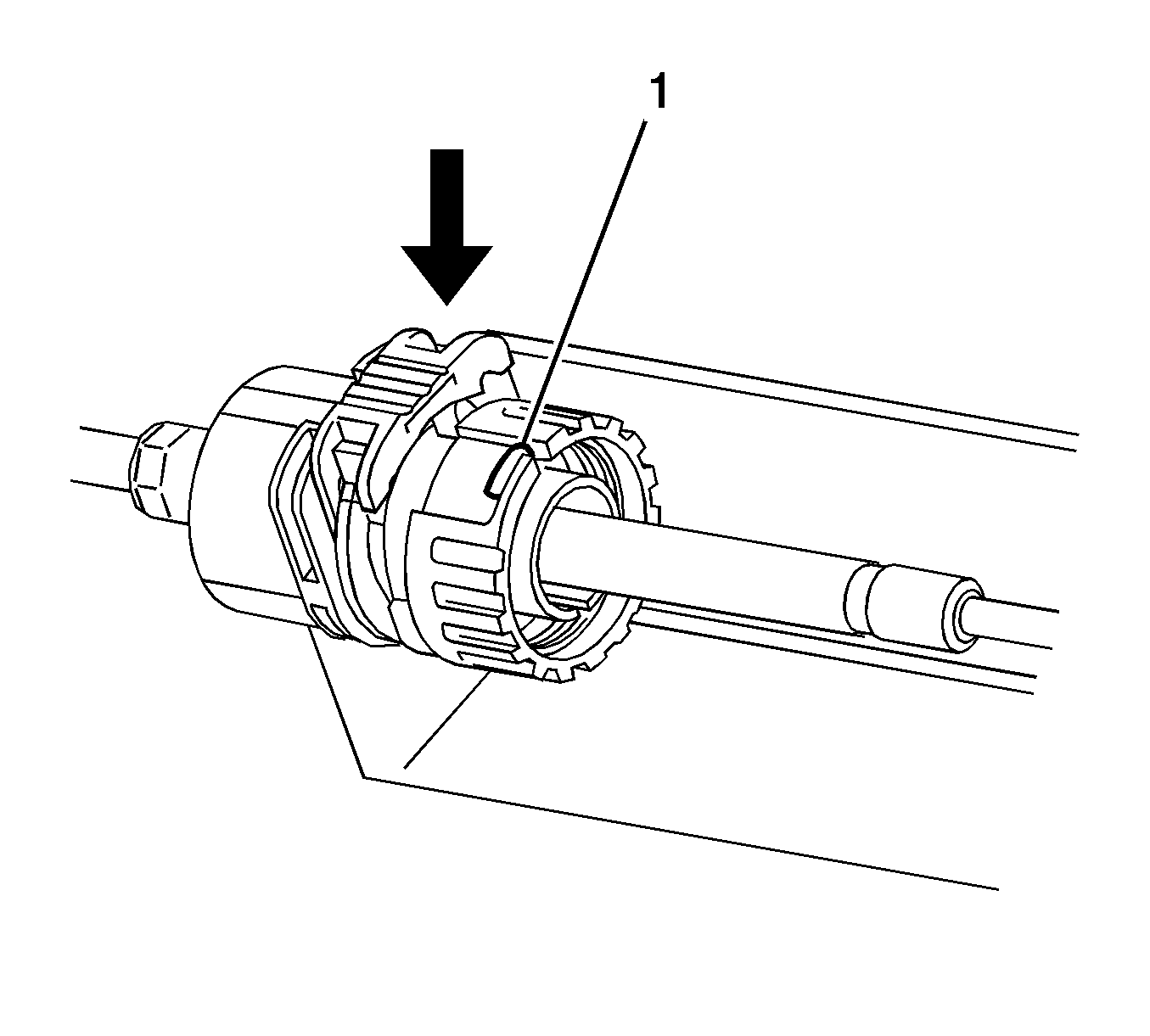
Note: If the stopper cannot be pushed in, slightly turn the nut (1) clockwise and then push in the stopper again.


Note: Check that the lock piece (1) is pulled up.

Note: Securely push in the lock piece until it locks.

