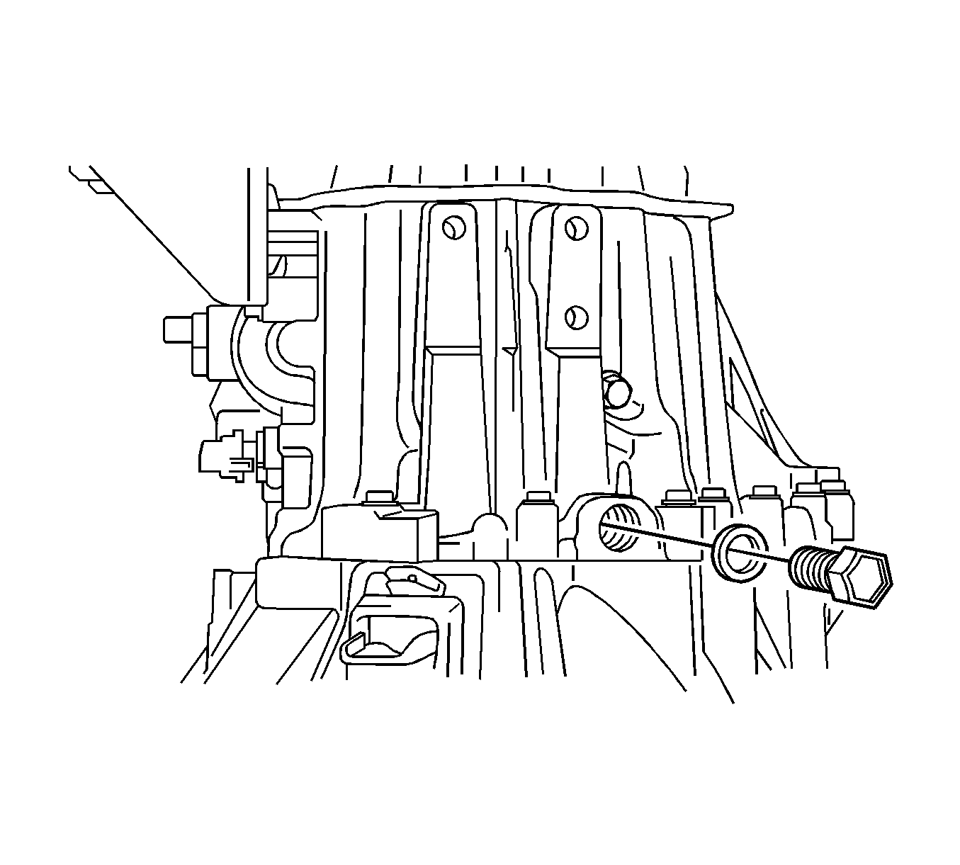
- Remove the manual transmission filler plug and gasket from the manual transmission case.
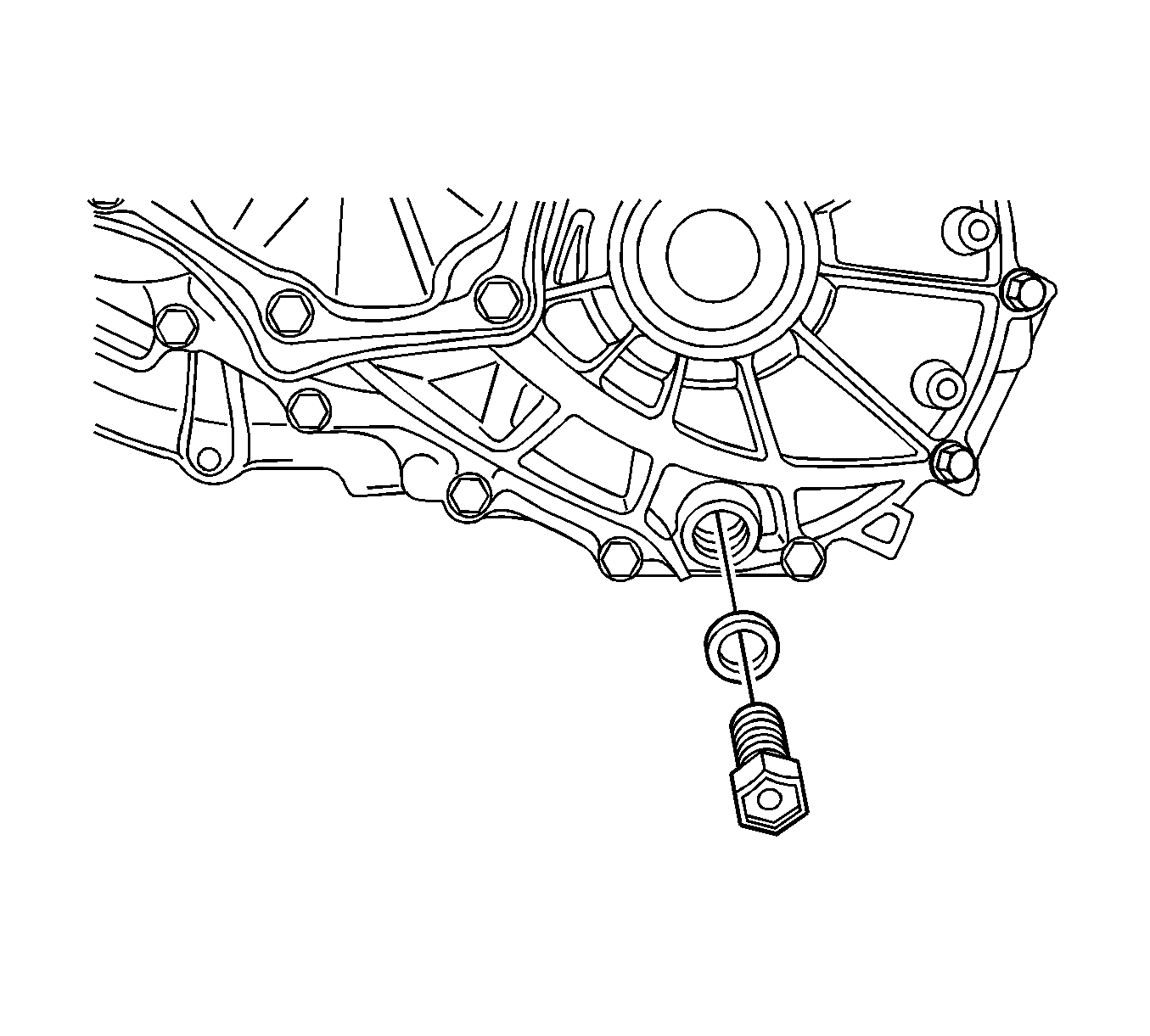
- Remove the drain plug sub-assembly and gasket from the manual transmission case.
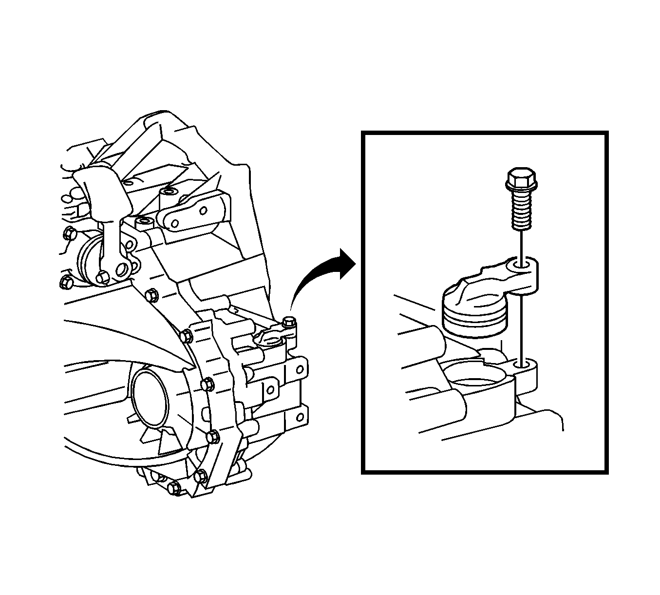
- Remove the bolt and speedometer driven hole cover sub-assembly from the transaxle case.
- Remove the O-ring from the speedometer driven hole cover sub-assembly.
- Separate the back-up light switch wire harness from the clamps.
- Remove the back-up light switch assembly and gasket from the manual transmission case.
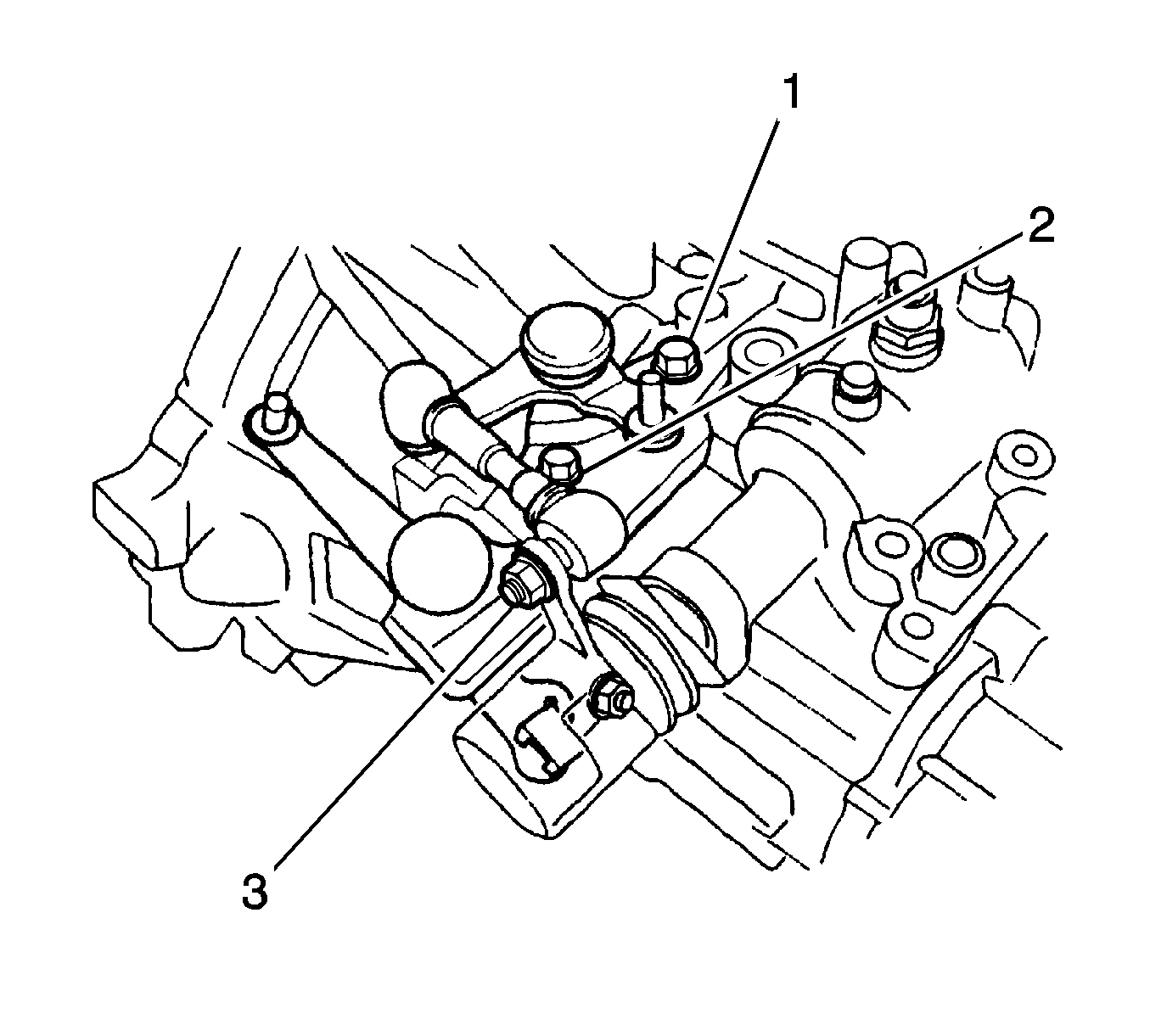
- Remove the bolts (1, 2), nut (3), and selecting bellcrank assembly from the manual transmission case.
- Remove the control bellcrank dust cover.
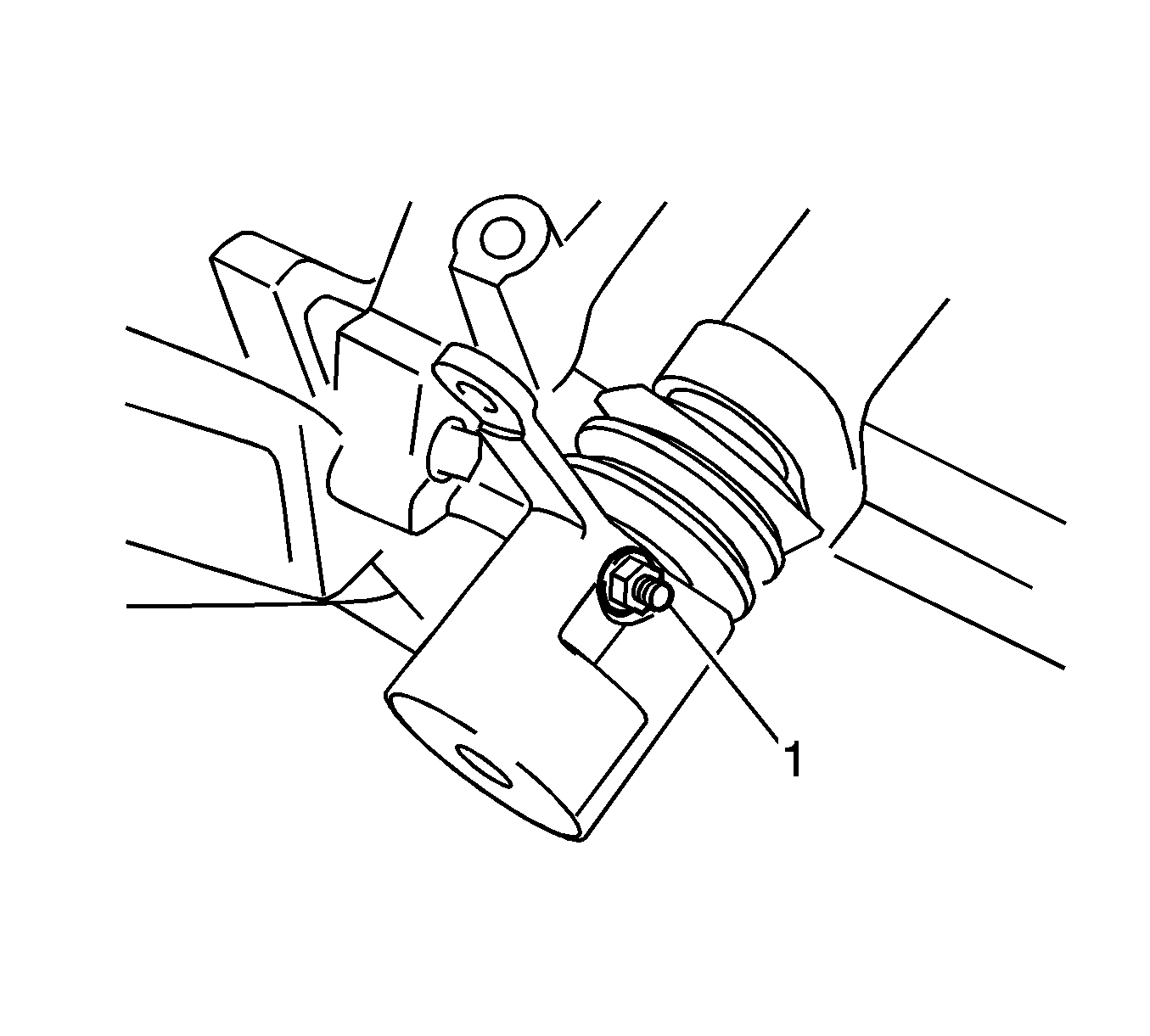
- Remove the nut (1) and washer.
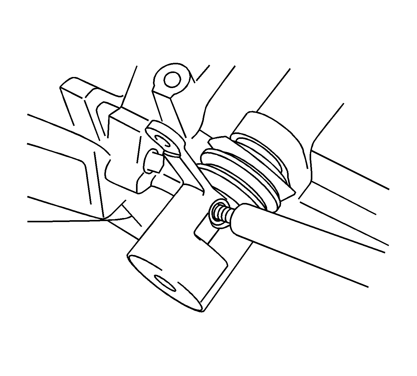
- Using a brass bar and a hammer, remove the lock pin.
- Remove the floor shift control shift lever and dust boot.
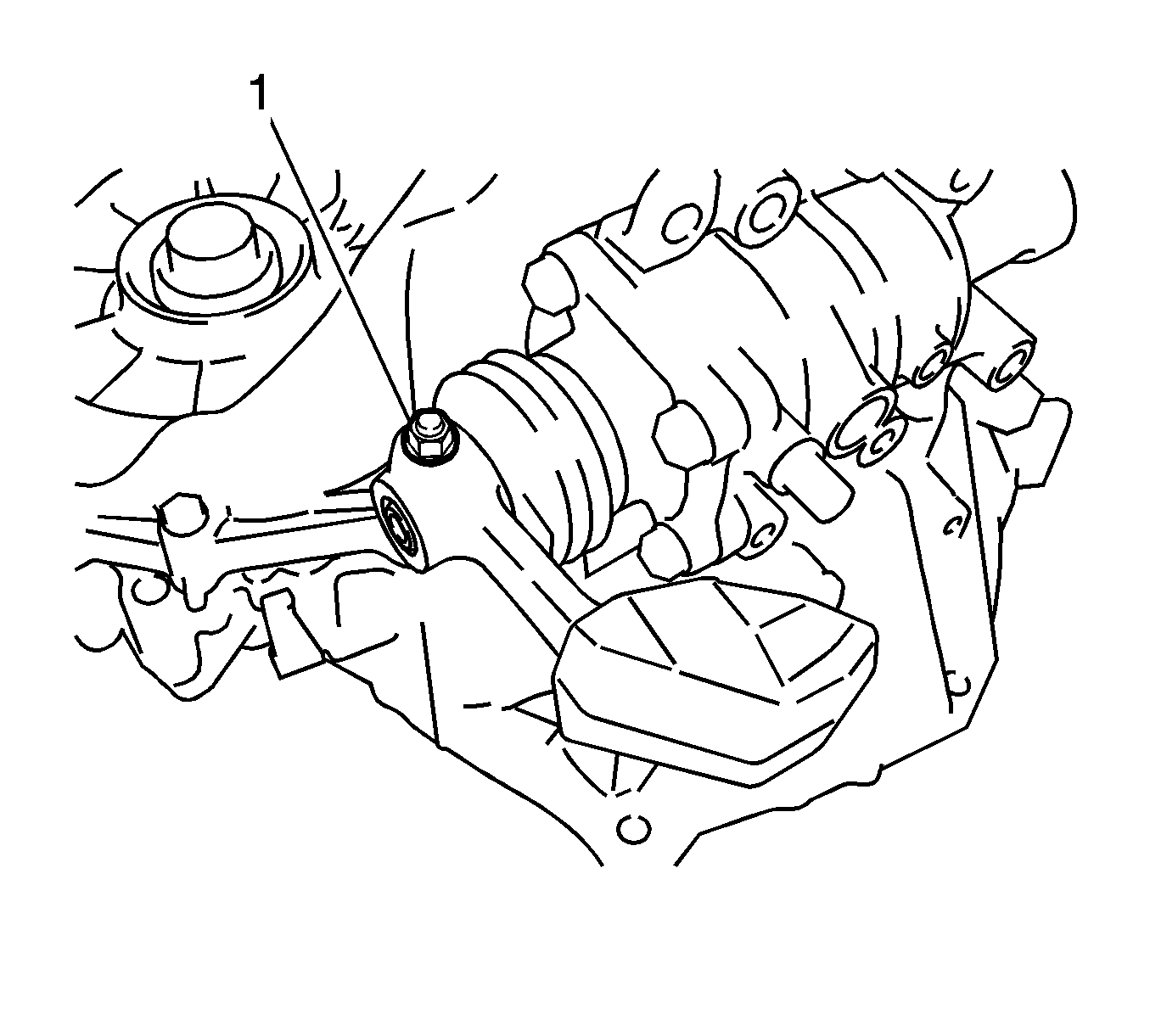
- Remove the nut (1) and washer.
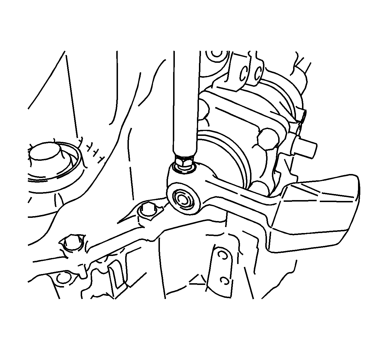
- Using a brass bar and a hammer, remove the lock pin.
- Remove the shift lever damper and dust boot.
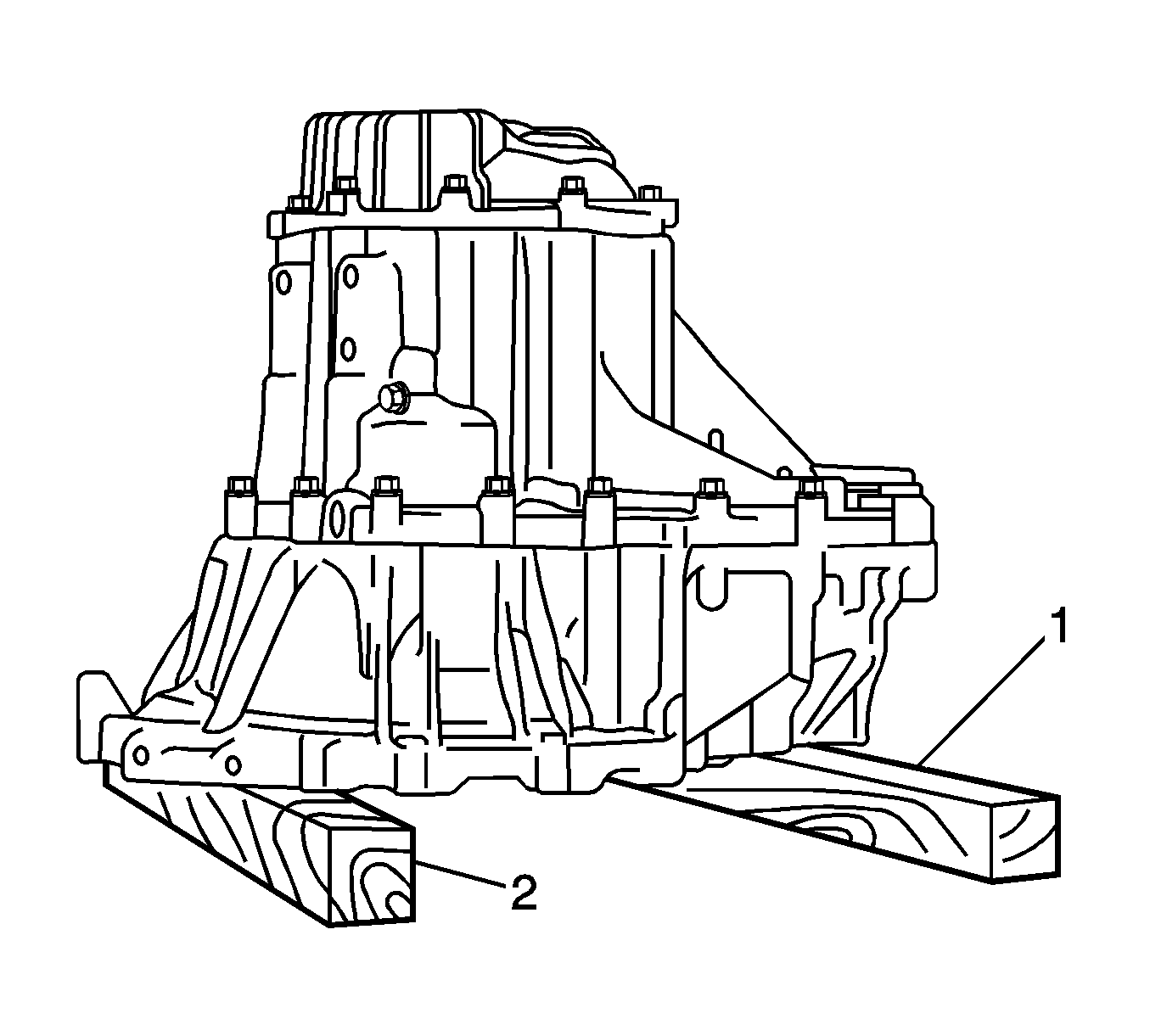
- Place the manual transaxle assembly on wooden blocks (1, 2).
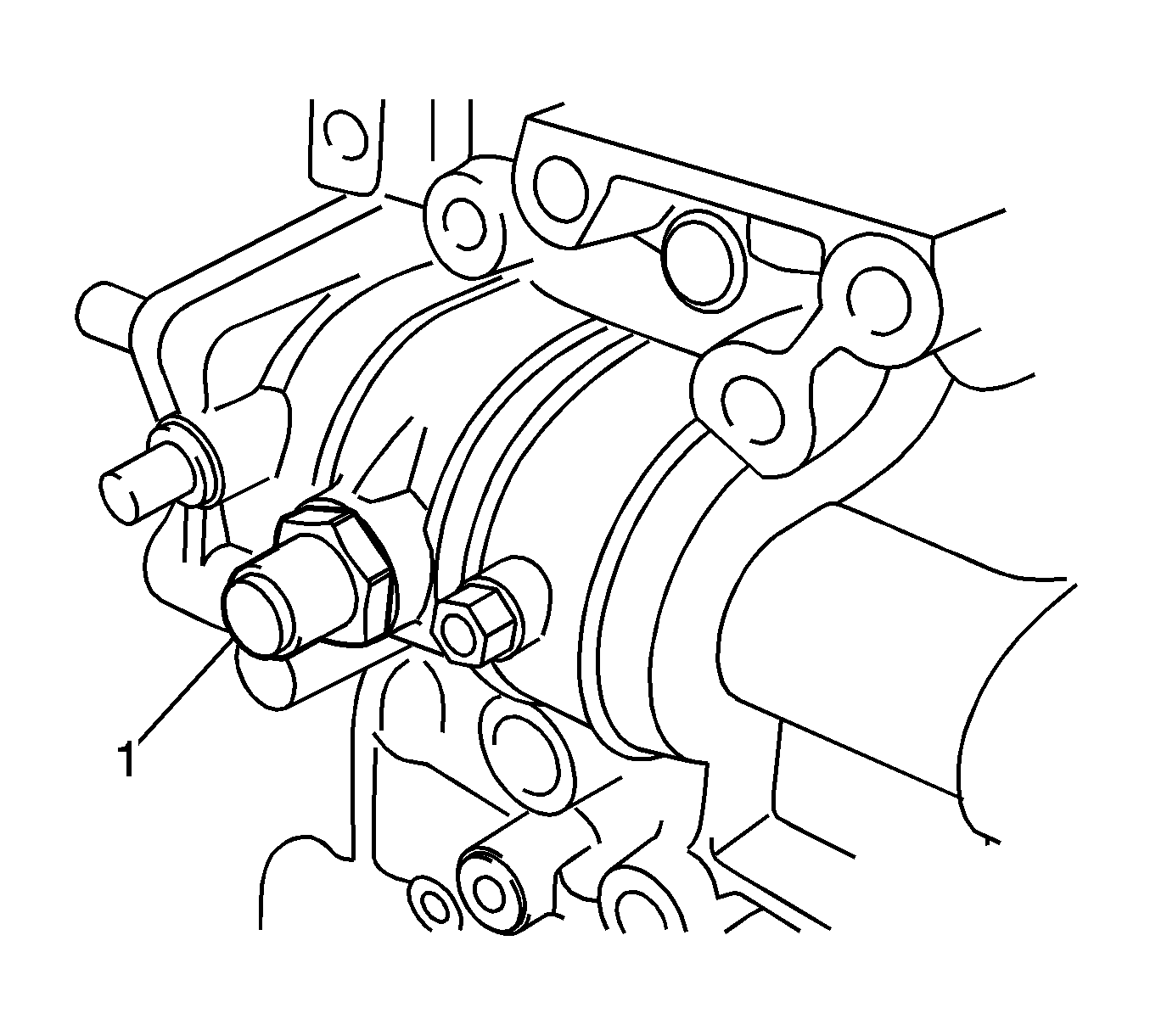
- Remove the No. 1 lock ball assembly (1) from the manual transmission case.
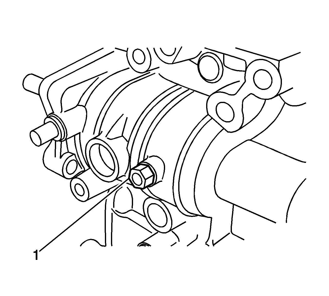
- Remove the shift guide pin (1) and washer from the manual transmission case.
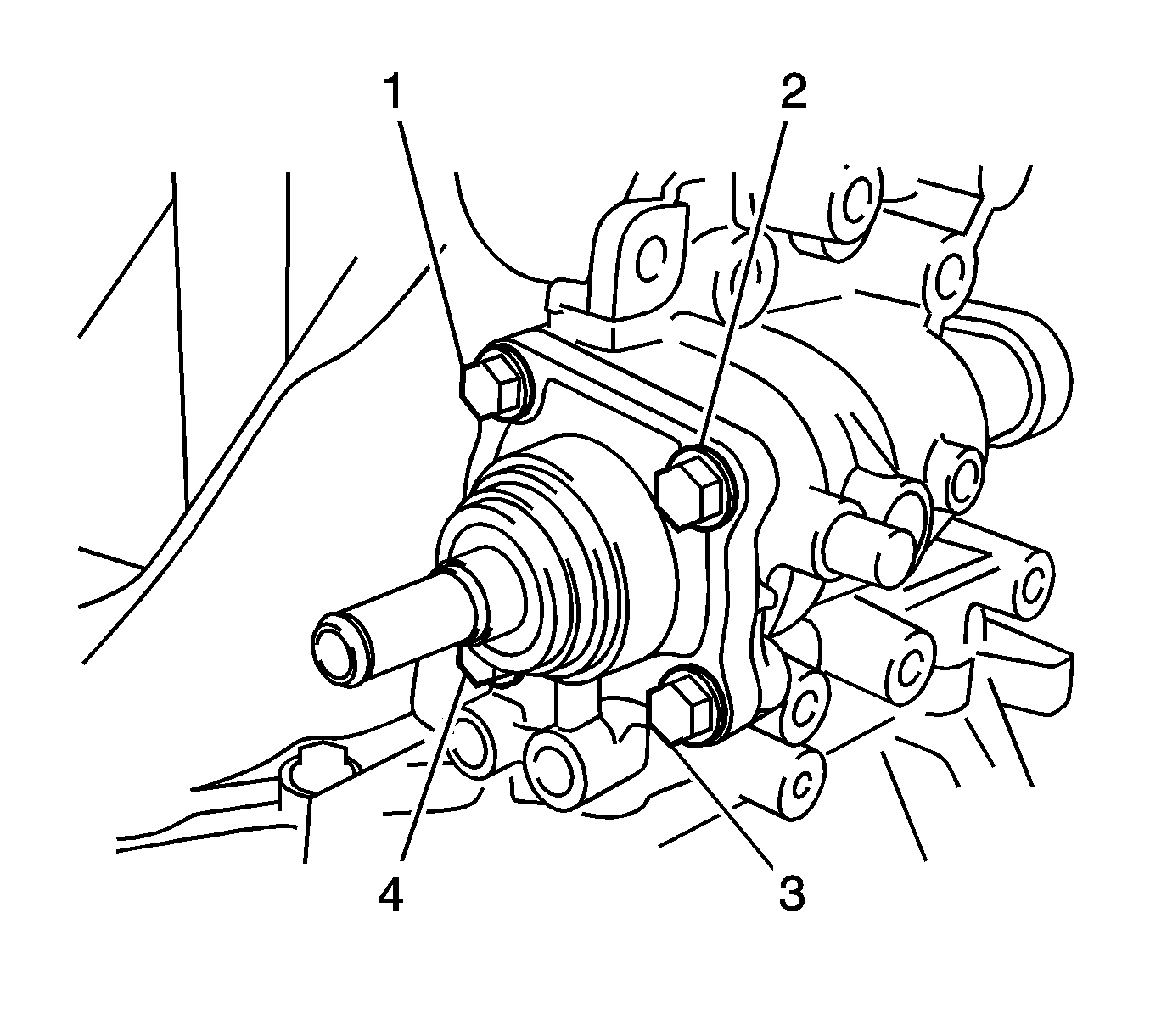
- Remove the bolts (1-4), control shaft cover and gasket from the manual transmission case.
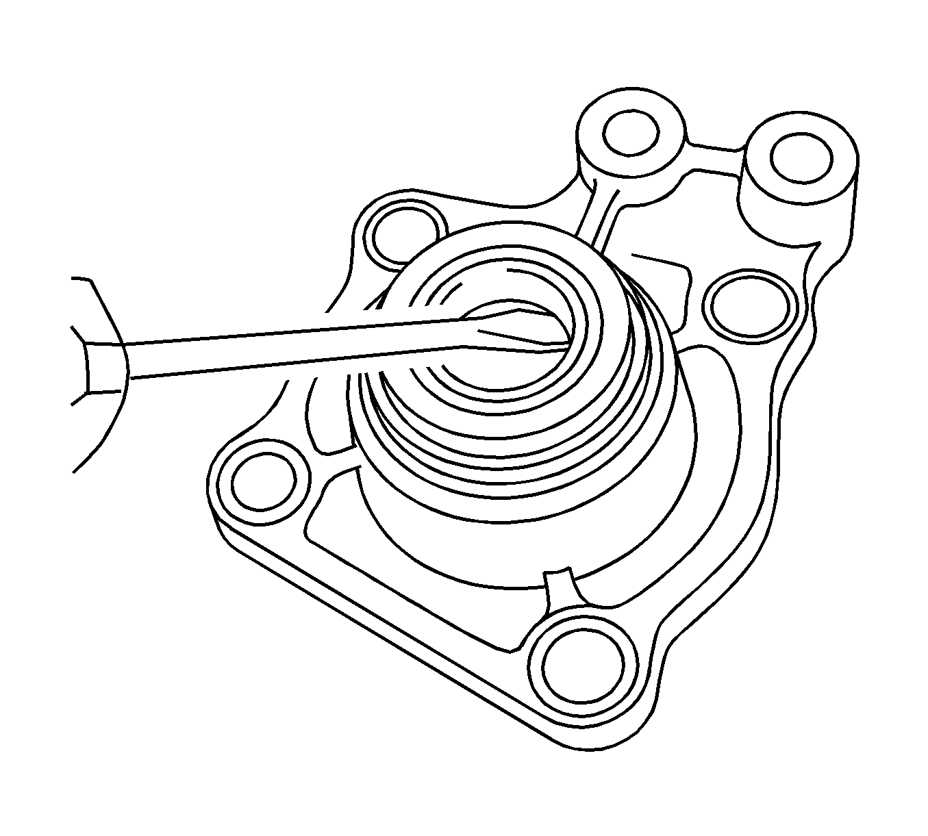
- Using a screwdriver, remove the control shaft cover oil seal from the control shaft cover.
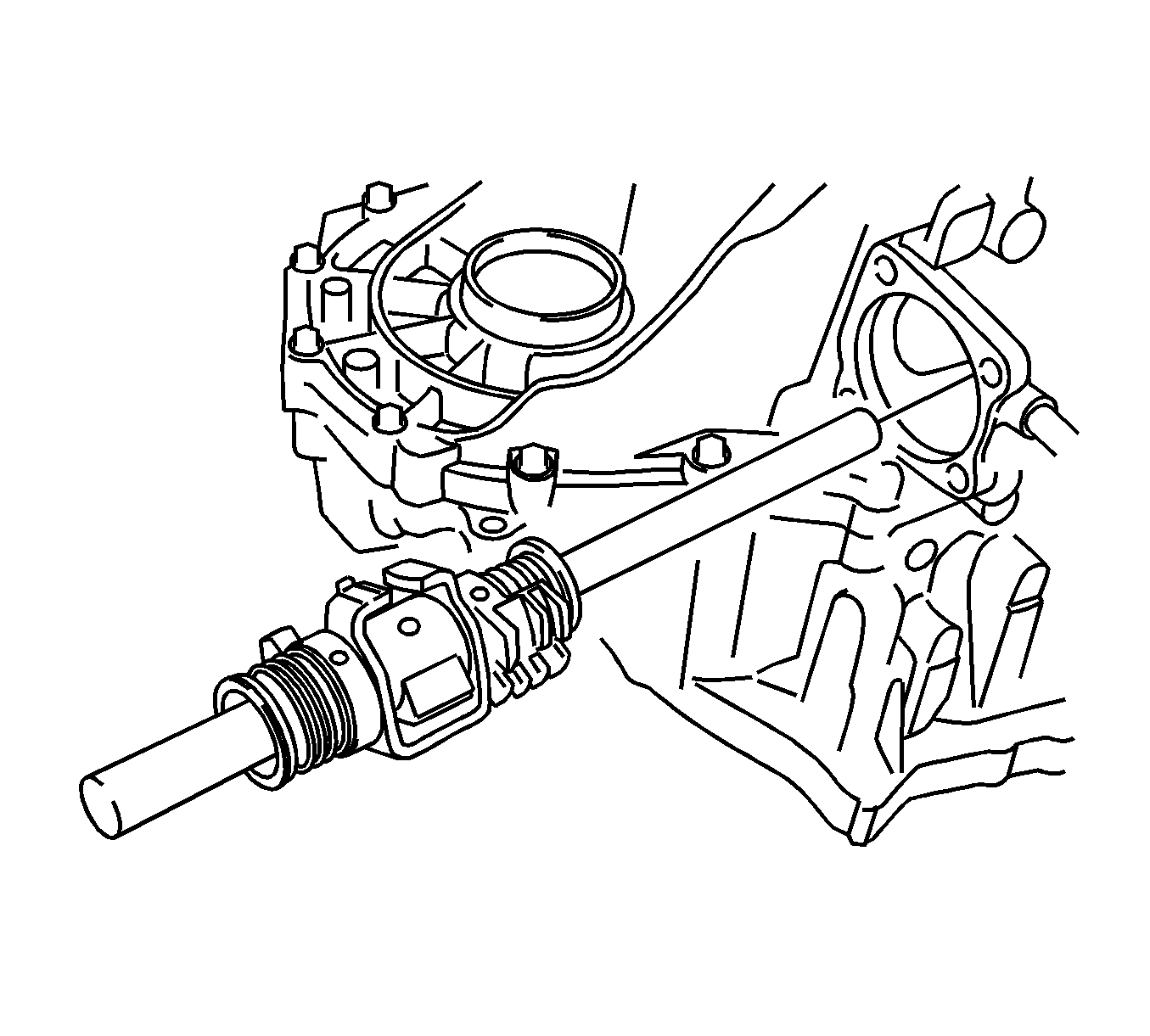
- Remove the shift and select lever shaft assembly from the manual transmission case.
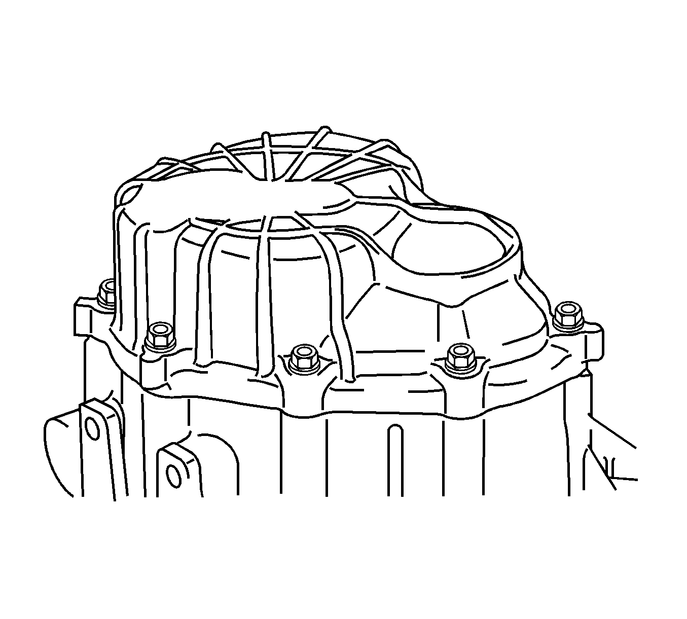
- Remove the bolts.
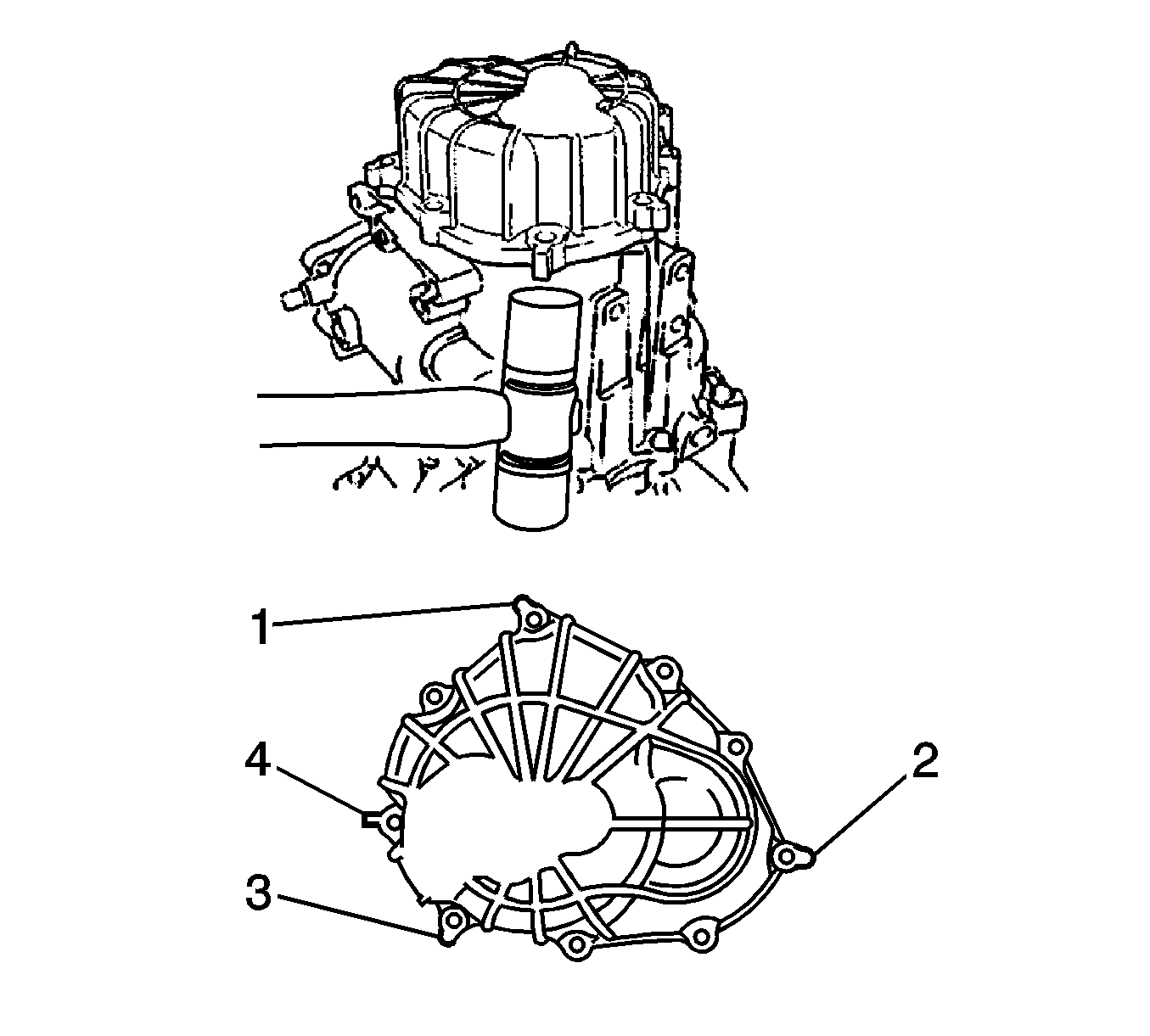
Note: Do not damage the manual transmission case.
- Using a plastic hammer, carefully tap the projections (1, 2, 3, 4) of the manual transmission case cover sub-assembly to remove the manual transmission case cover from the manual transmission case.
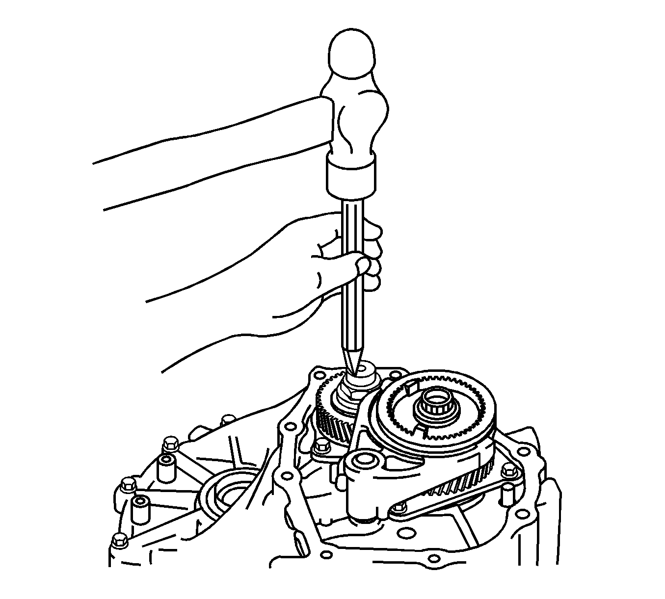
- Using a chisel and a hammer, loosen the staked part of the manual transmission output shaft rear set nut.
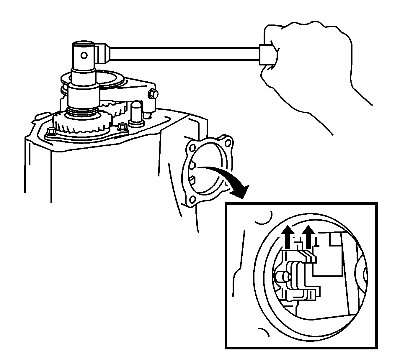
- Engage the gears simultaneously to lock the transmission.
- Remove the manual transmission output shaft rear set nut.
- Disengage the gears.
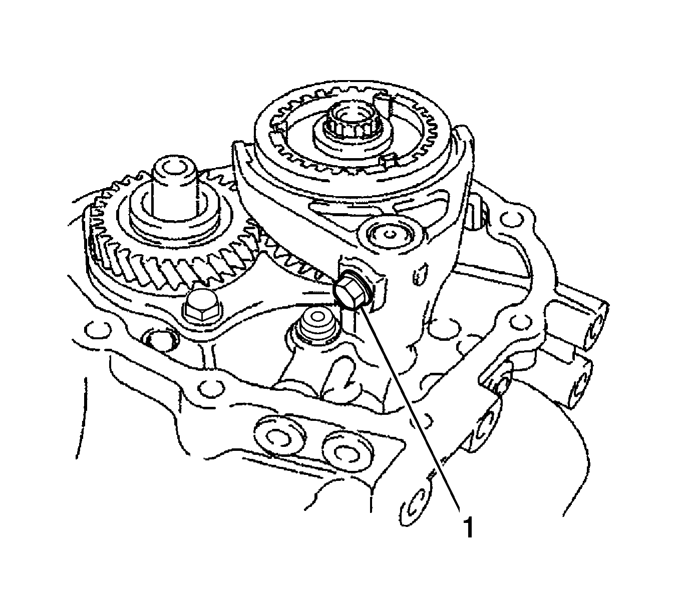
- Remove the gear shift fork lock bolt (1) from the No. 3 gear shift fork.
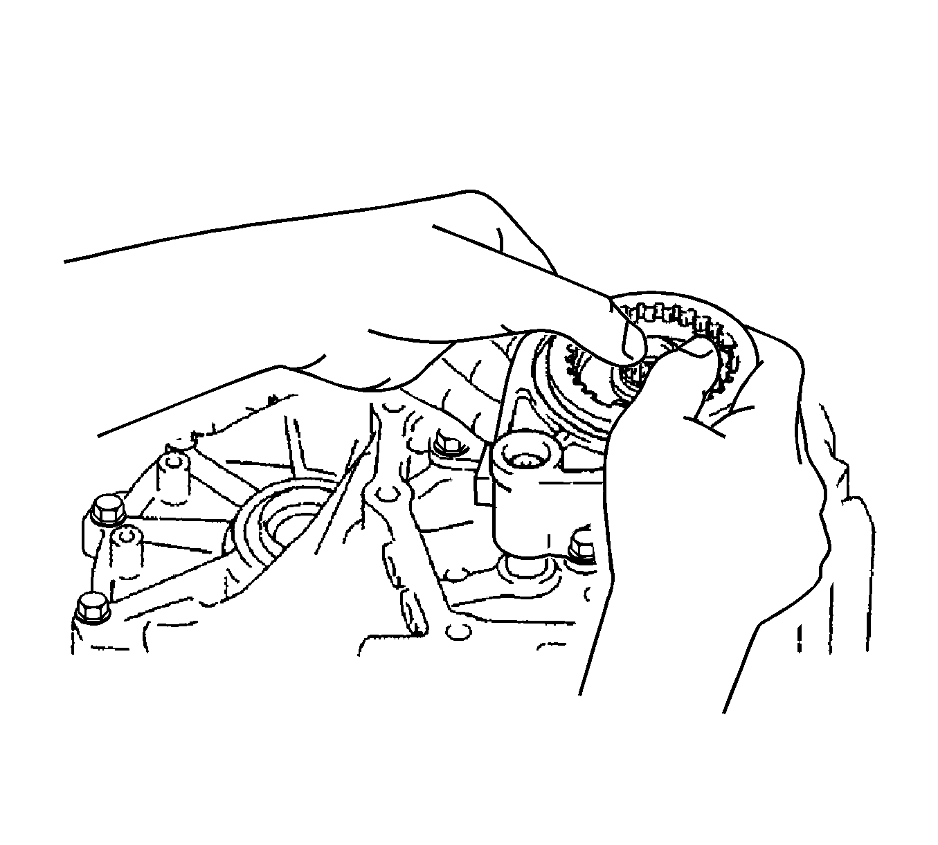
- Remove the No. 3 transmission hub sleeve with the No. 3 gear shift fork from the No. 3 transmission clutch hub.
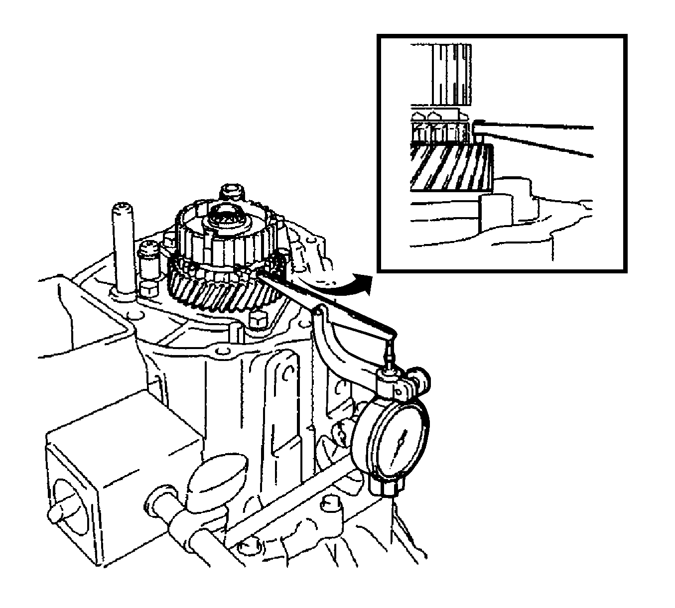
- Using a dial indicator, measure the 5th gear thrust clearance.
Specifications
| • | Standard clearance - 0.10-0.55 mm (0.0039-0.0217 in) |
| • | Maximum clearance - 0.55 mm (0.0217 in) |
- If the clearance exceeds the maximum, replace the No. 3 transmission clutch hub, 5th gear or input shaft rear radial ball bearing.
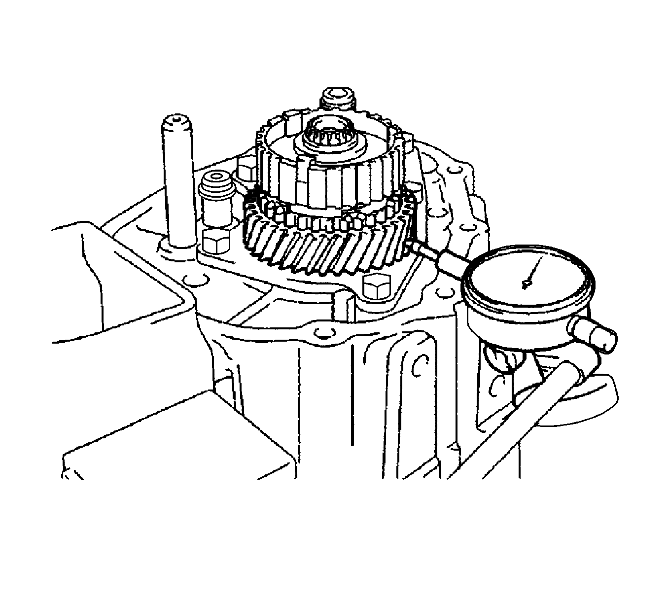
- Using a dial indicator, measure the 5th gear radial clearance.
Specifications
| • | Standard clearance, NSK made bearing - 0.015-0.056 mm (0.0005-0.0022 in) |
| • | Standard clearance, KOYO made bearing - 0.015-0.058 mm (0.0005-0.0022 in) |
| • | Maximum clearance, NSK made bearing - 0.056 mm (0.0022 in) |
| • | Maximum clearance, KOYO made bearing - 0.058 mm (0.0022 in) |
- If the clearance exceeds the maximum, replace the 5th gear, 5th gear needle roller bearing or input shaft.
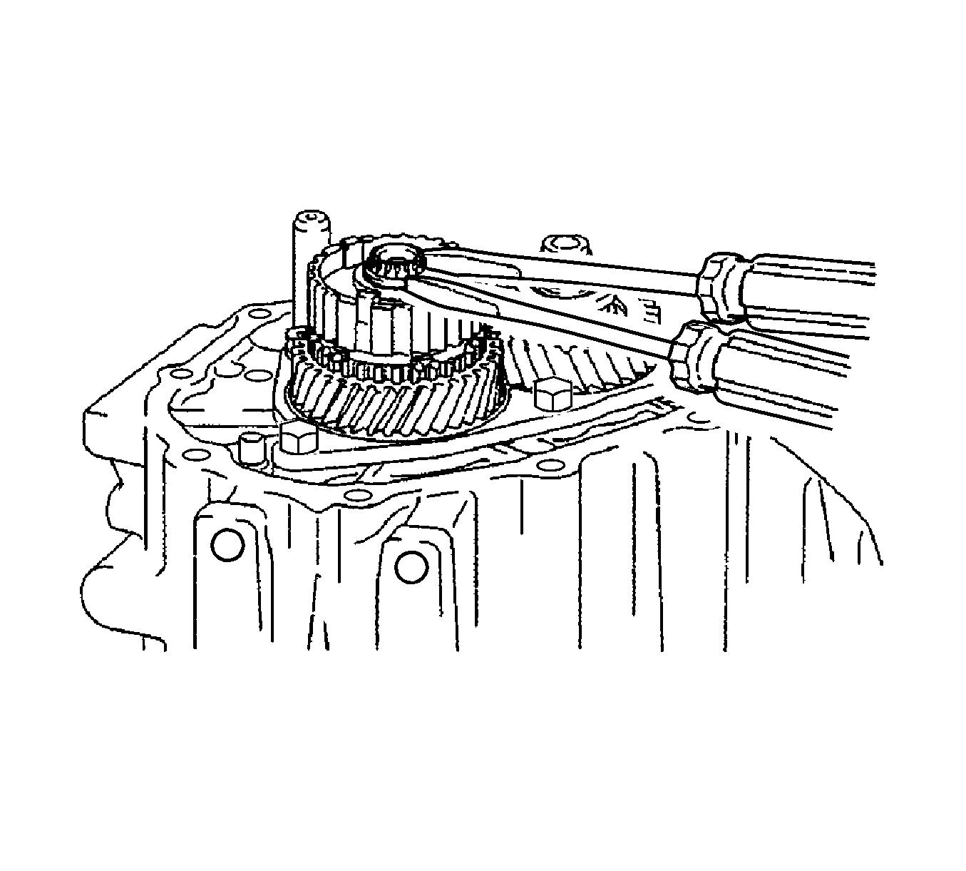
Note: Use a shop rag or piece of cloth to keep the snap ring from flying off.
- Using 2 screwdrivers and a hammer, tap out the snap ring.
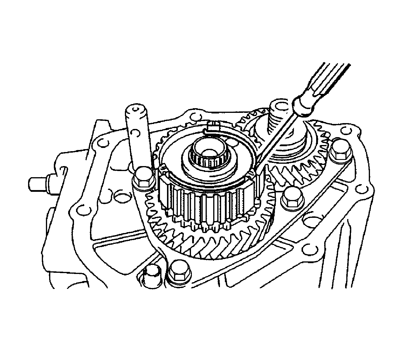
- Using a screwdriver, remove the synchromesh shifting key spring from the No. 3 transmission clutch hub.
- Using a suitable puller, remove the No. 3 transmission clutch hub, 5th gear, and No. 3 synchronizer ring from the input shaft.
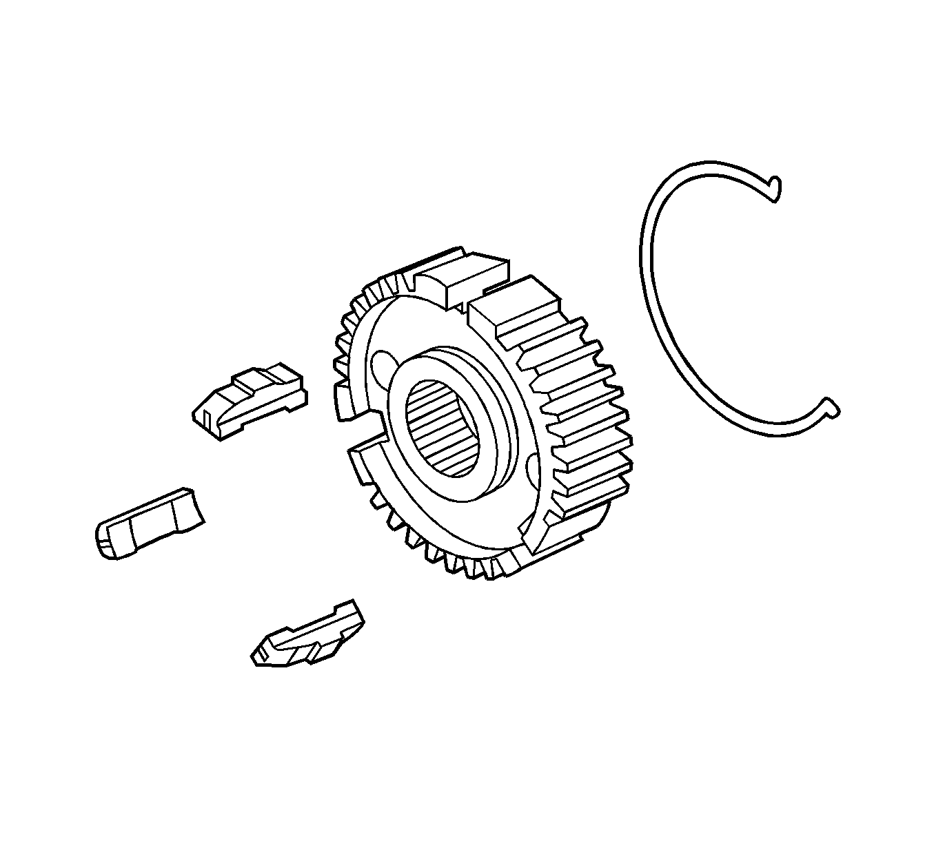
- Remove the synchromesh shifting keys and synchromesh shifting key spring from the No. 3 transmission clutch hub.
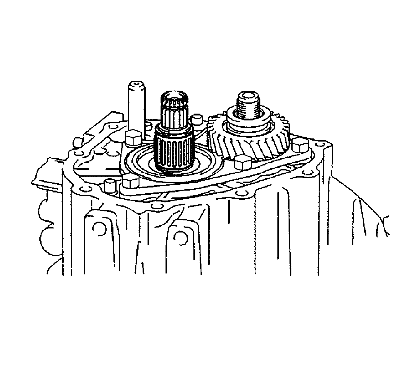
- Remove the 5th gear needle roller bearing and 5th gear bearing spacer from the input shaft.
- Using a suitable puller, remove the 5th driven gear from the output shaft.
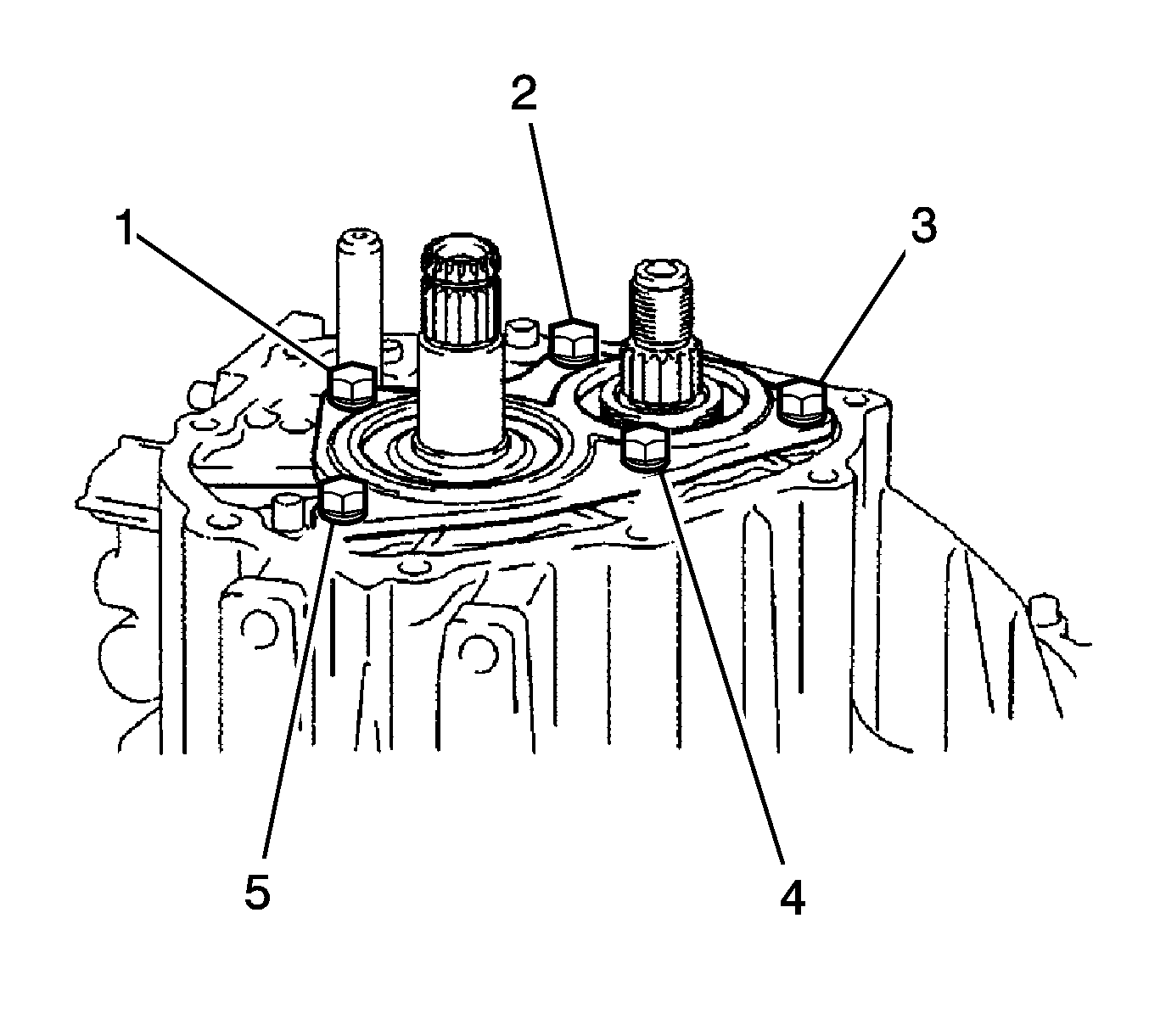
- Remove the bolts (1-5) and rear bearing retainer from the manual transmission case.
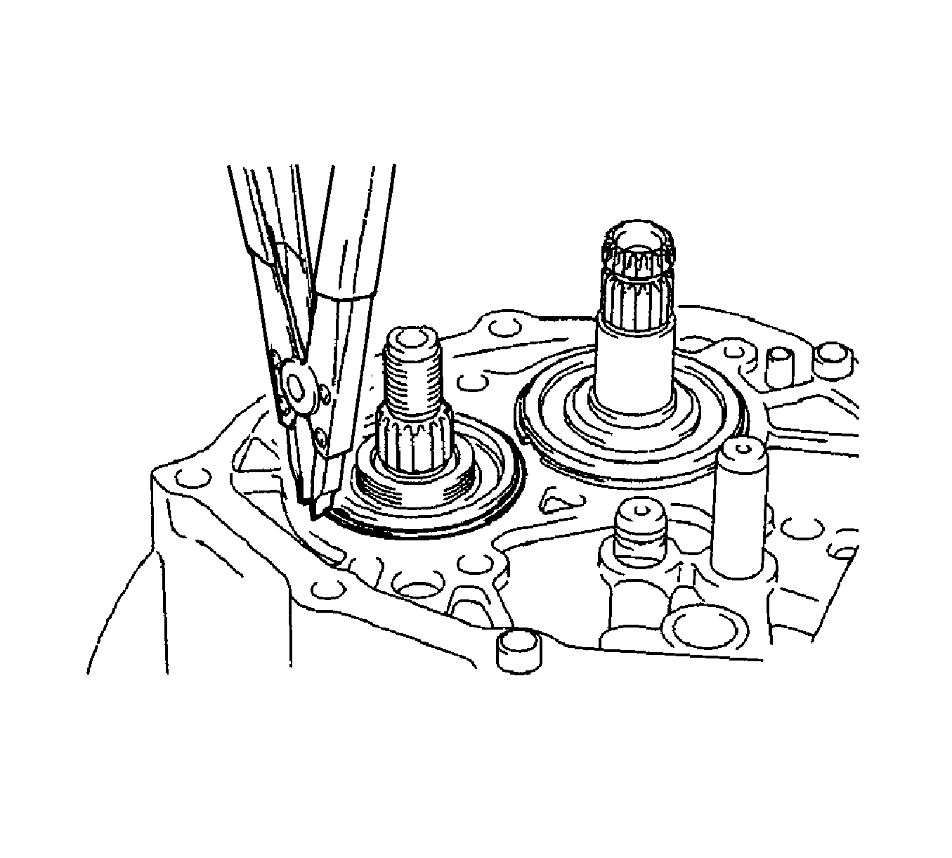
- Using a snap ring expander, remove the output shaft rear bearing hole snap ring from the output shaft.
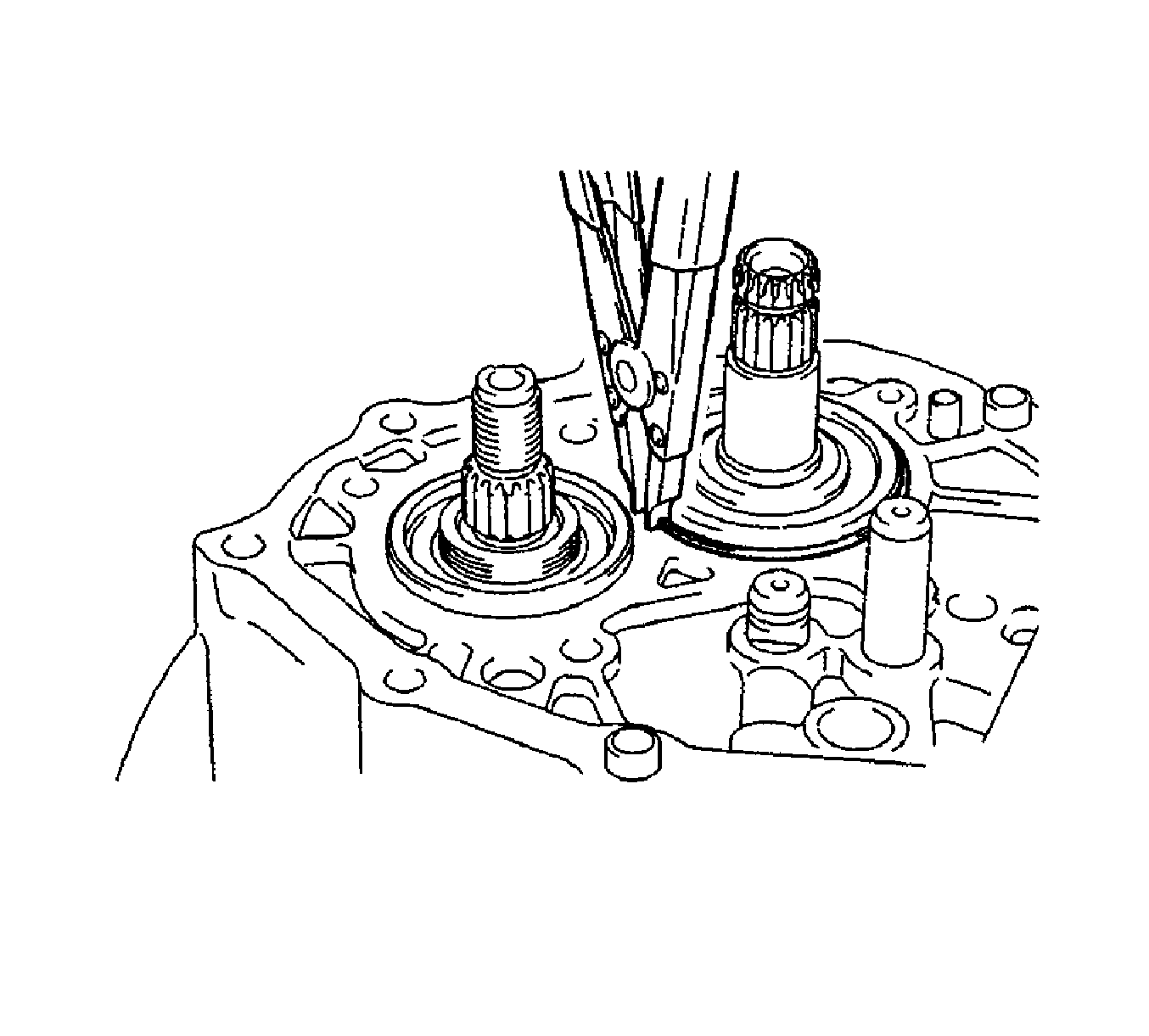
- Using a snap ring expander, remove the input shaft rear bearing hole snap ring from the input shaft.
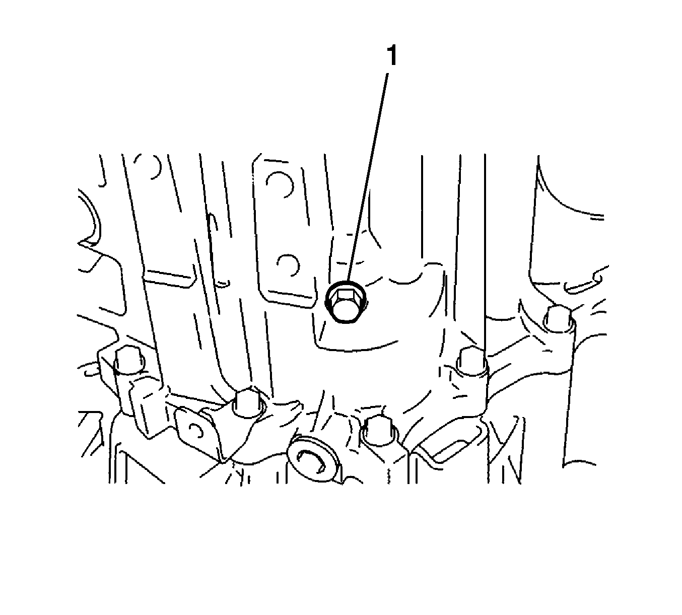
- Remove the reverse idler gear shaft bolt (1) and gasket from the manual transmission case.
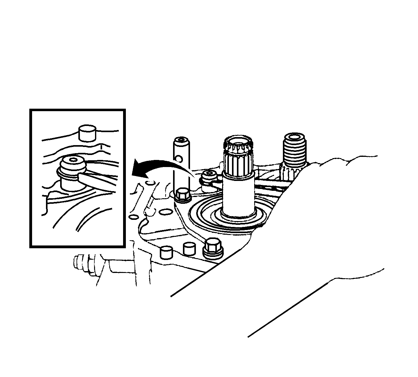
Note: Use a shop rag or piece of cloth to keep the snap ring from flying off.
- Using 2 screwdrivers and a hammer, tap out the snap ring from the No. 2 gear shift fork shaft.
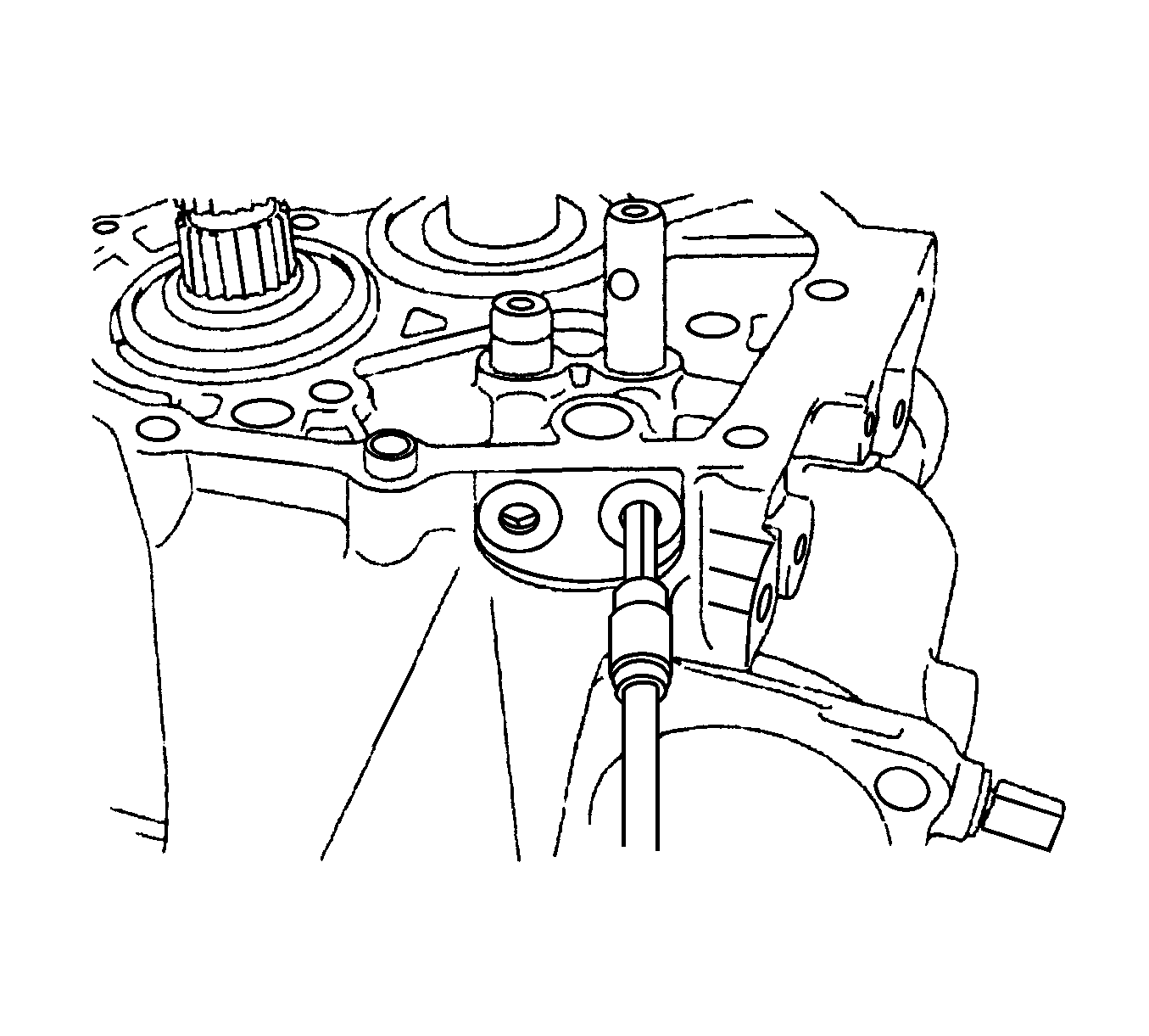
- Using a hexagon wrench, remove the shift detent ball plugs from the manual transmission case.
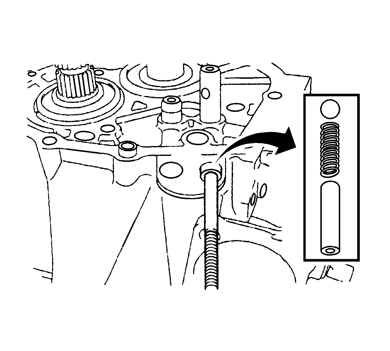
- Using a magnetic pick-up tool, remove the shift spring seats, shift detent ball springs, and shift detent balls from the manual transmission
case.
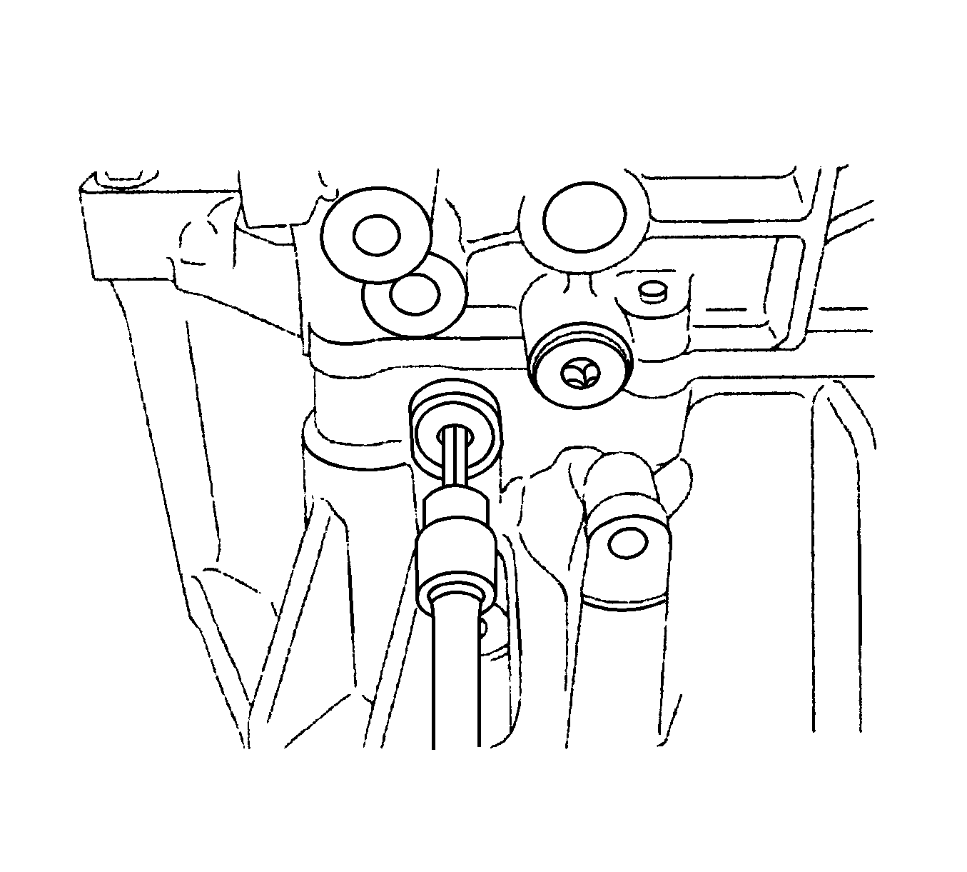
- Using a hexagon wrench, remove the shift detent ball plug from the transaxle case.
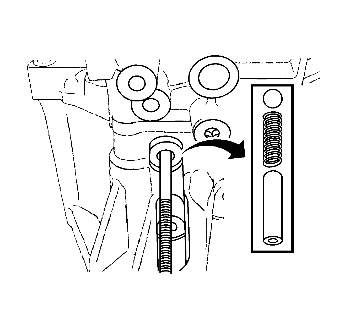
- Using a magnetic pick-up tool, remove the seat, spring, and ball from the transaxle case.
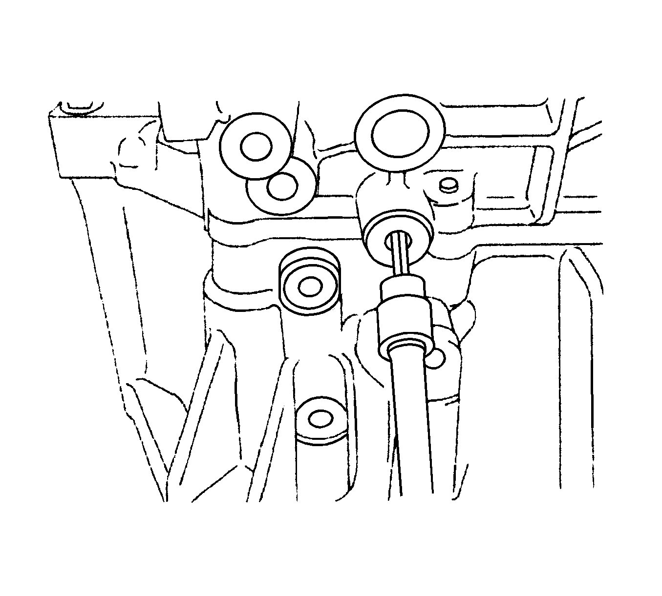
- Using a hexagon wrench, remove the No. 2 lock ball assembly from the manual transmission case.
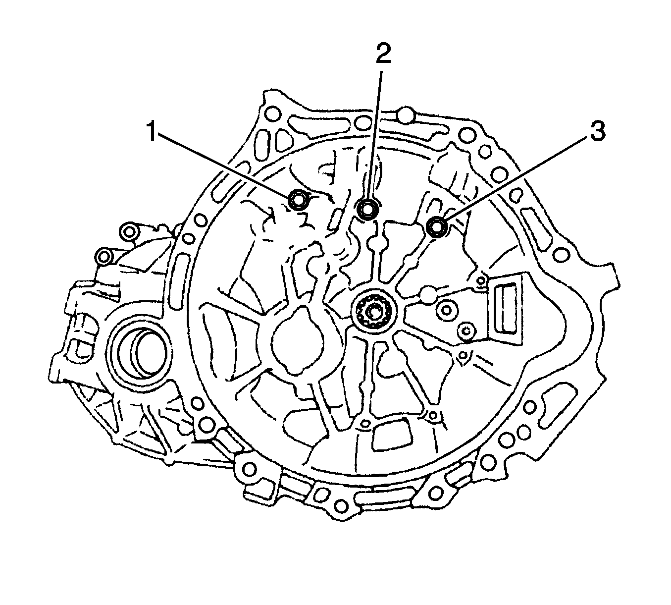
- Remove the bolts (1-3) from the transaxle case.
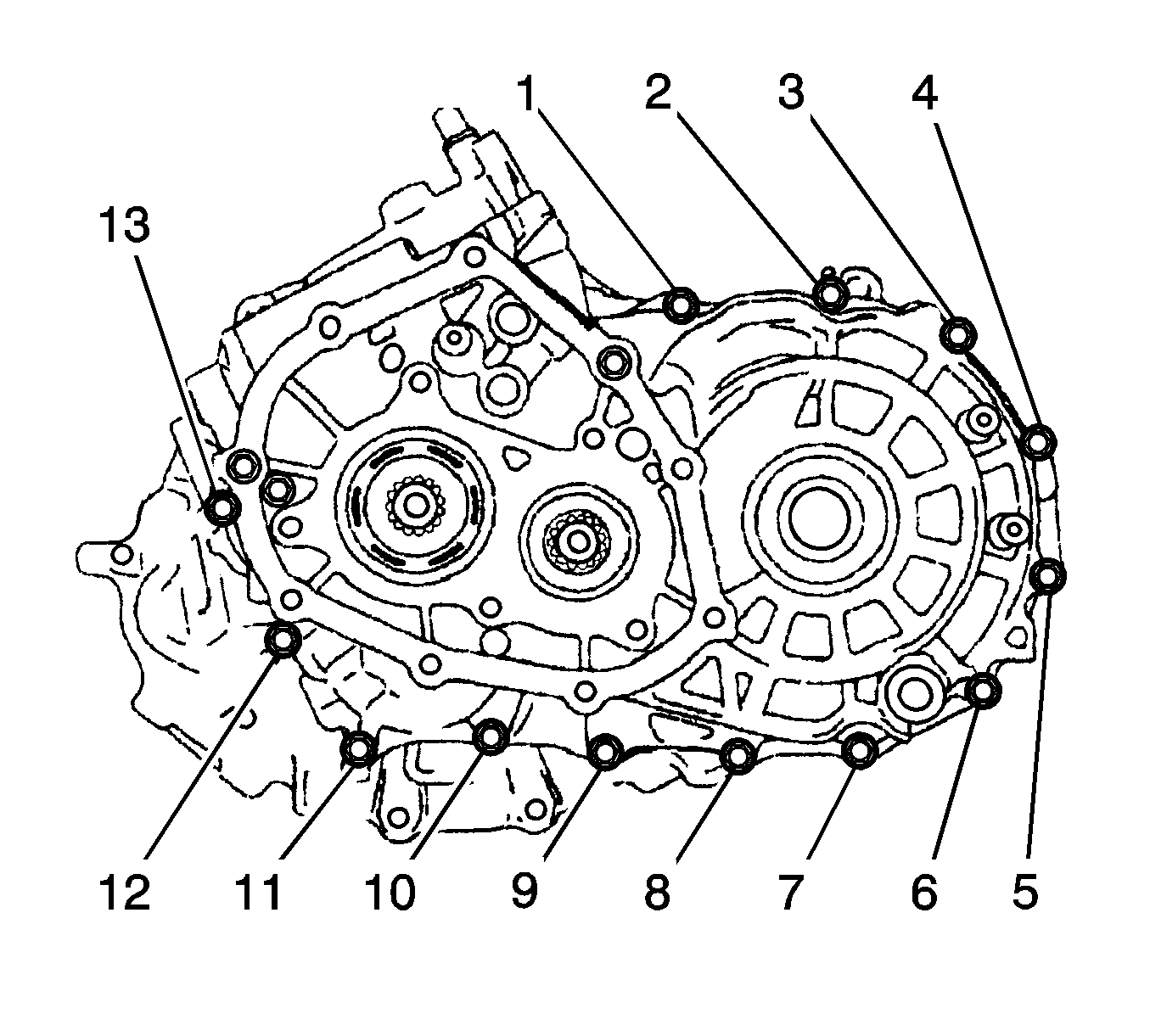
- Remove the bolts (1-13) from the manual transmission case.
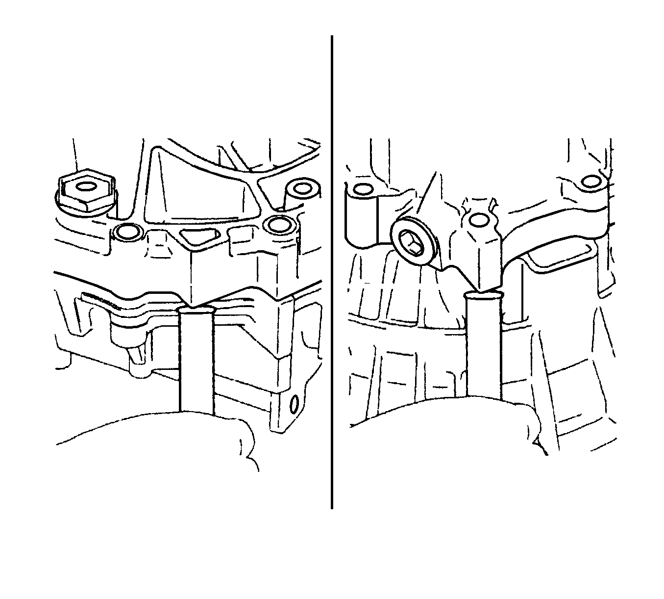
- Using a brass bar and a hammer, carefully tap the projections of the manual transmission case to remove the transmission case from
the transaxle case.
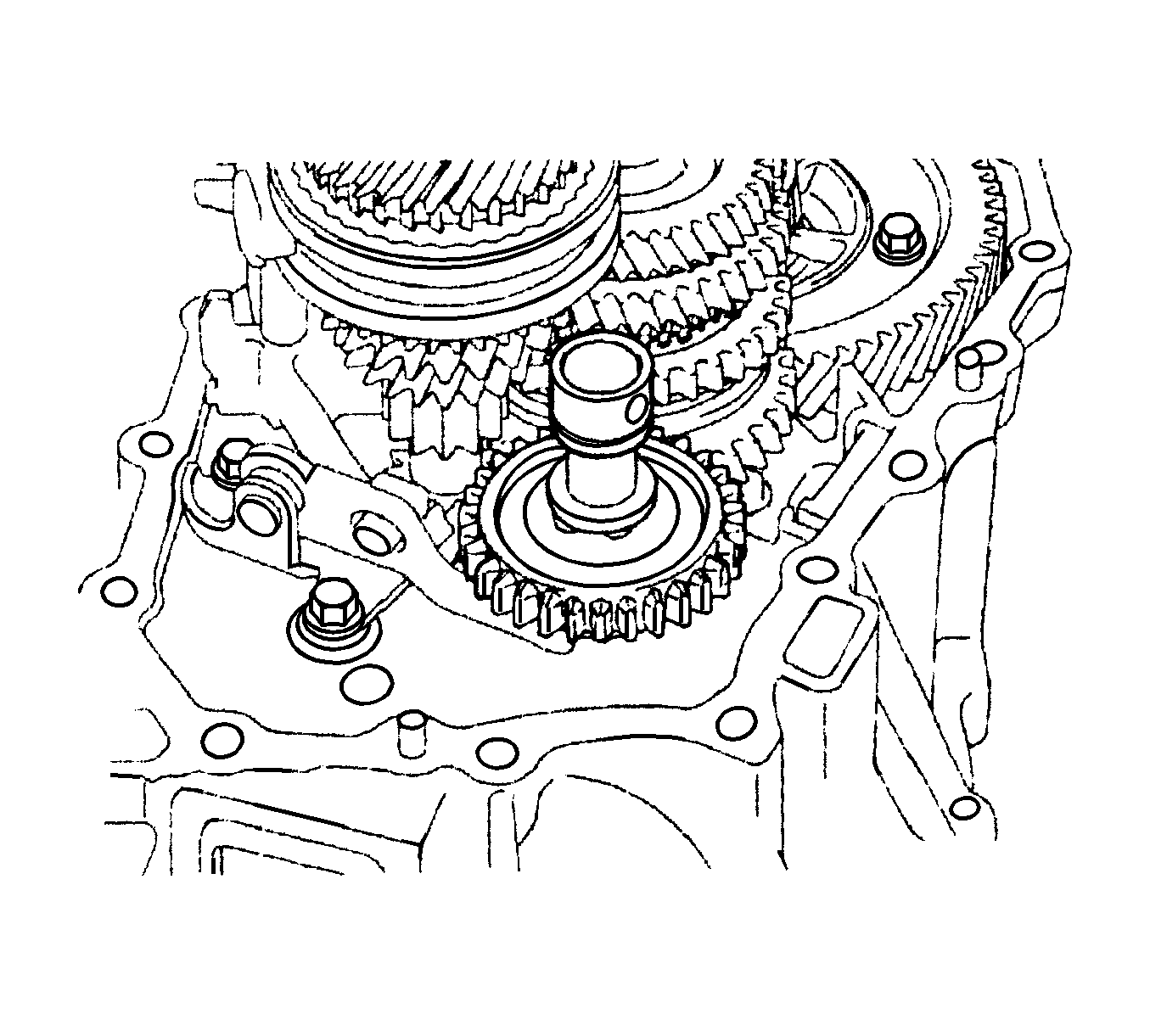
- Remove the reverse idler gear sub-assembly, thrust washer, and reverse idler gear shaft from the transaxle case.
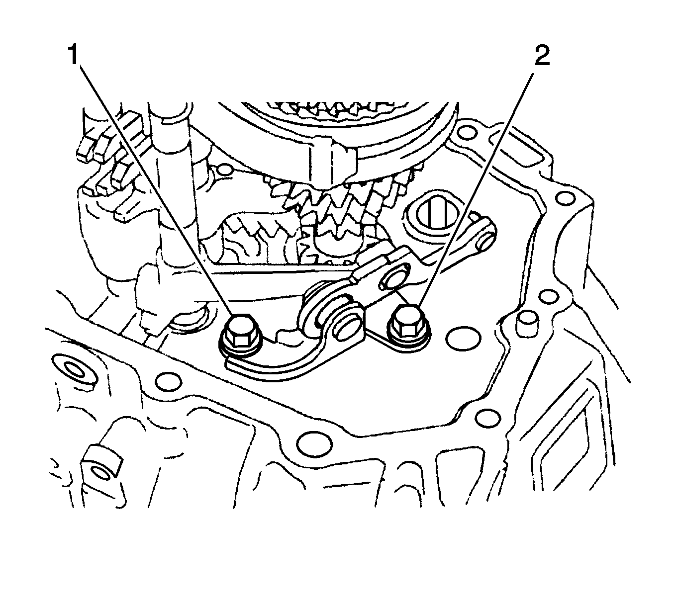
- Remove the bolts (1, 2) and reverse shift arm bracket assembly from the transaxle case.
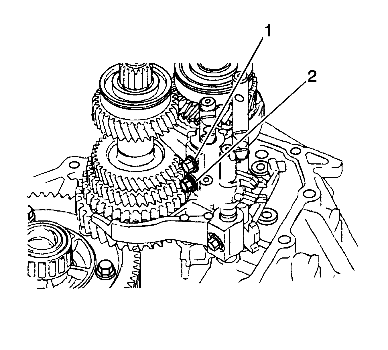
- Remove the bolts (1, 2) from the No. 2 gear shift fork and No. 1 gear shift head.
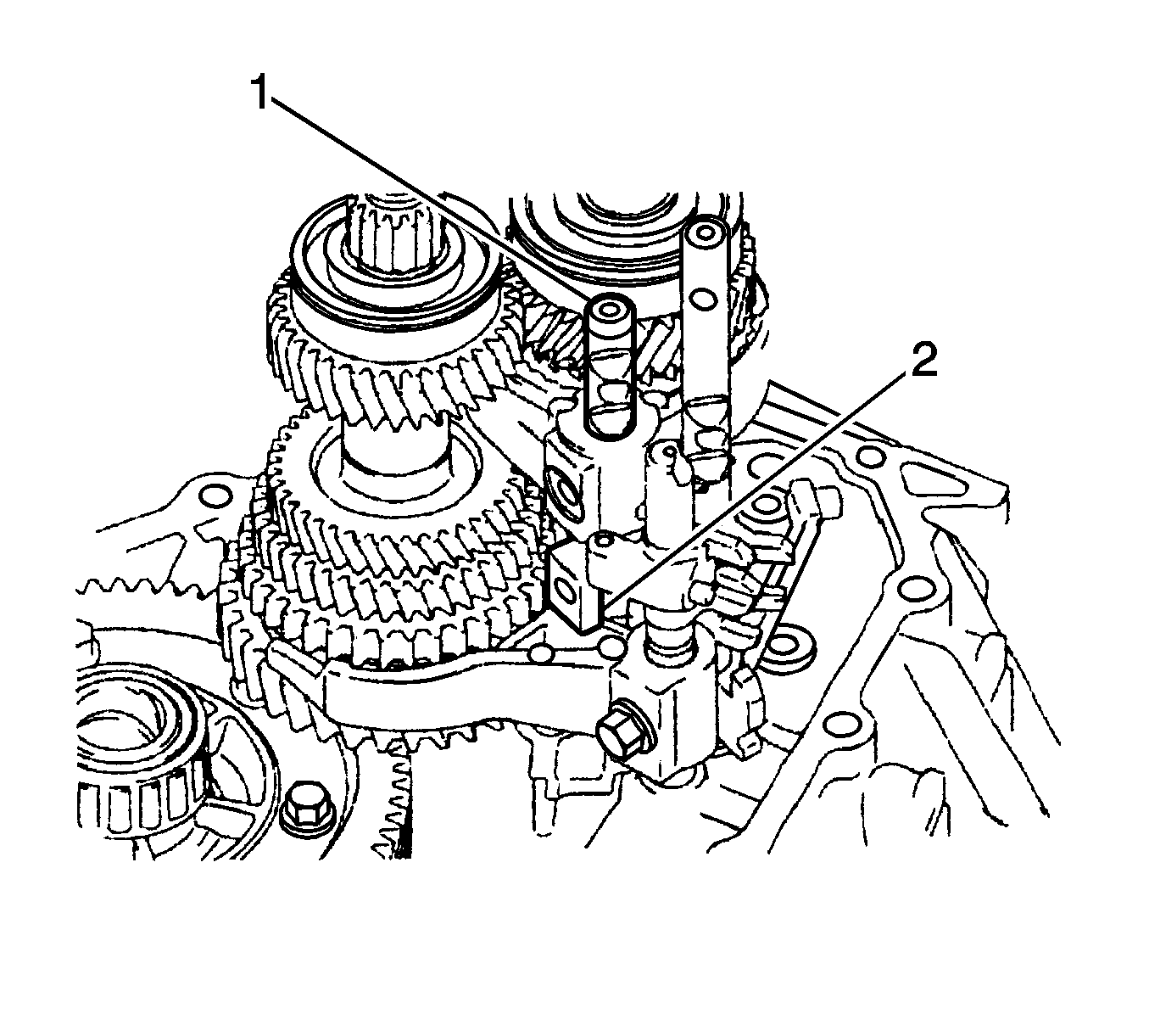
- Remove the No. 2 gear shift fork shaft (1) and No. 1 gear shift head from the transaxle case.
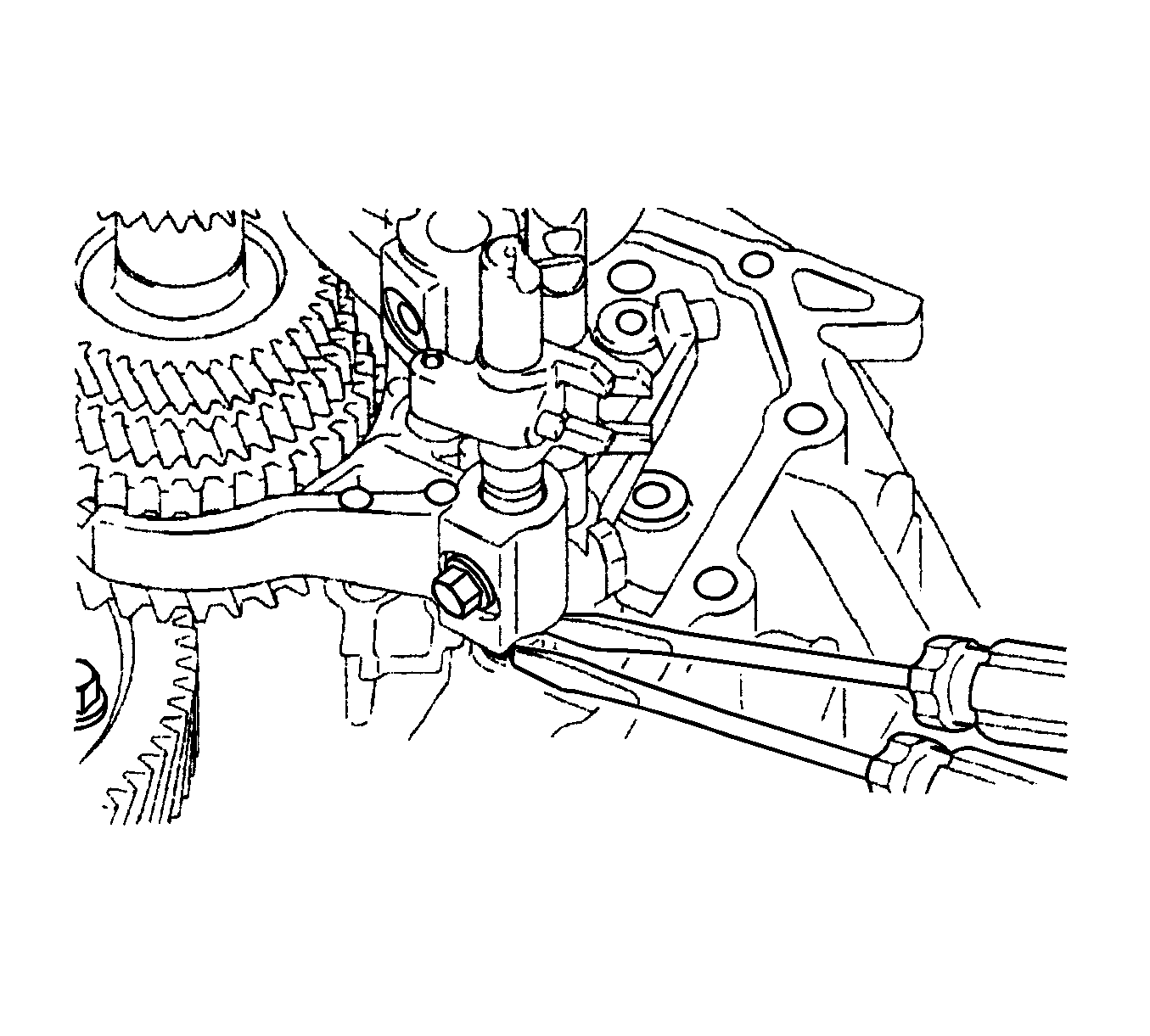
Note: Use a shop rag or piece of cloth to keep the snap ring from flying off.
- Using 2 screwdrivers and a hammer, tap out the snap ring.
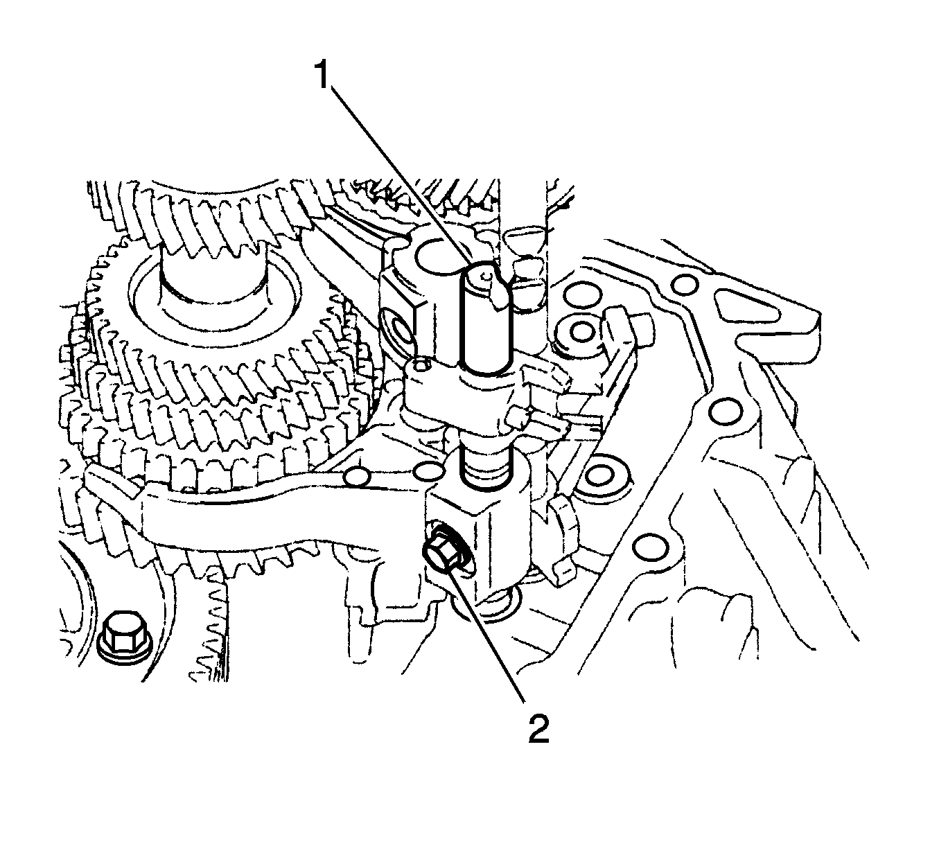
- Remove the shift fork set bolt (2) and No. 1 gear shift fork shaft (1) from the No. 1
gear shift fork.
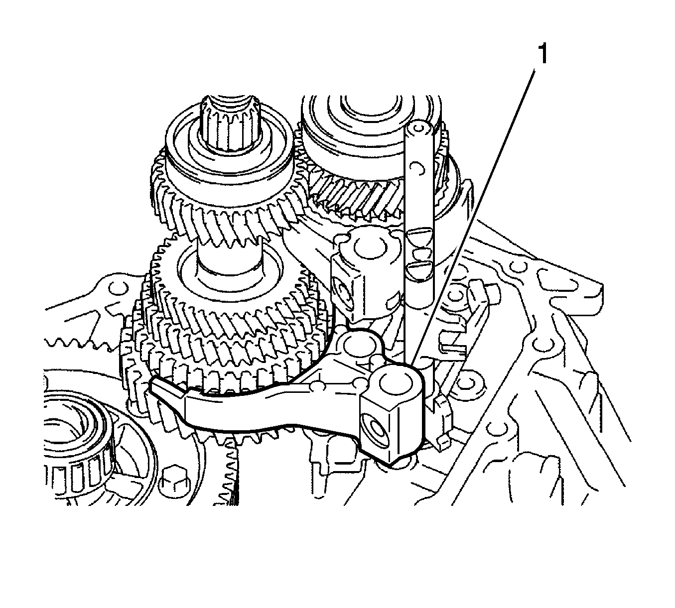
- Remove the No. 1 gear shift fork (1).
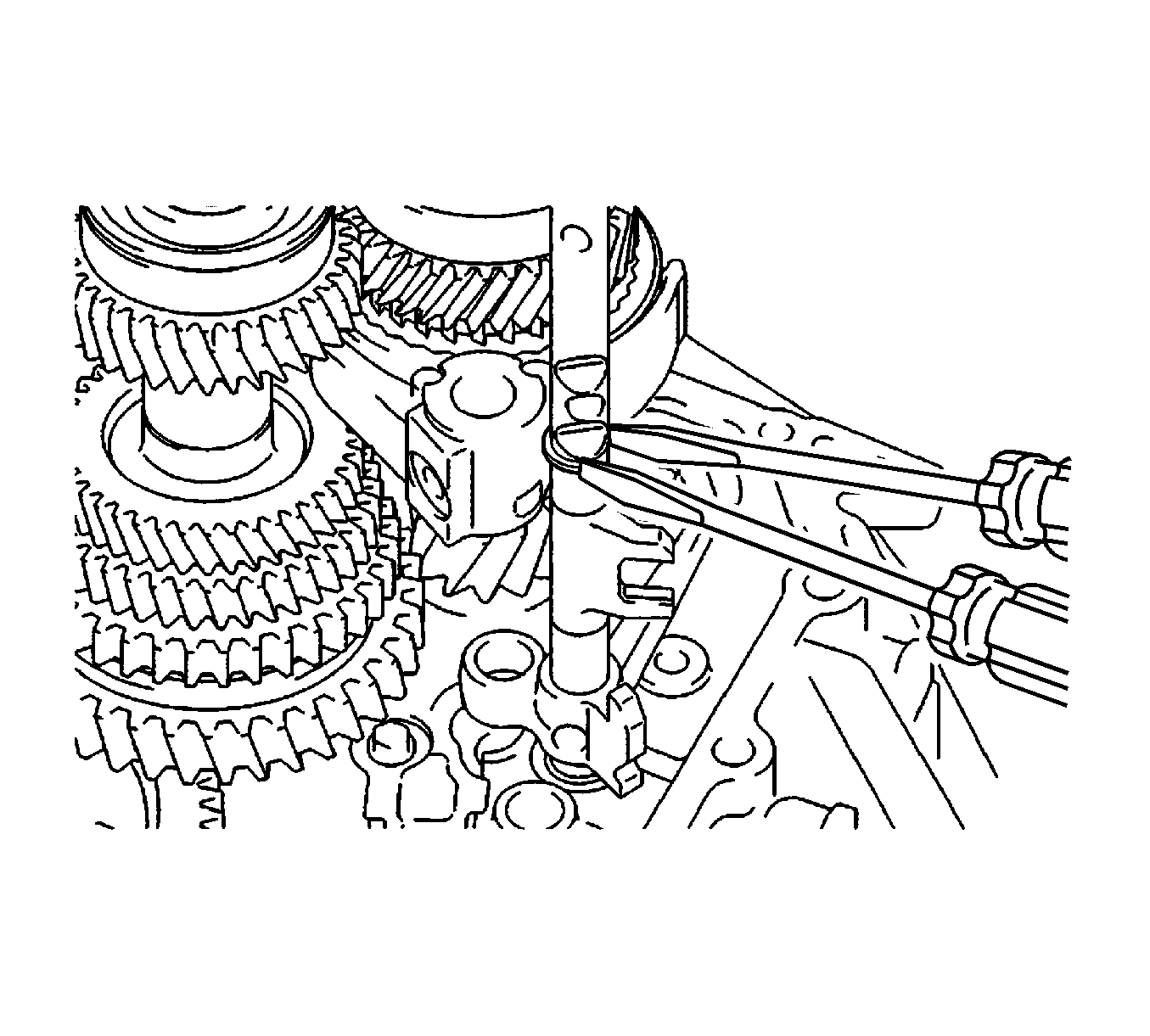
Note: Use a shop rag or piece of cloth to keep the snap ring from flying off.
- Using 2 screwdrivers and a hammer, tap out the snap ring from the No. 3 gear shift fork shaft.
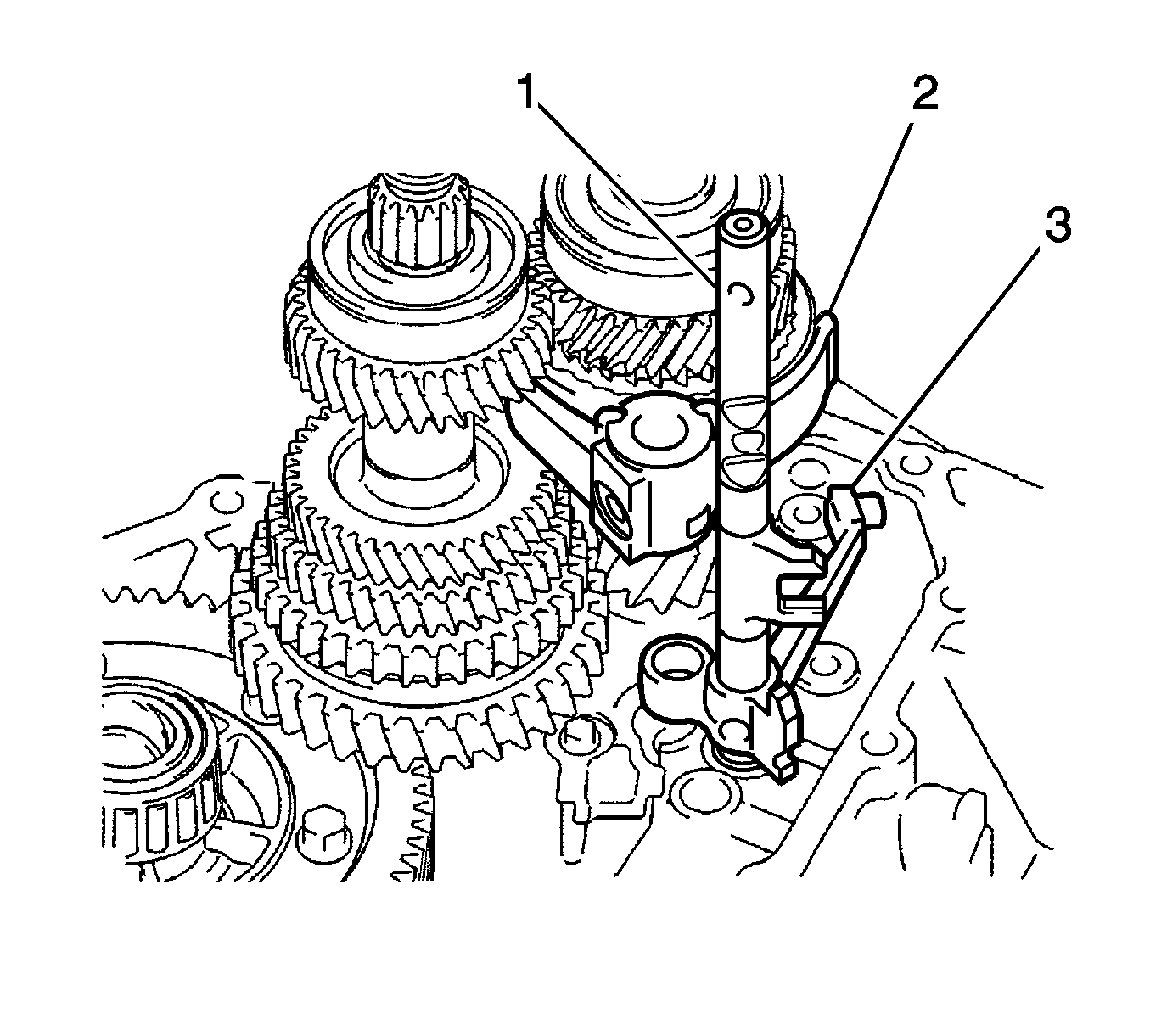
- Remove the No. 3 gear shift fork shaft (1) together with the reverse shift fork and No. 2 gear
shift fork from the manual transaxle case.
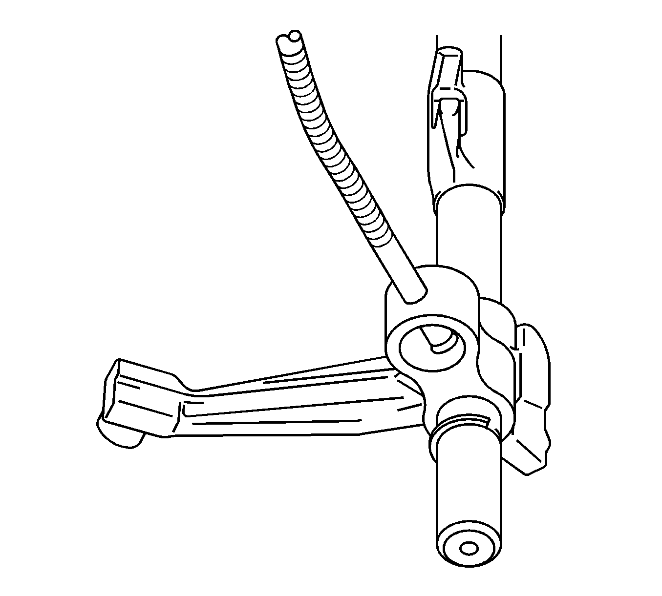
- Using a magnetic pick-up tool, remove the reverse shift fork balls from the reverse shift fork.
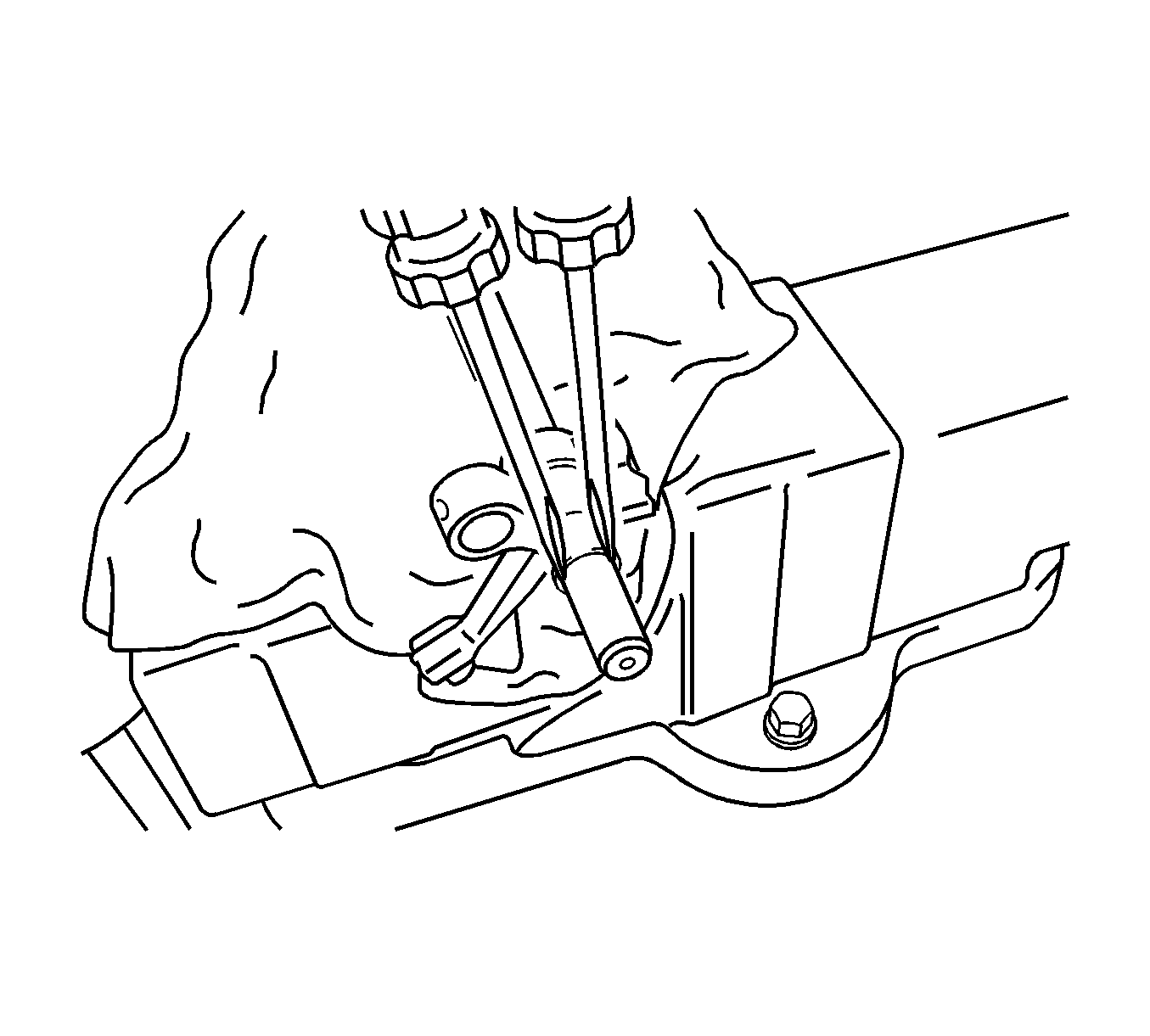
Note: Use a shop rag or piece of cloth to keep the snap ring from flying off.
- Using 2 screwdrivers and a hammer, tap the snap ring out of the No. 3 shift fork shaft.
- Remove the reverse shift fork from the No. 3 gear shift fork shaft.
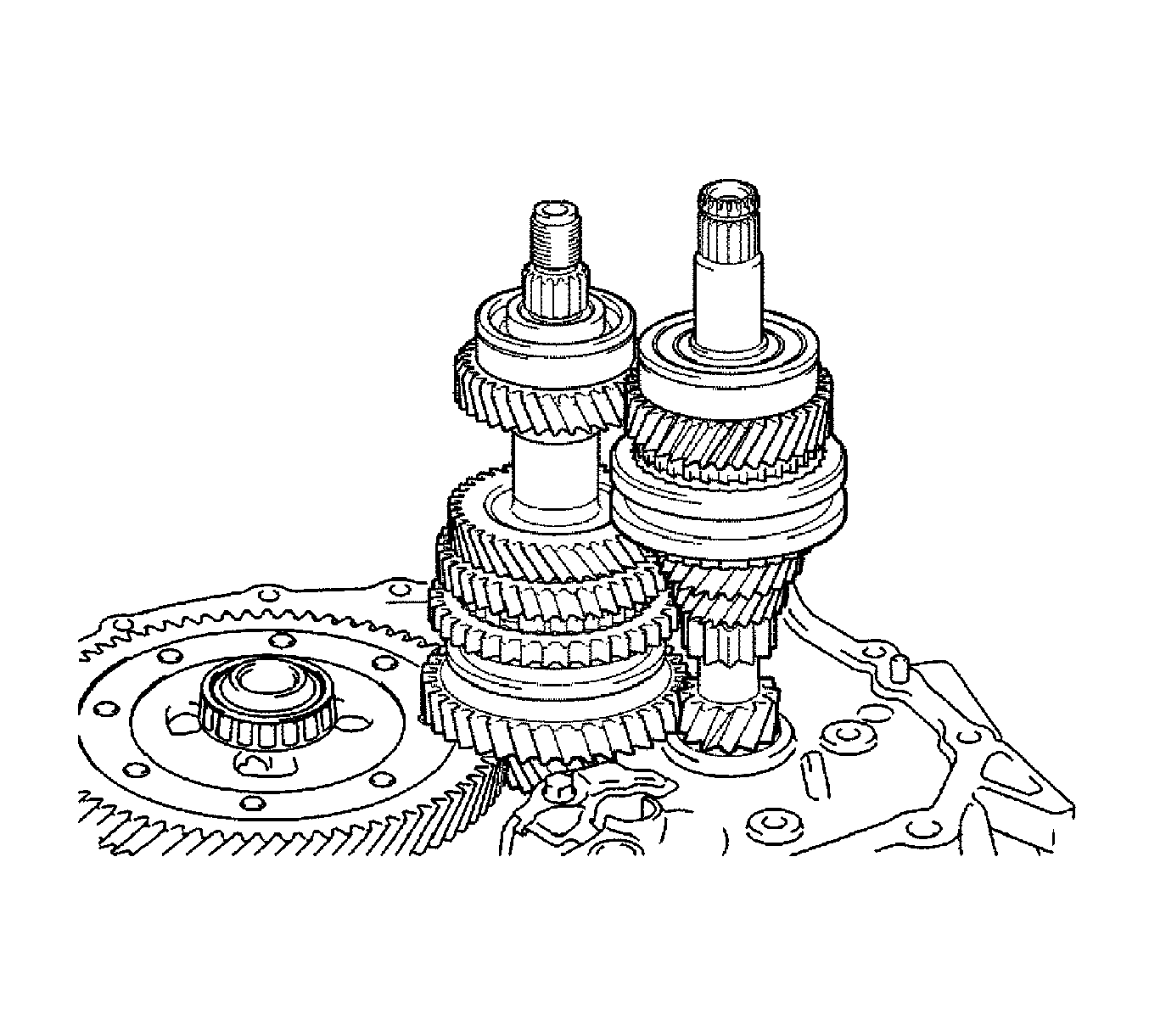
- Remove the input shaft assembly and output shaft assembly from the transaxle case.
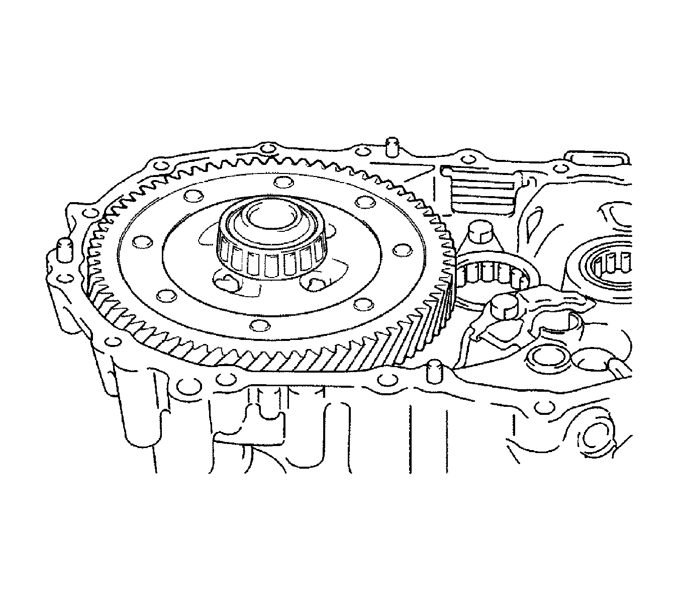
- Remove the differential case assembly from the transaxle case.
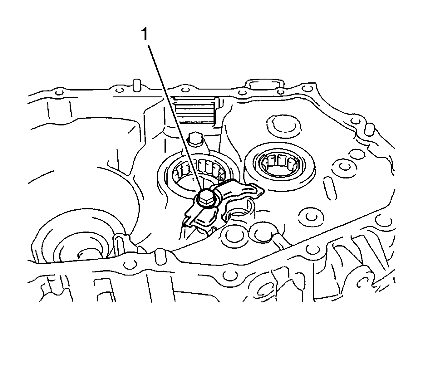
- Remove the bolt (1) and manual transaxle case receiver from the transaxle case.
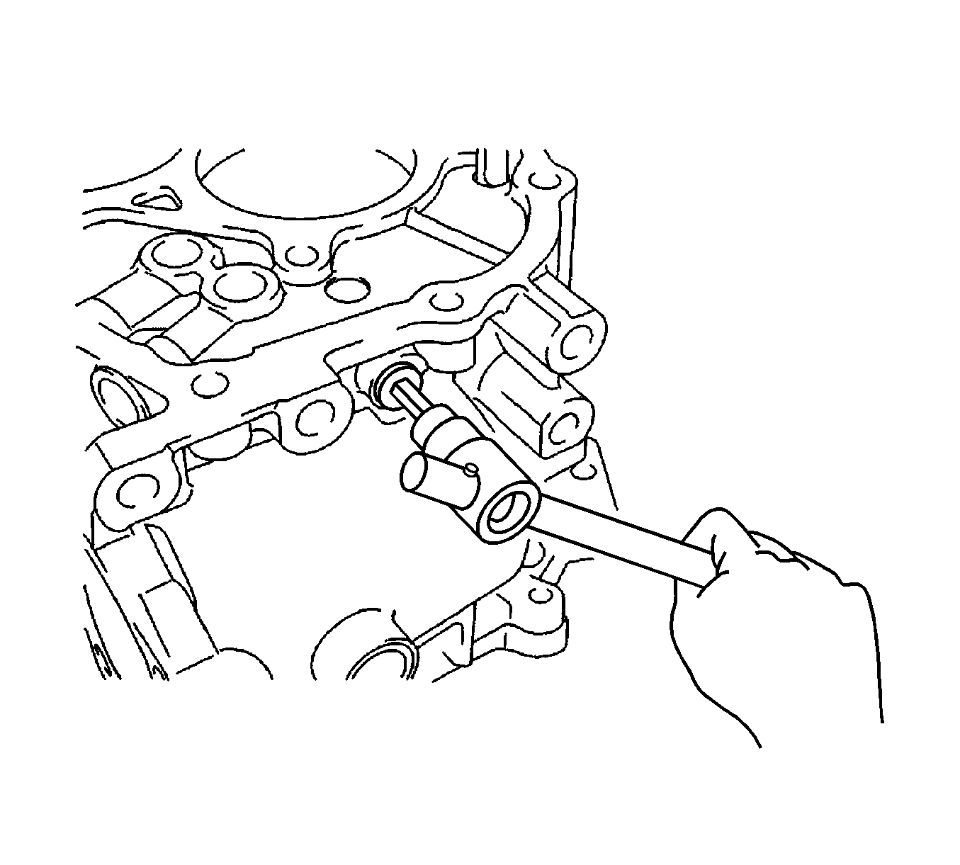
- Using a hexagon wrench, remove the reverse restrict pin plug from the manual transmission case.
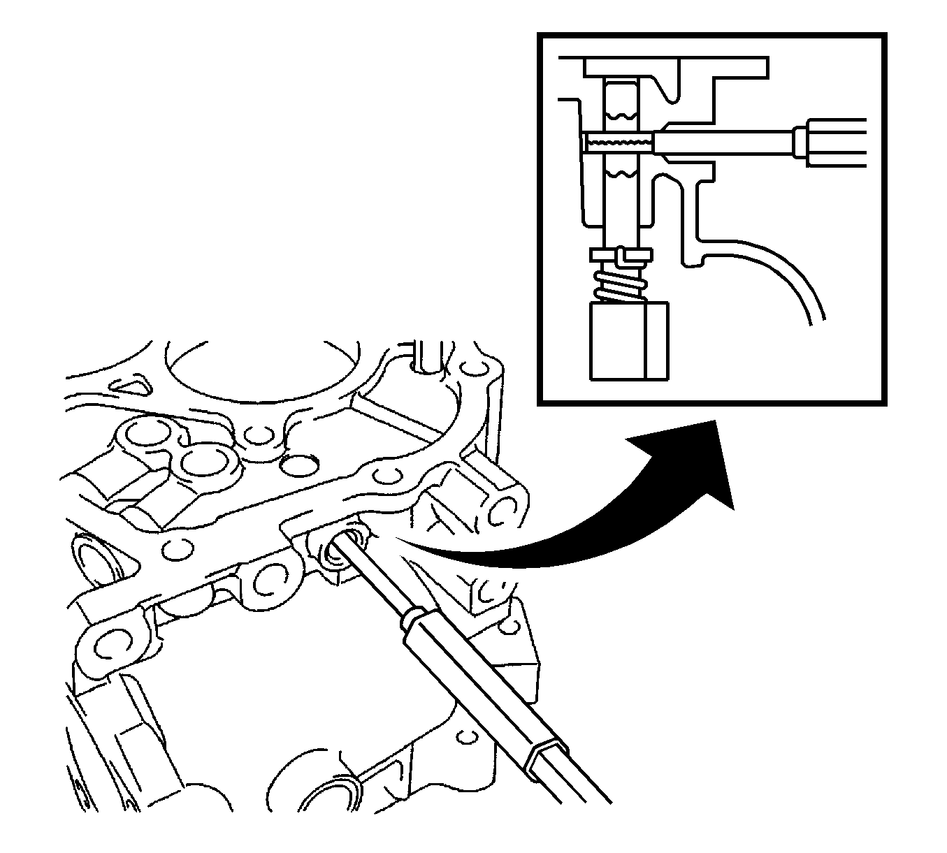
- Using a pin punch (5 mm) and a hammer, drive out the slotted spring pin and remove the reverse restrict pin assembly from
the manual transmission case.
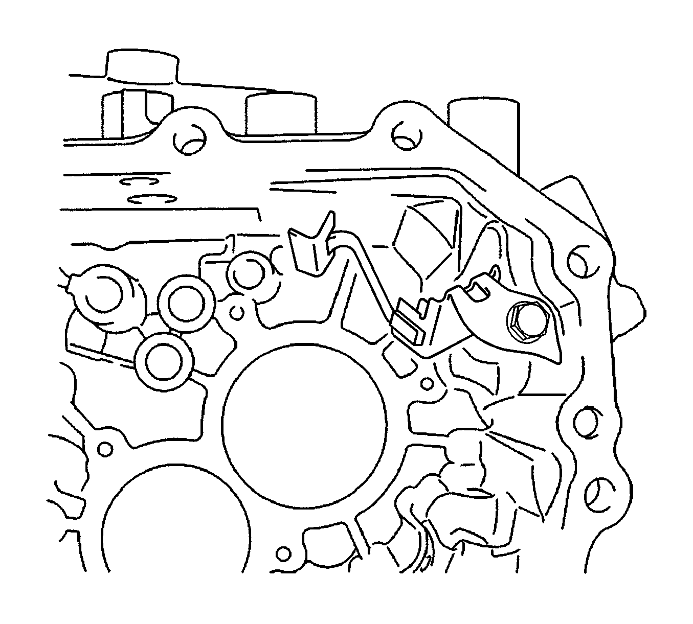
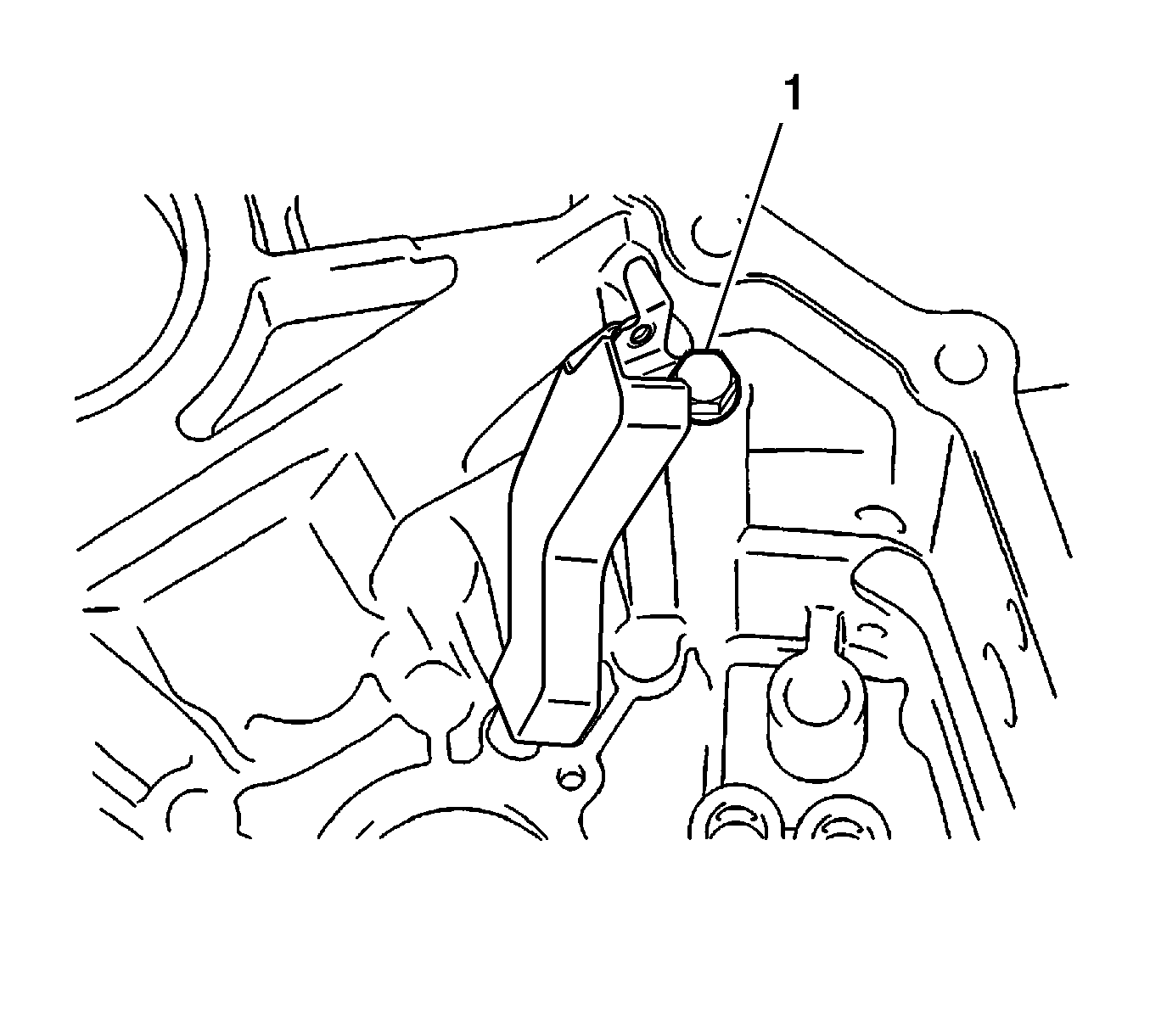
Note: Do not damage the No. 1 oil receiver pipe.
- Remove the bolt and No. 1 oil receiver pipe from the manual transmission case.
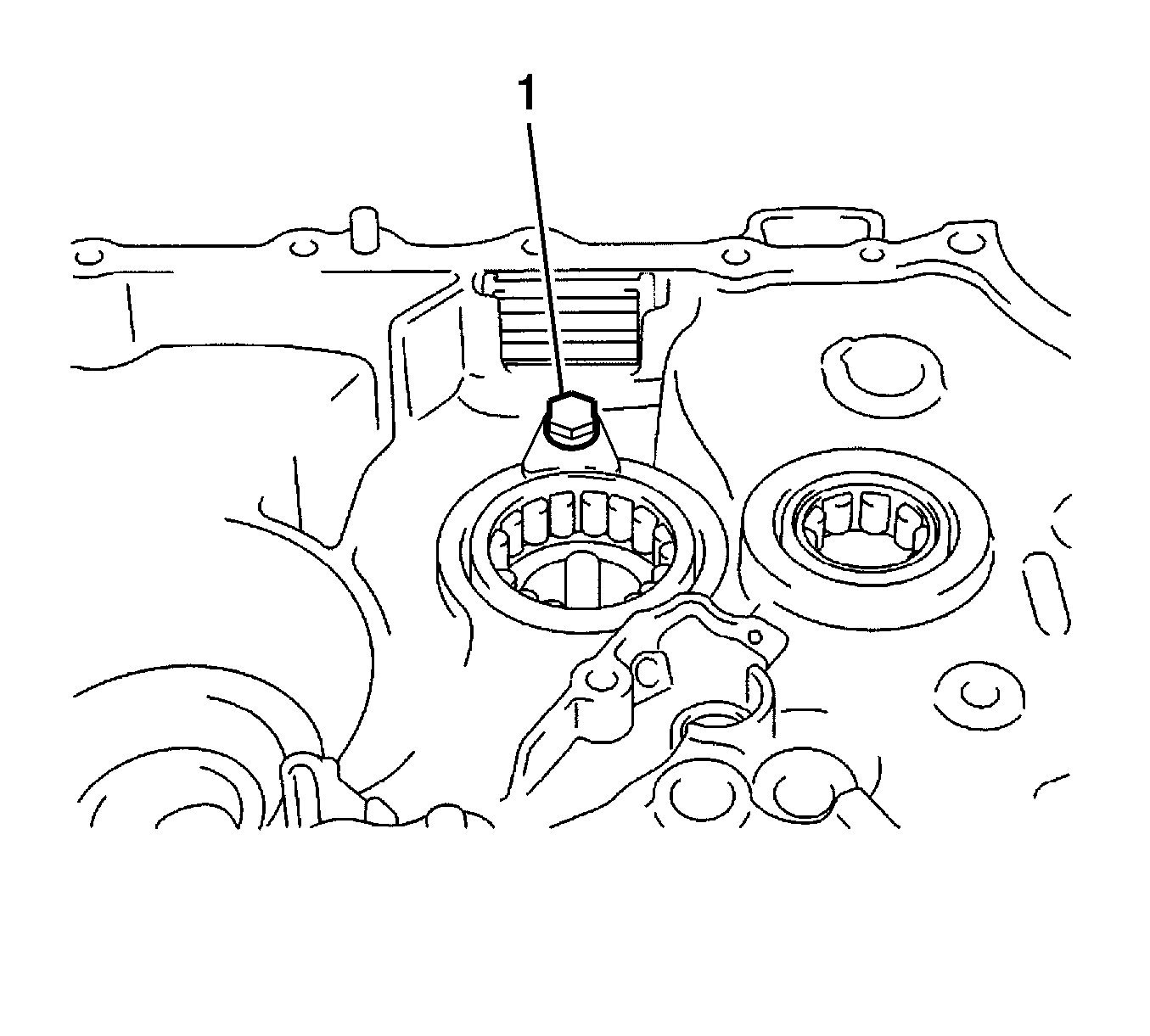
Note: Do not damage the No. 2 oil receiver pipe.
- Remove the bolt (1) and No. 2 oil receiver pipe from the manual transmission case.
- Remove the bolt (1) and bearing lock plate from the transaxle case.
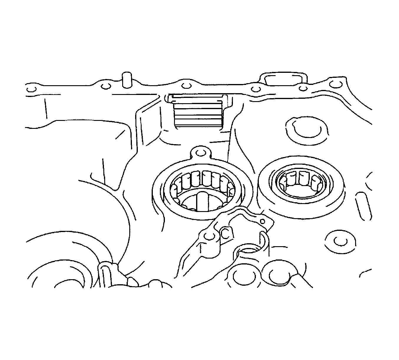
- Remove the transmission magnet from the transaxle case.
- Remove the input shaft front bearing from the transaxle case.
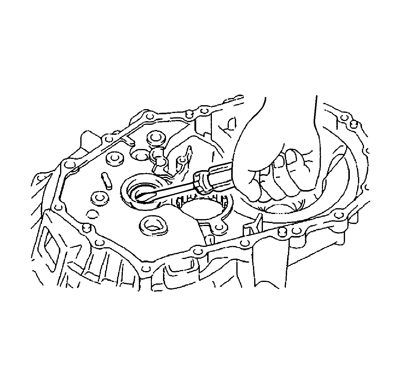
- Using a screwdriver, remove the front transaxle case oil seal from the transaxle case.
- Remove the output shaft front bearing from the transaxle case.
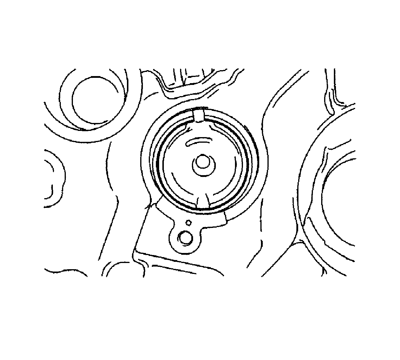
- Remove the output shaft cover from the transaxle case.
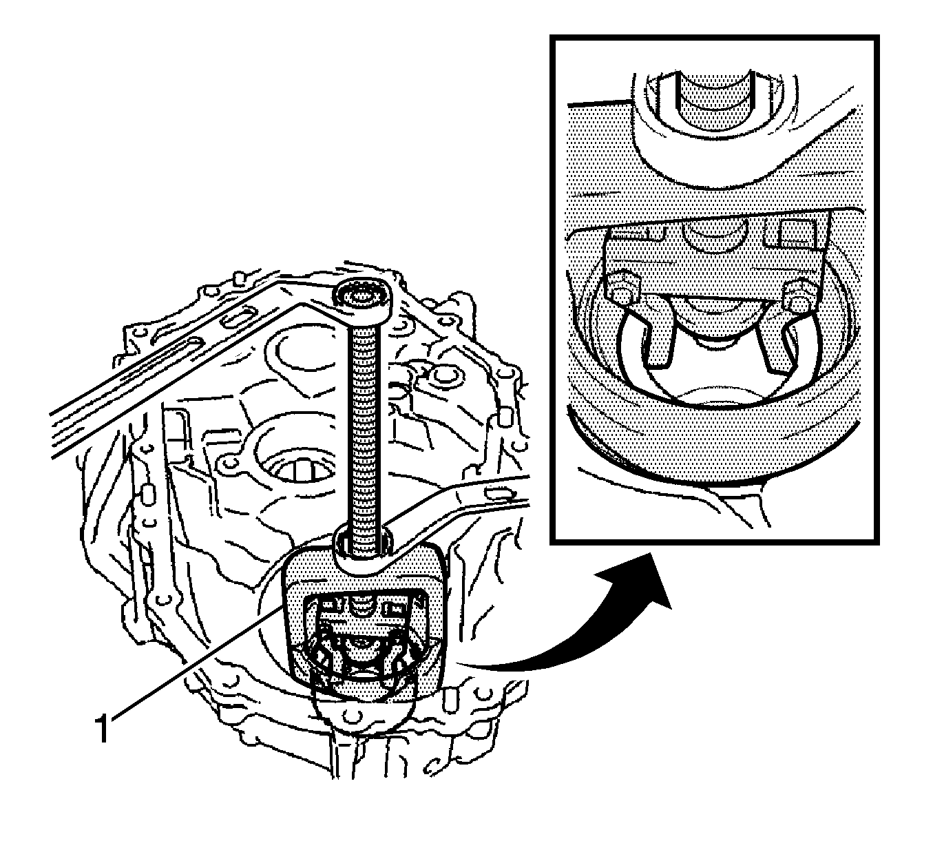
- Using a suitable puller (1), remove the front differential case front tapered roller bearing (outer
race) and plate washer from the transaxle case.
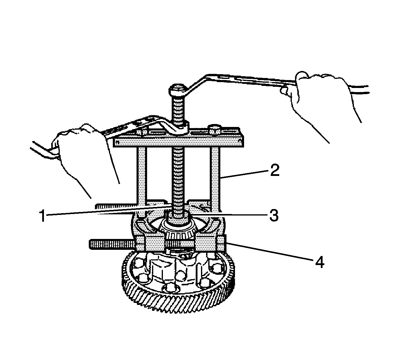
- Using a suitable puller (4), remove the front differential case front tapered roller bearing (inner
race) from the differential case assembly.
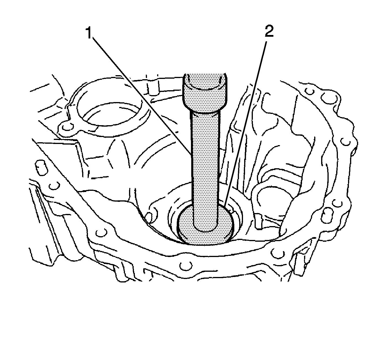
- Using a suitable driver (1) and a hammer, remove the transaxle case oil seal from the transaxle case.
- Remove the front differential case rear tapered roller bearing (outer race) and plate washer from the transmission case.
- Remove the front differential case rear tapered roller bearing (inner race) from the front differential case.
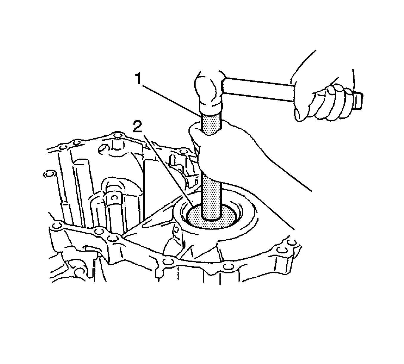
- Using a suitable driver (2) and a hammer, drive out the transmission case oil seal from the manual
transmission case.
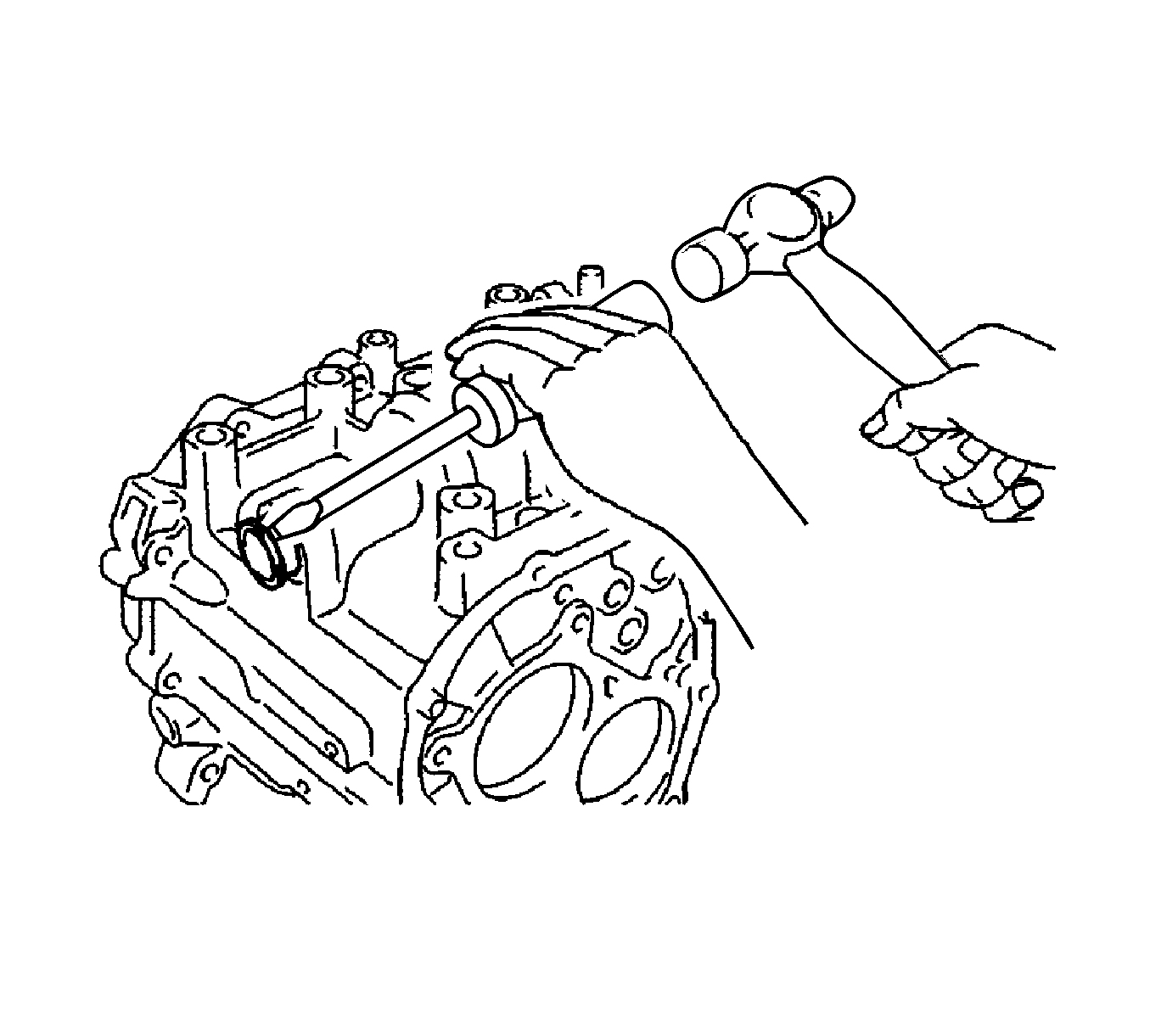
- Using a screwdriver and a hammer, remove the shift and select lever shaft oil seal.
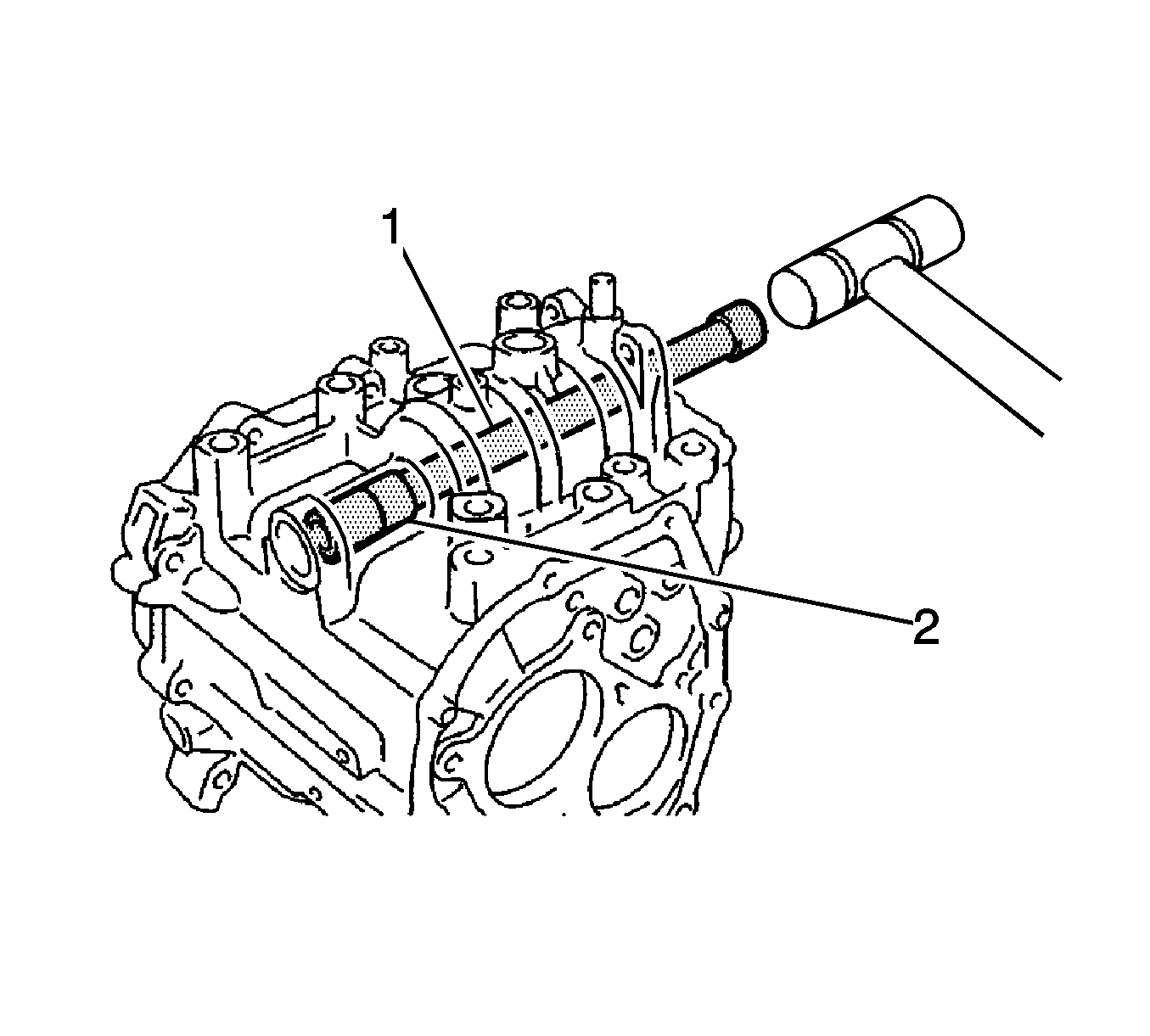
- Using a suitable driver (1) and a plastic hammer, remove the shift and select lever shaft slide ball
bearing.
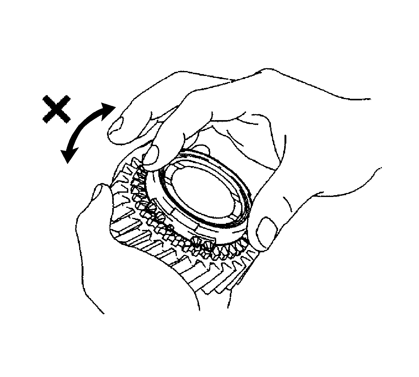
- Inspect the No. 3 synchronizer ring. Check for wear and damage.
- Coat the 5th gear cone with gear oil.
- Turn the synchronizer ring in one direction while pushing it against the 5th gear cone.
- Check that the ring locks.
If the synchronizer ring does not lock, replace the synchronizer ring.
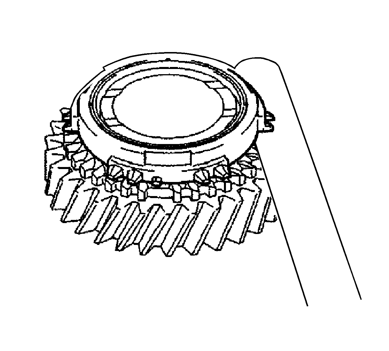
- Using a feeler gage, measure the clearance between the synchronizer ring and the gear spline end.
Specifications
| • | Standard clearance - 0.75-1.65 mm (0.0295-0.0249 in) |
| • | Maximum clearance - 0.75 mm (0.0295 in) |
- If the clearance is less than the minimum, replace the synchronizer ring.
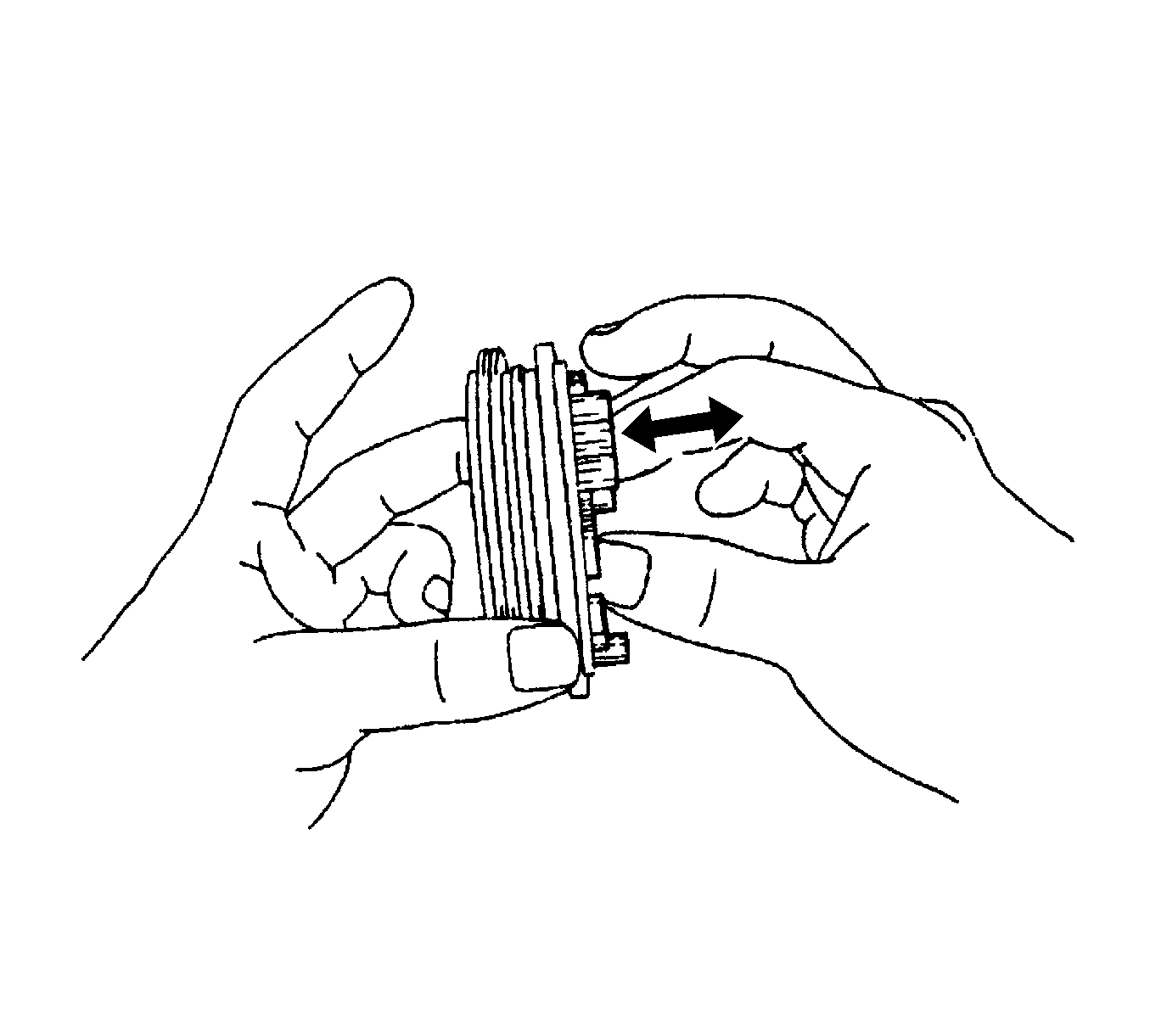
- Check the sliding condition between the No. 3 transmission hub sleeve and the No. 3 transmission clutch hub.
- Check that the edges of the No. 3 transmission hub sleeve spline gear are not worn down.
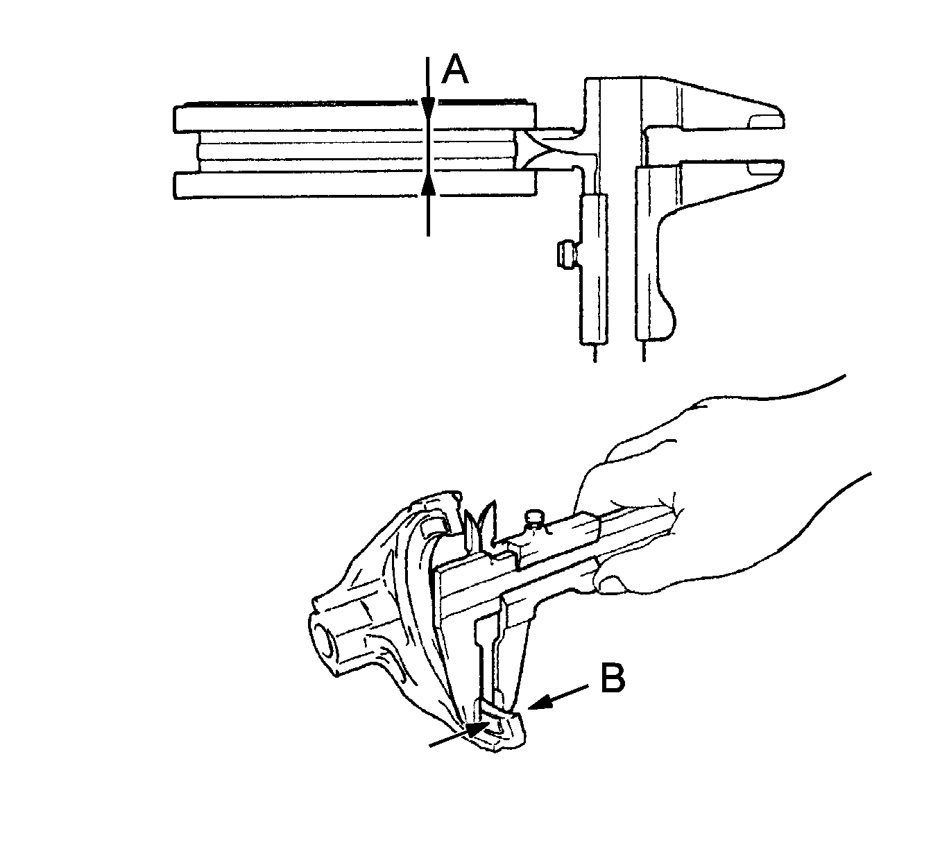
- Using vernier calipers, measure the width of the No. 3 transmission hub sleeve groove (A) and
the thickness of the claw part on the No. 3 gear shift fork (B), and calculate the clearance.
Specification
Standard Clearance (A-B) 0.3-0.5 mm (0.0118-0.0197 in)
- If the clearance exceeds the standard, replace the No. 3 transmission hub sleeve and No. 3 gear shift fork.
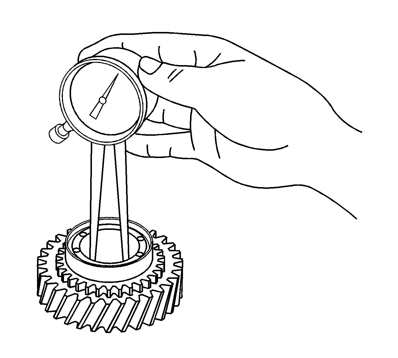
- Inspect the 5th gear. Using a caliper gage, measure the inside diameter.
Specifications
| • | Standard inside diameter - 29.915-29.931 mm (1.1778-1.1783 in) |
| • | Maximum inside diameter - 29.931 mm (1.1783 in) |
- If the inside diameter exceeds the maximum, replace the 5th gear.
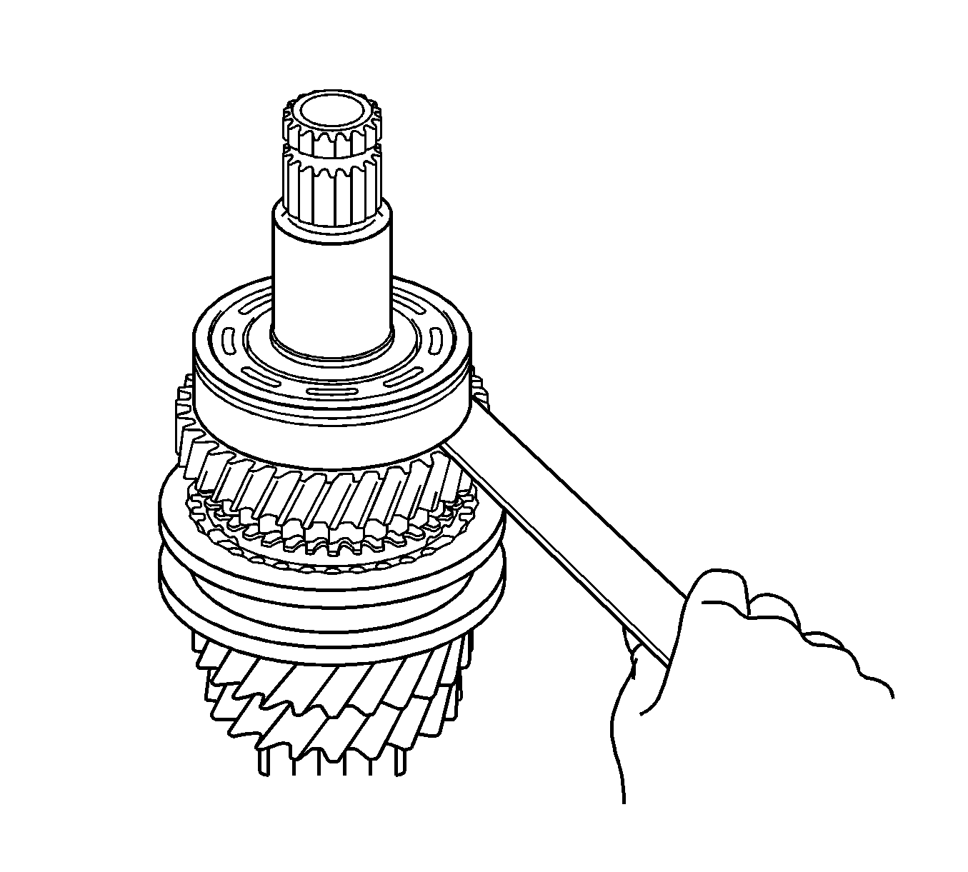
- Using a feeler gage, measure the 4th gear thrust clearance.
Specifications
| • | Standard clearance - 0.10-0.55 mm (0.0039-0.0217 in) |
| • | Maximum clearance - 0.55 mm (0.0217 in) |
- If the clearance exceeds the maximum, replace the No. 2 transmission clutch hub, 4th gear or input shaft rear radial ball bearing.
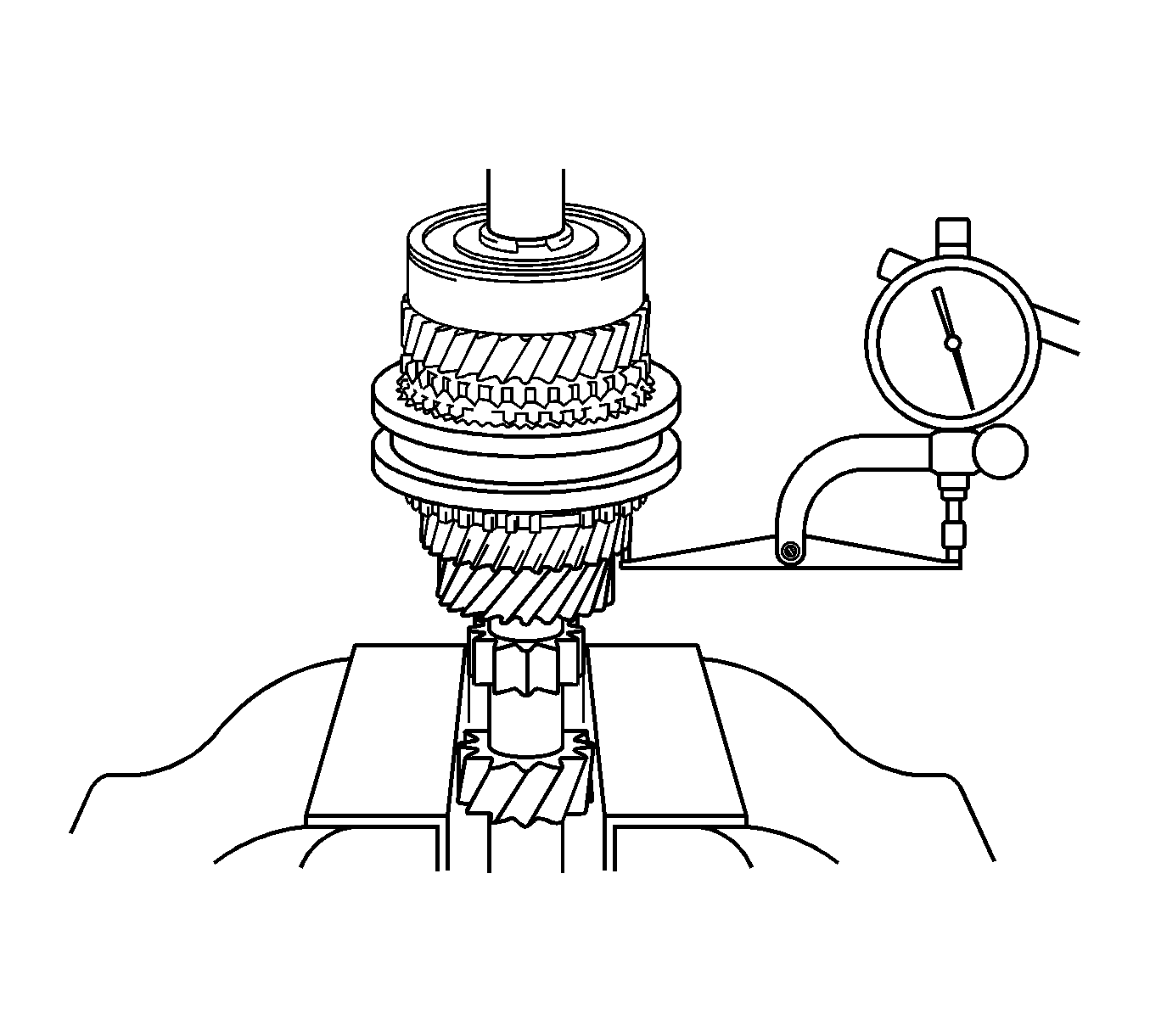
- Using a dial indicator, measure the 3rd gear thrust clearance.
Specifications
| • | Standard clearance - 0.10-0.35 mm (0.0039-0.0138 in) |
| • | Maximum clearance - 0.35 mm (0.0138 in) |
- If the clearance exceeds the maximum, replace the No. 2 transmission clutch hub, 3rd gear or input shaft.
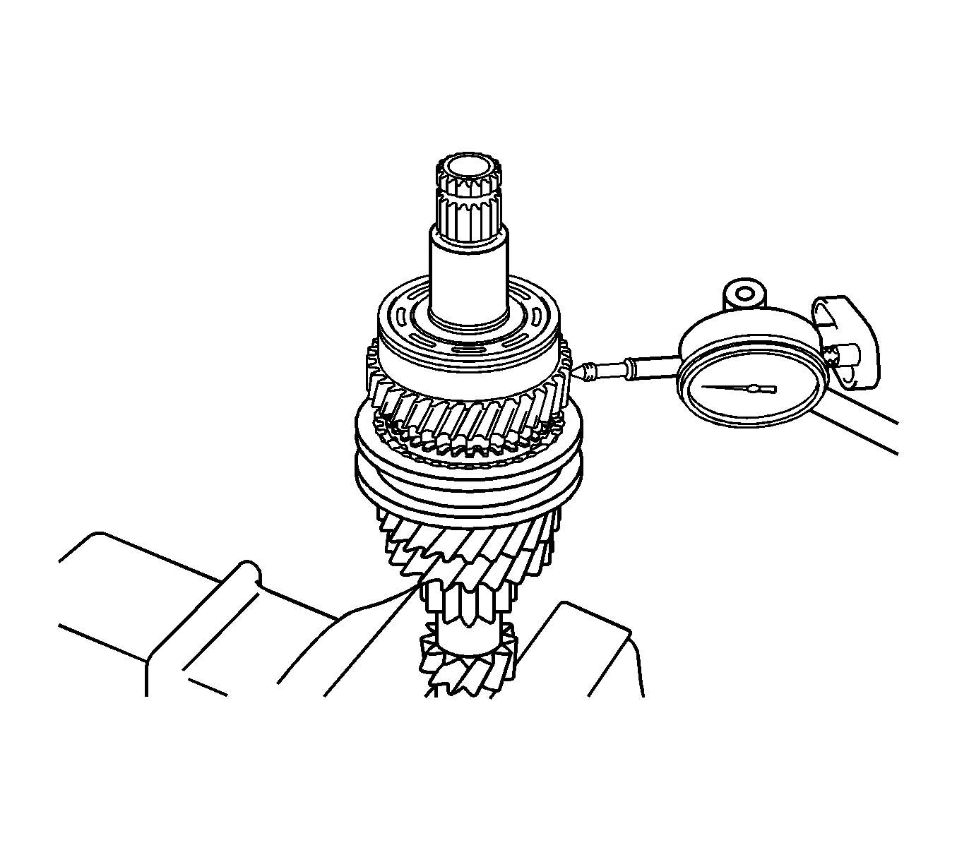
- Using a dial indicator, measure the 4th gear radial clearance between the gear and shaft.
Specifications
| • | Standard clearance, NSK made bearing - 0.009-0.050 mm (0.0003-0.0019 in) |
| • | Standard clearance, KOYO made bearing - 0.009-0.050 mm (0.0003-0.0019 in) |
| • | Maximum clearance, NSK made bearing - 0.050 mm (0.0019 in) |
| • | Maximum clearance, KOYO made bearing - 0.050 mm (0.0019 in) |
- If the clearance exceeds the maximum, replace the 4th gear, 4th gear needle roller bearing or input shaft.
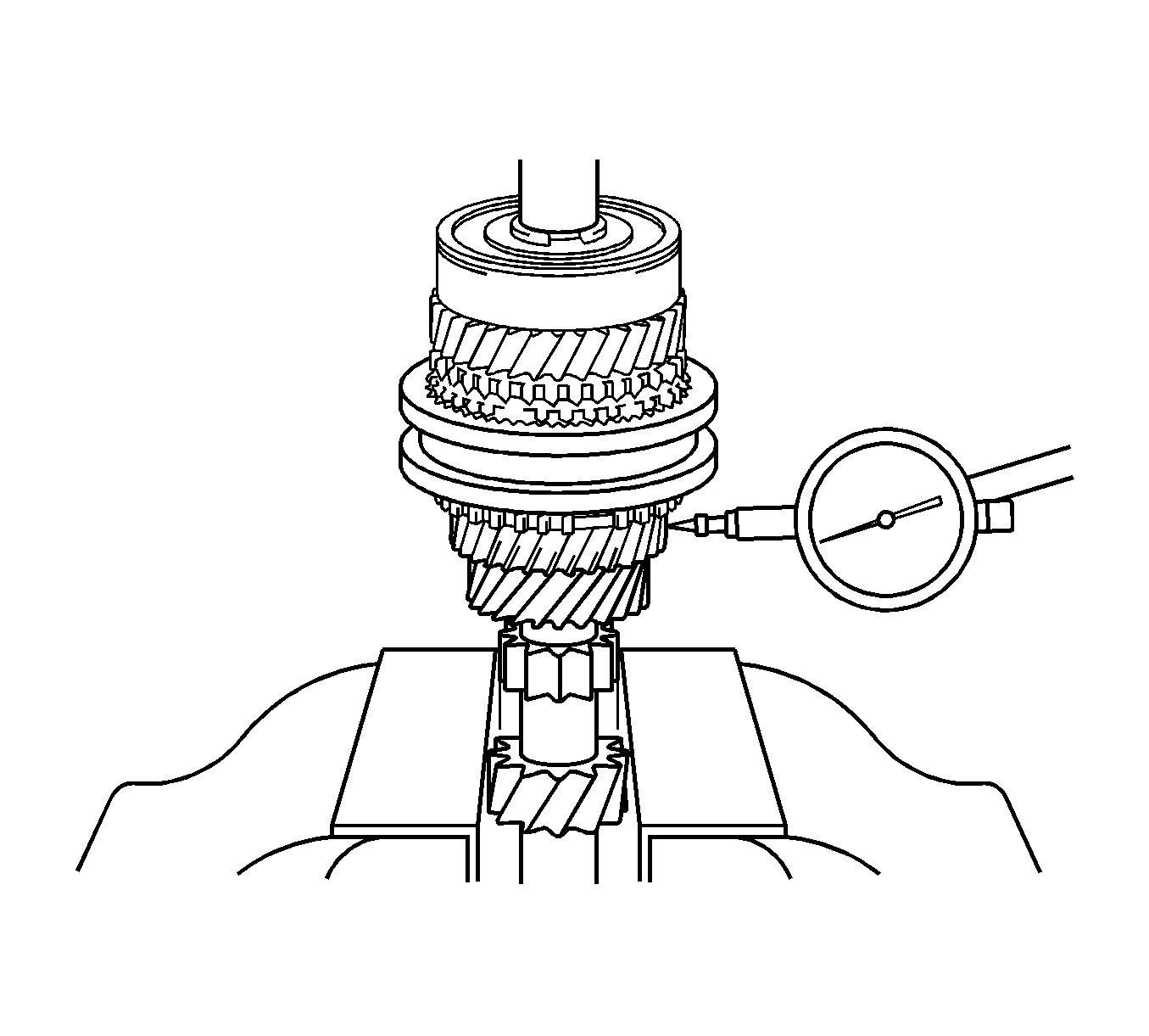
- Using a dial indicator, measure the 3rd gear radial clearance.
Specifications
| • | Standard clearance, NSK made bearing - 0.015-0.056 mm (0.0005-0.0022 in) |
| • | Standard clearance, KOYO made bearing - 0.015-0.058 mm (0.0005-0.0022 in) |
| • | Maximum clearance, NSK made bearing - 0.056 mm (0.0022 in) |
| • | Maximum clearance, KOYO made bearing - 0.058 mm (0.0022 in) |
- If the clearance exceeds the maximum, replace the 3rd gear, 3rd gear needle roller bearing or input shaft.
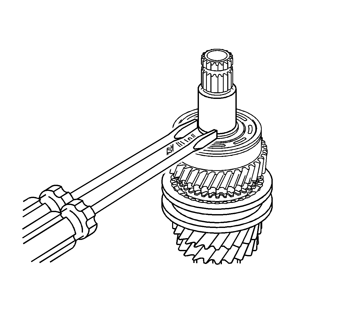
Note: Use a shop rag or piece of cloth to keep the snap ring from flying off.
- Using 2 screwdrivers and a hammer, remove the input shaft rear bearing shaft snap ring from the input shaft.
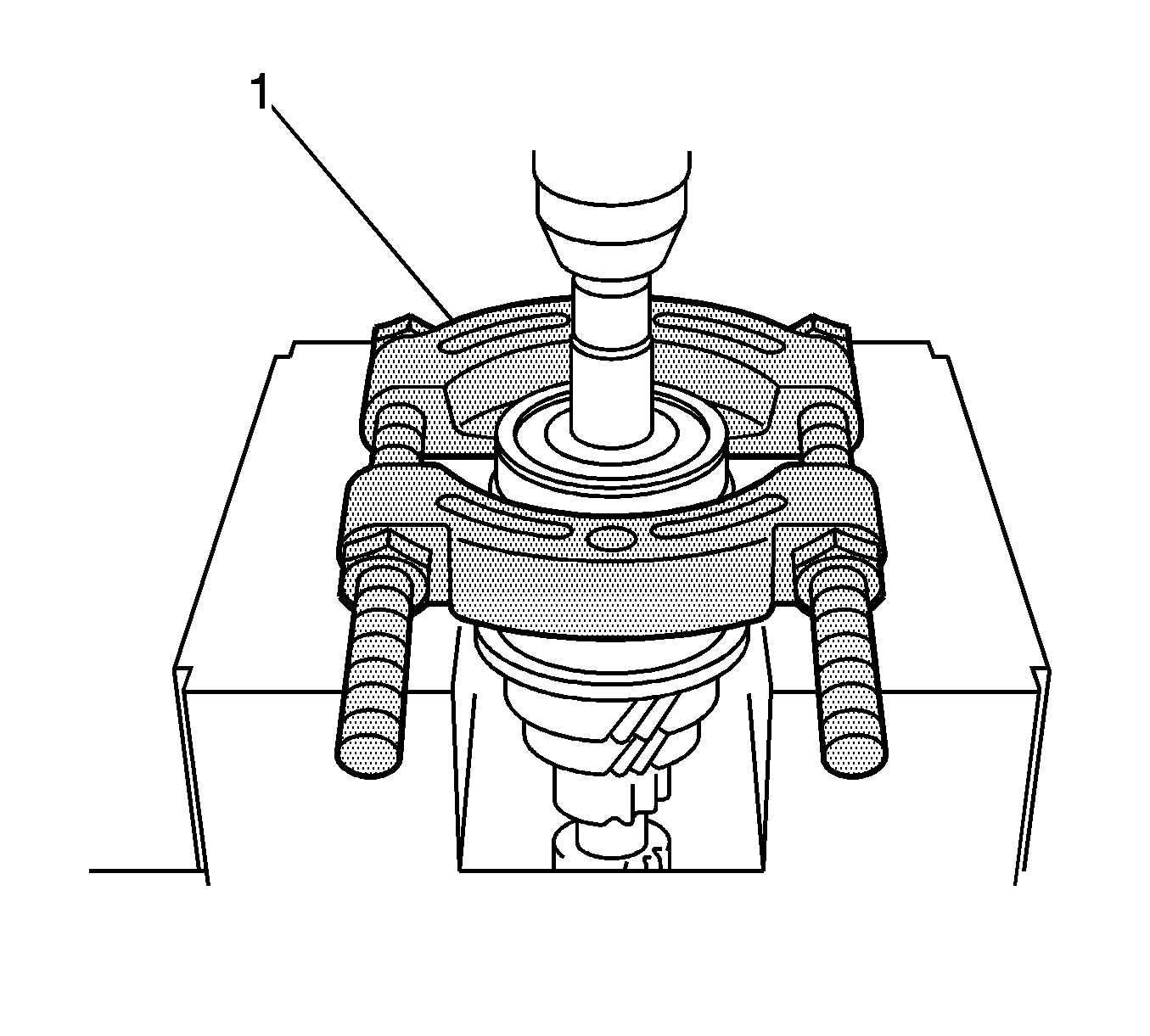
Note: Support the input shaft assembly by hand to prevent it from dropping off.
- Using a press (1), remove the input shaft rear radial ball bearing and 4th gear from the input shaft.
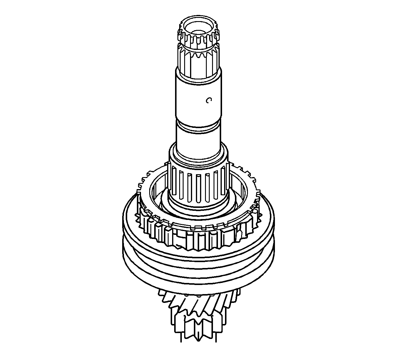
- Remove the 4th gear needle roller bearing and 4th gear bearing spacer from the input shaft.
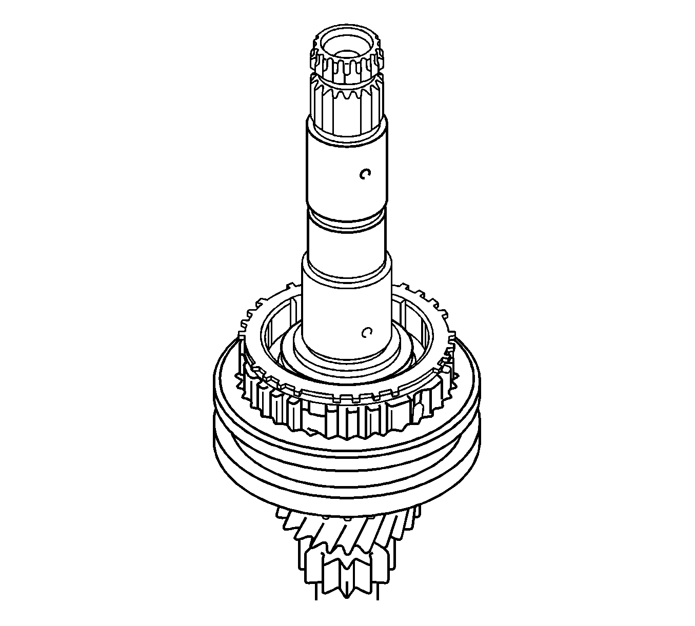
- Remove the 4th gear synchronizer ring from the No. 2 transmission clutch hub.
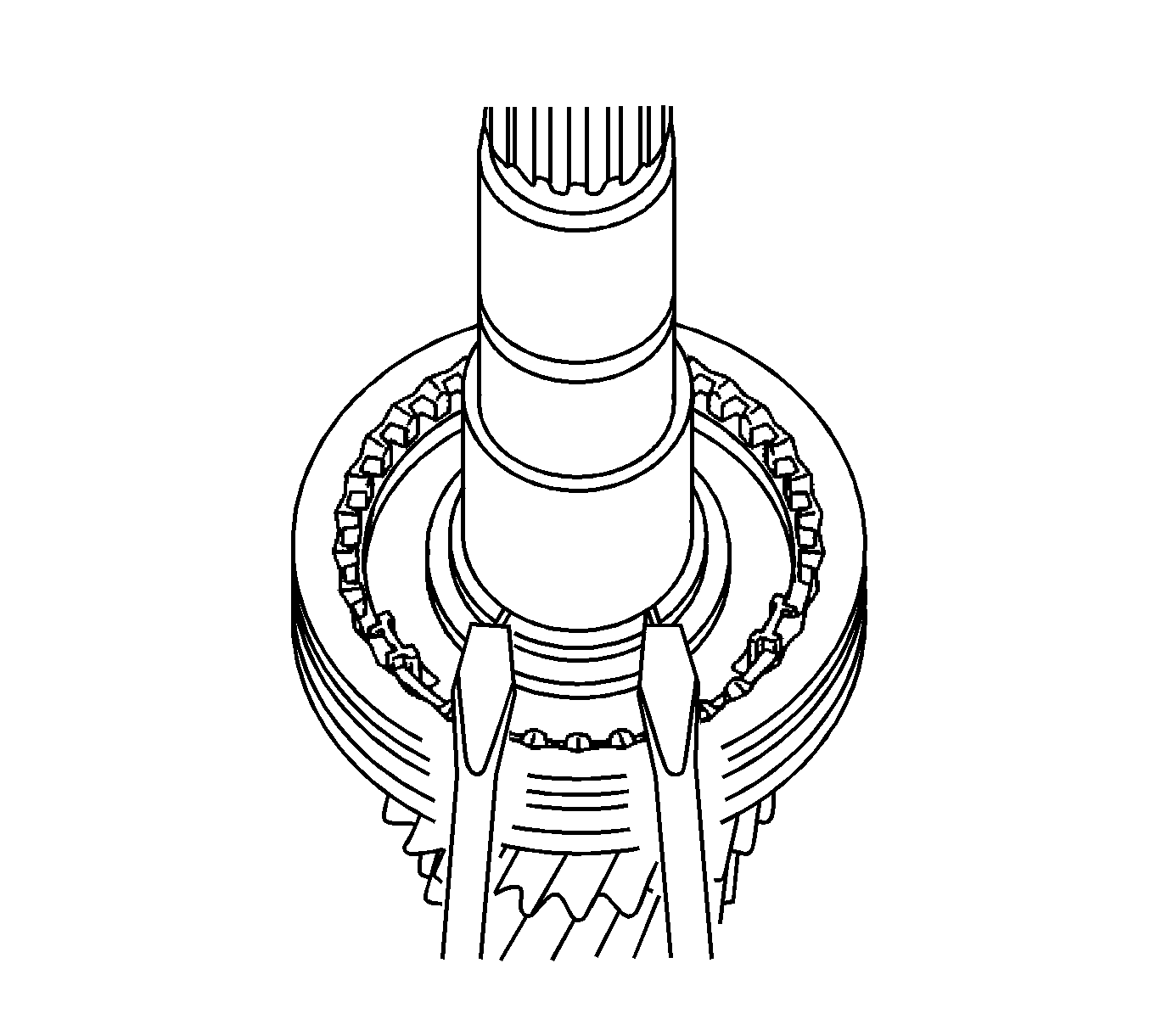
Note: Use a shop rag or piece of cloth to keep the snap ring from flying off.
- Using 2 screwdrivers and a hammer, remove the No. 2 clutch hub setting shaft snap ring from the input shaft.
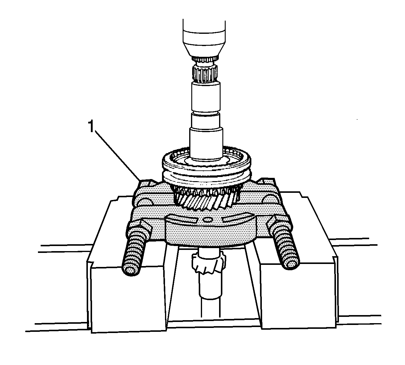
Note: Support the input shaft assembly by hand to prevent it from dropping off.
- Using a press (1), remove the No. 2 transmission clutch hub and 3rd gear from the input shaft.
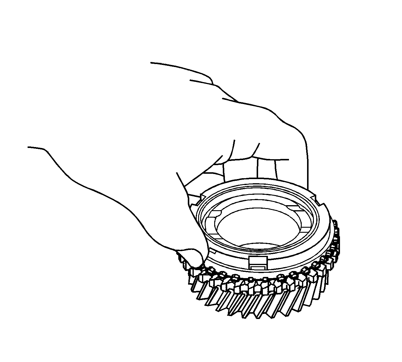
- Remove the 3rd gear synchronizer ring from the 3rd gear.
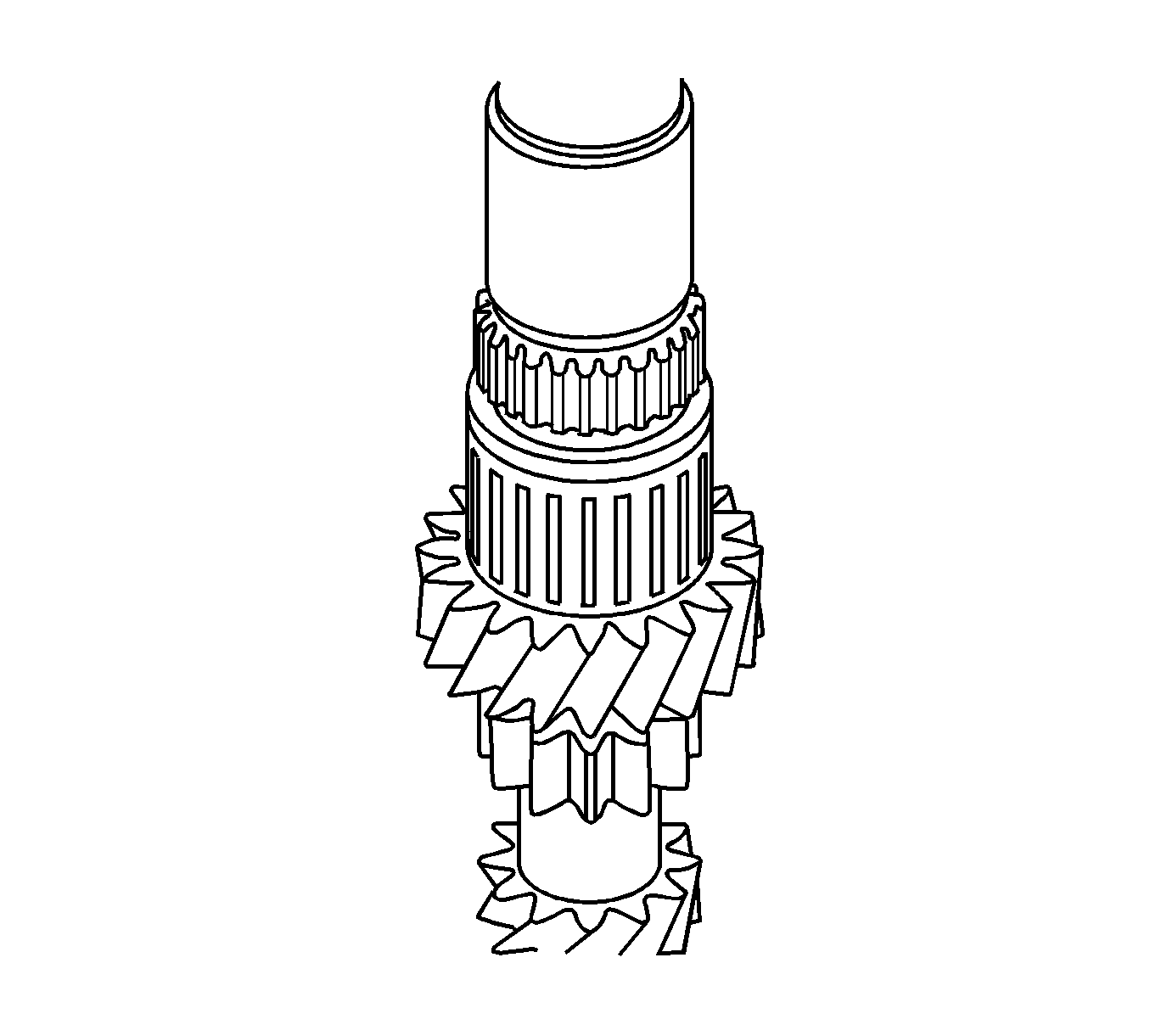
- Remove the 3rd gear needle roller bearing from the input shaft.
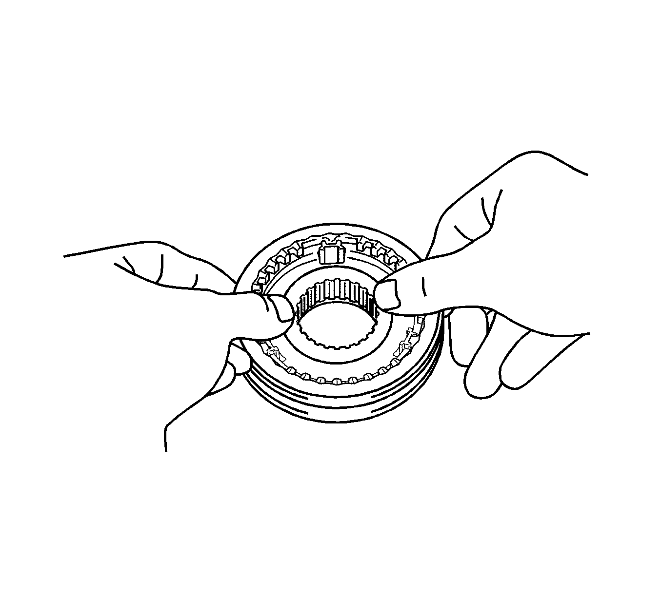
Note: Use a shop rag or piece of cloth to keep the shifting keys and shifting key springs from flying off.
- Remove the No. 2 transmission hub sleeve, shifting keys, and shifting key springs from the No. 2 transmission clutch hub.
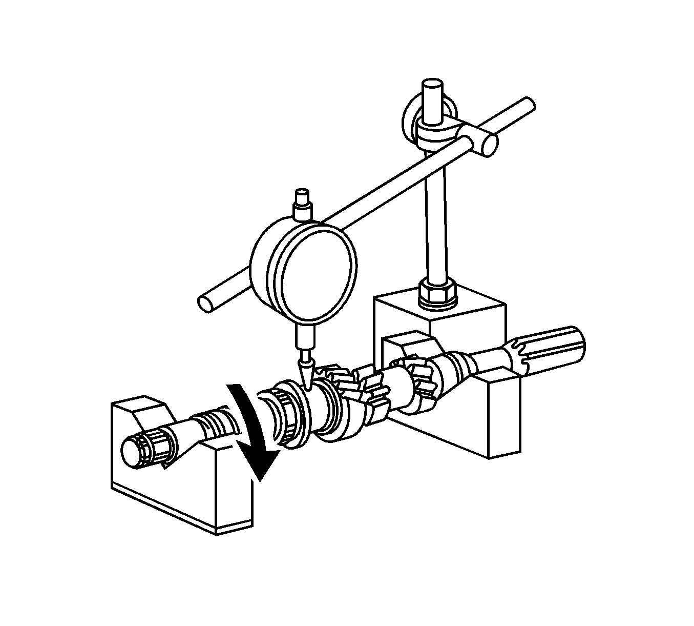
- Using a dial indicator, check the input shaft runout.
Specification
Maximum runout - 0.015 mm (0.0005 in)
- If the runout exceeds the maximum, replace the input shaft.
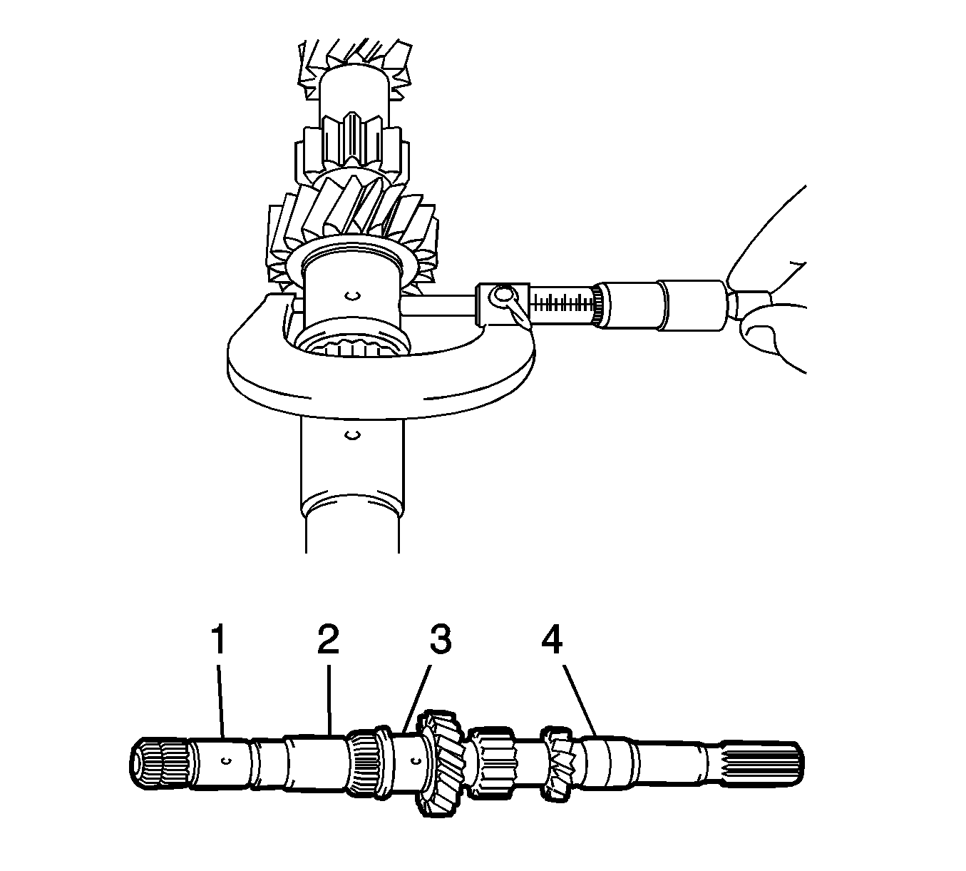
- Using a micrometer, measure the outer diameter of the input shaft journal surface at the locations indicated.
Standard Outer Diameter
| • | Part 1 - 24.885-24.900 mm (0.9797-0.9803 in) |
| • | Part 2 - 28.991-29.006 mm (1.1414-1.1420 in) |
| • | Part 3 - 30.985-31.000 mm (1.2198-1.2204 in) |
| • | Part 4 - 24.985-25.000 mm (0.9836-0.9842 in) |
Minimum Outer Diameter
| • | Part 1 - 24.885 mm (0.9797 in) |
| • | Part 2 - 28.991 mm (1.1414 in) |
| • | Part 3 - 30.985 mm (1.2198 in) |
| • | Part 4 - 24.985 mm (0.9836 in) |
- If any of the outer diameters are less than the minimum, replace the input shaft.
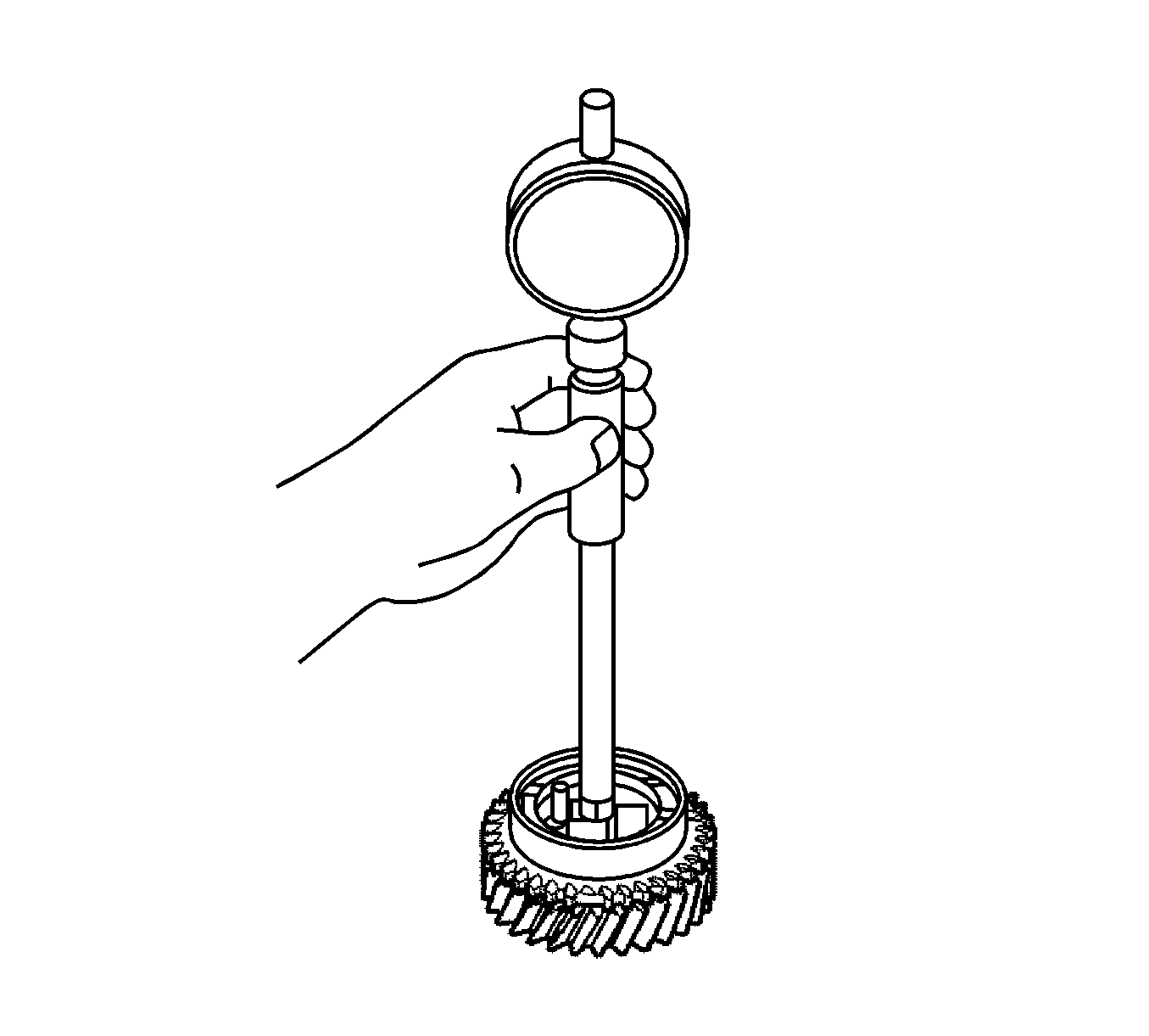
- Using a cylinder gage, measure the inside diameter of the 4th gear.
Specifications
| • | Standard Inside Diameter - 34.015-34.031 mm (1.3391-1.3398 in) |
| • | Maximum Inside Diameter - 34.031 mm (1.3398 in) |
- If the inside diameter exceeds the maximum, replace the 4th gear.
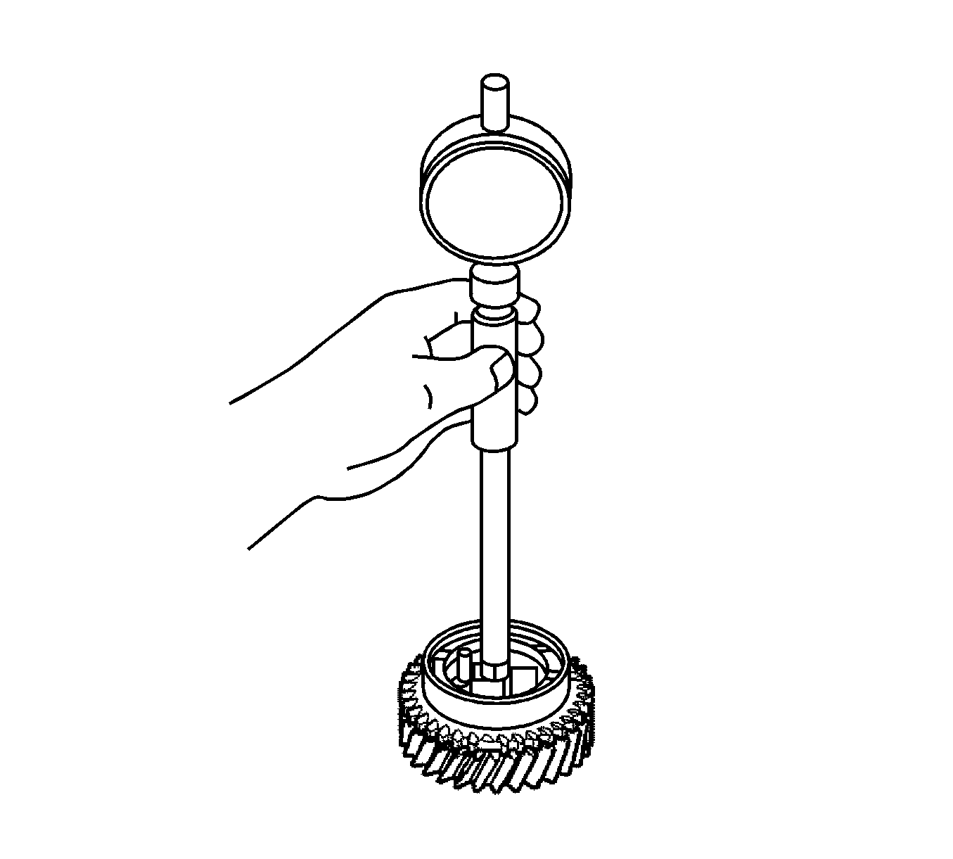
- Using a cylinder gage, measure the inside diameter of the 3rd gear.
Specifications
| • | Standard Inside Diameter - 36.015-36.031 mm (1.4179-1.4185 in) |
| • | Maximum Inside Diameter - 36.031 mm (1.4185 in) |
- If the inside diameter exceeds the maximum, replace the 3rd gear.
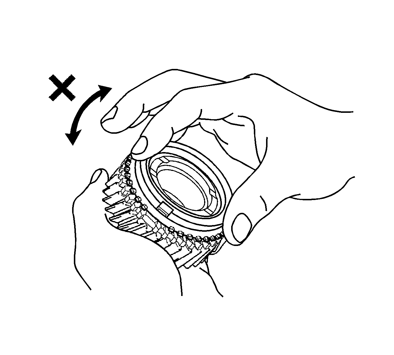
- Inspect the 4th gear synchronizer ring, check for wear and damage.
- Coat the 4th gear cone with gear oil.
- Turn the synchronizer ring in one direction while pushing it against the 4th gear cone.
- Check that the ring locks.
If the synchronizer ring does not lock, replace the synchronizer ring.
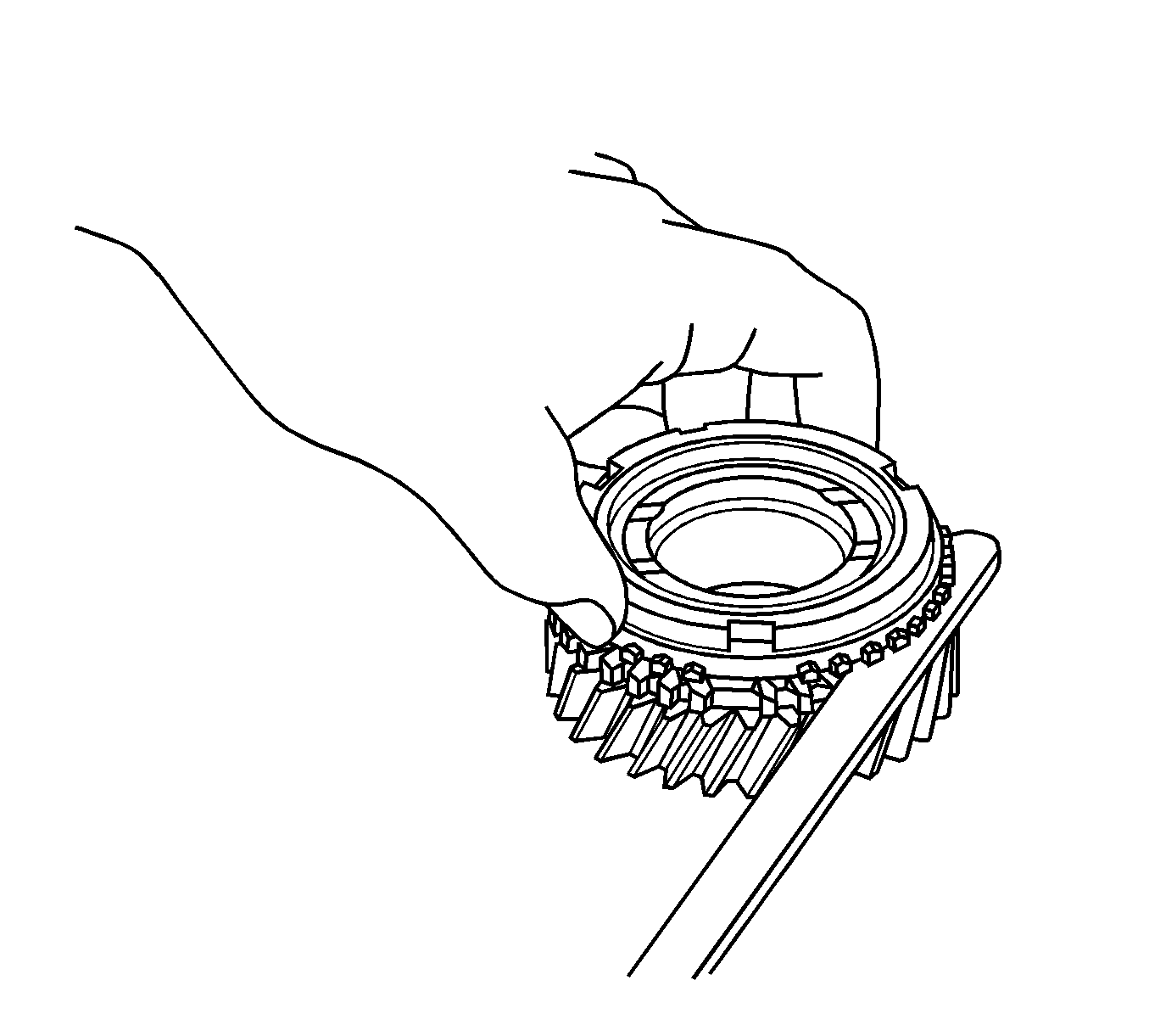
- Using a feeler gage, measure the clearance between the synchronizer ring and the gear spline end.
Specifications
| • | Standard Clearance - 0.65-1.75 mm (0.0256-0.0689 in) |
| • | Minimum Clearance - 0.65 mm (0.0256 in) |
- If the clearance is less than the minimum, replace the synchronizer ring.

- Inspect the 3rd gear synchronizer ring. Check for wear and damage.
- Coat the 3rd gear cone with gear oil.
- Turn the synchronizer ring in one direction while pushing it against the 3rd gear cone.
- Check that the ring locks.
If the synchronizer ring does not lock, replace the synchronizer ring.

- Using a feeler gage, measure the clearance between the synchronizer ring and the gear spline end.
Specifications
| • | Standard Clearance - 0.75-1.65 mm (0.0295-0.0649 in) |
| • | Minimum Clearance - 0.75 mm (0.0295 in) |
- If the clearance is less than the minimum, replace the synchronizer ring.
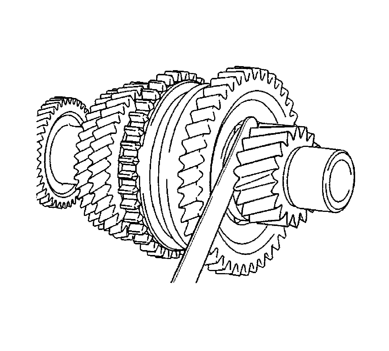
- Using a feeler gage, measure the 1st gear thrust clearance.
Specifications
| • | Standard Clearance - 0.10-0.40 mm (0.0039-0.0157 in) |
| • | Minimum Clearance - 0.40 mm (0.0157 in) |
- If the clearance exceeds the maximum, replace the 1st gear thrust washer, 1st gear or No. 1 transmission clutch hub.
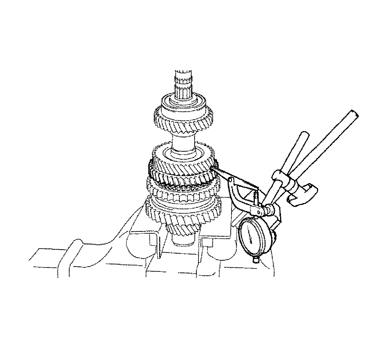
- Using a dial indicator, measure the 2nd gear thrust clearance.
Specifications
| • | Standard Clearance - 0.10-0.55 mm (0.0039-0.0217 in) |
| • | Minimum Clearance - 0.55 mm (0.0217 in) |
- If the clearance exceeds the maximum, replace the No. 1 transmission clutch hub, 2nd gear or 3rd driven gear.
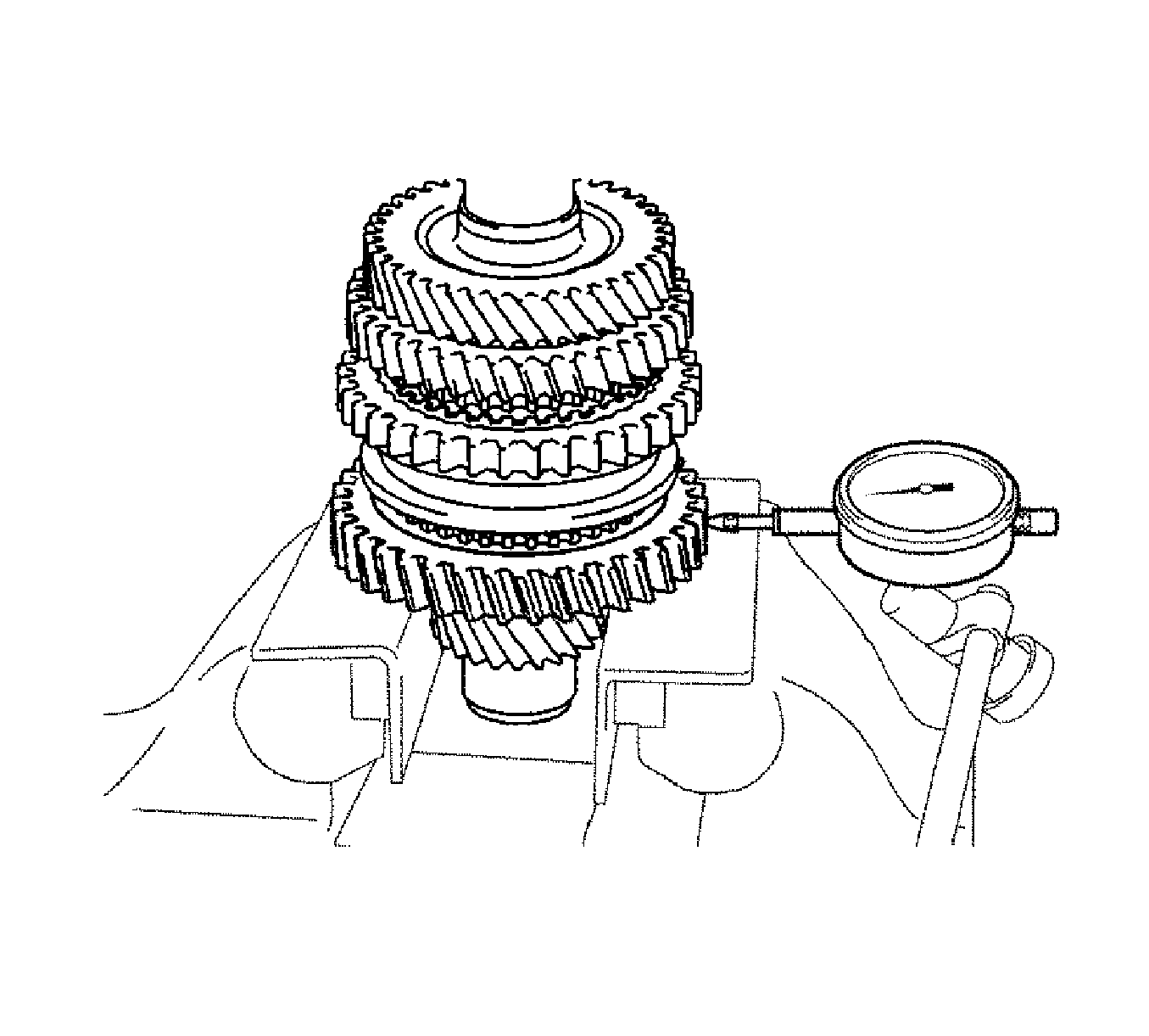
- Using a dial indicator, measure the 1st gear radial clearance.
Specifications
| • | Standard Clearance, NSK made bearing - 0.015-0.056 mm (0.0005-0.0022 in) |
| • | Standard Clearance, KOYO made bearing - 0.015-0.058 mm (0.0005-0.0022 in) |
| • | Maximum Clearance, NSK made bearing - 0.056 mm (0.0022 in) |
| • | Maximum Clearance, KOYO made bearing - 0.058 mm (0.0022 in) |
- If the clearance exceeds the maximum, replace the 1st gear, 1st gear needle roller bearing or input shaft.
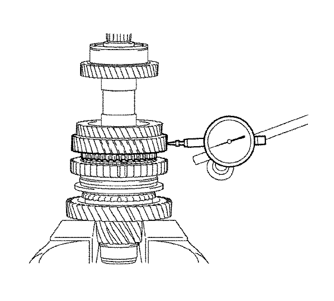
- Using a dial indicator, measure the 2nd gear radial clearance.
Specifications
| • | Standard Clearance, NSK made bearing - 0.015-0.056 mm (0.0005-0.0022 in) |
| • | Standard Clearance, KOYO made bearing - 0.015-0.058 mm (0.0005-0.0022 in) |
| • | Maximum Clearance, NSK made bearing - 0.056 mm (0.0022 in) |
| • | Maximum Clearance, KOYO made bearing - 0.058 mm (0.0022 in) |
- If the clearance exceeds the maximum, replace the 2nd gear, 2nd gear needle roller bearing or input shaft.
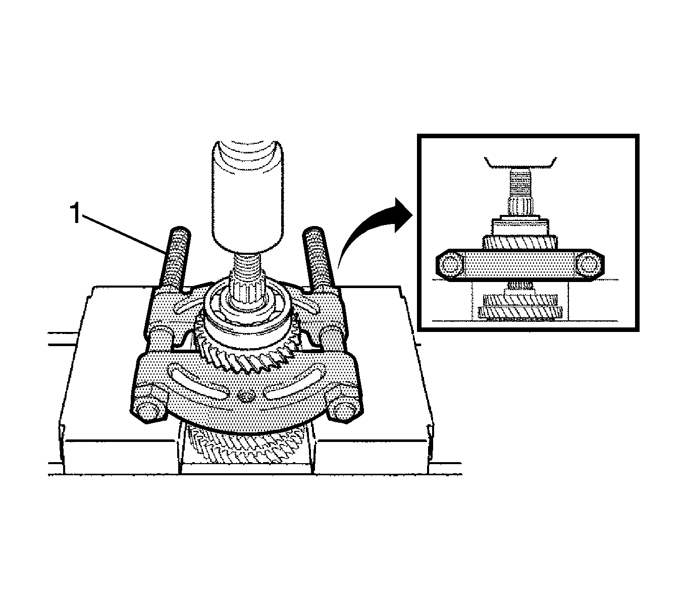
- Using a press (1), remove the output shaft rear bearing and 4th driven gear from the output shaft.
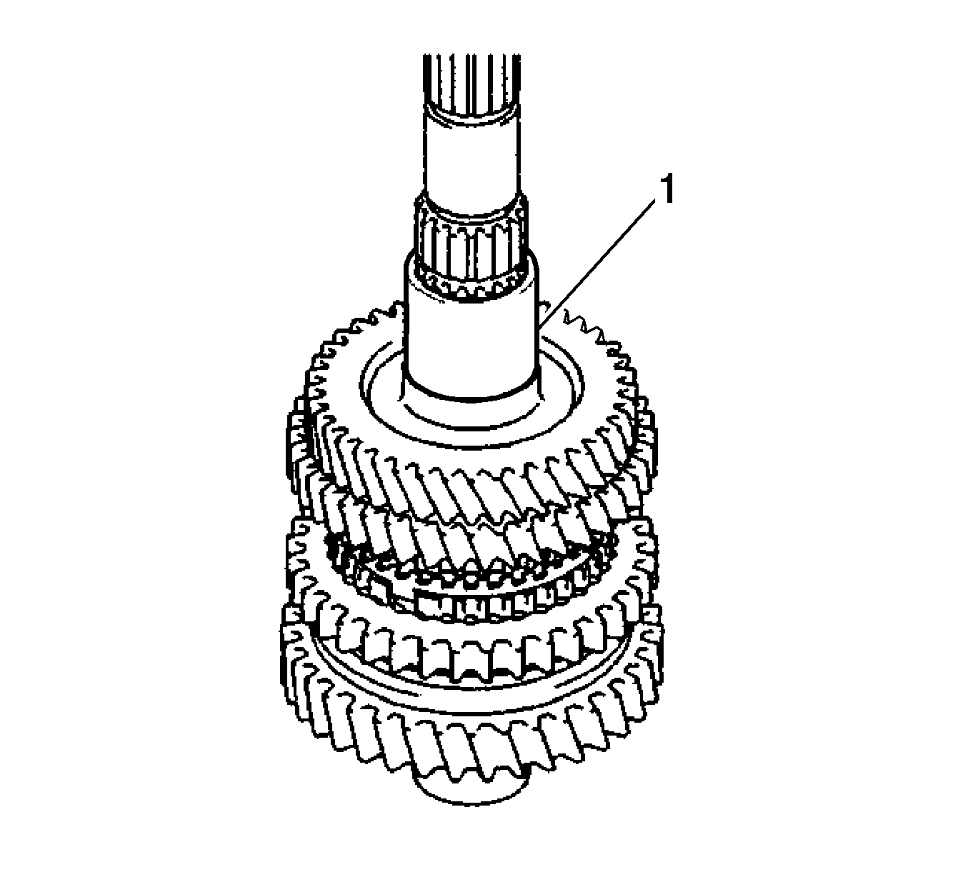
- Remove the output gear spacer (1) from the output shaft.
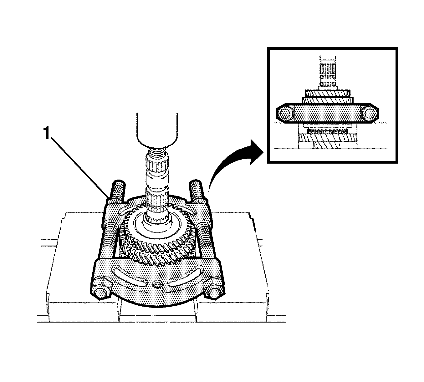
- Using a press (1), remove the 3rd driven gear with the 2nd gear from the output shaft.
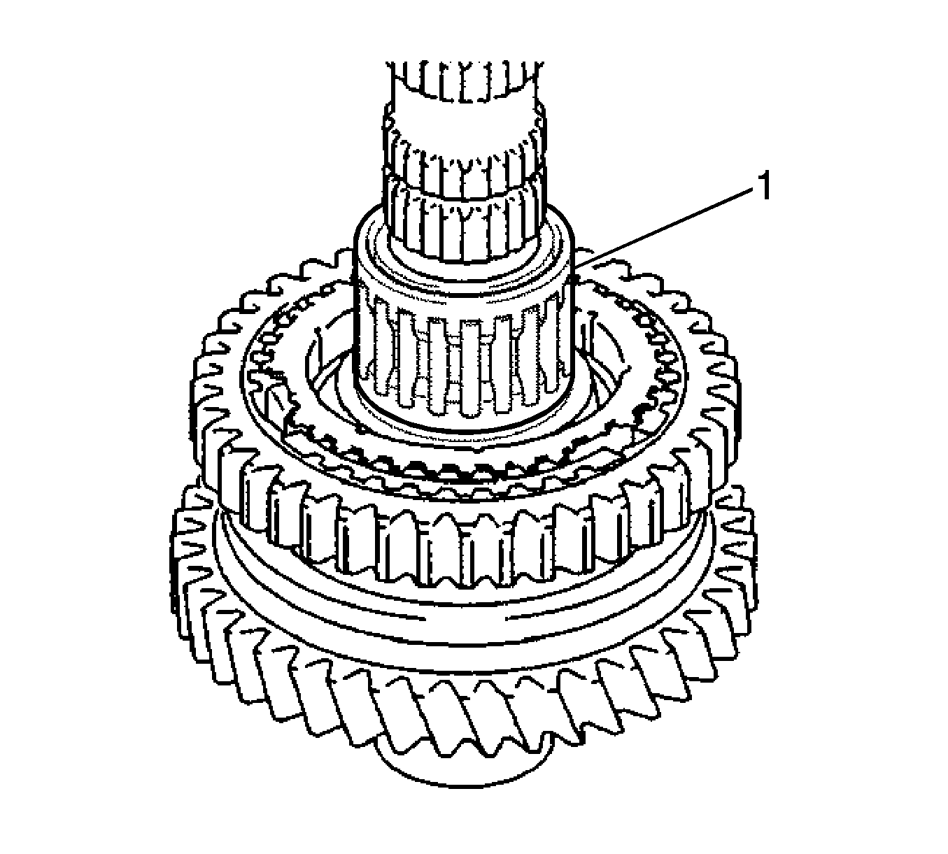
- Remove the 2nd gear needle roller bearing (1) and 2nd gear bearing spacer from the output shaft.
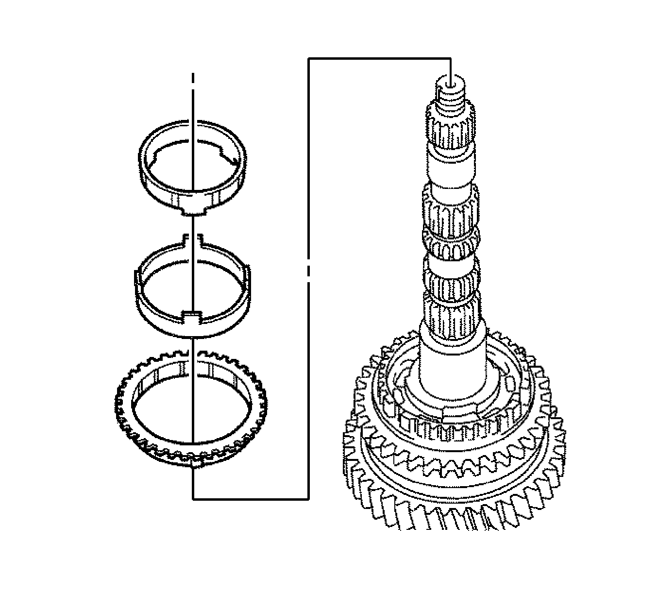
- Remove the No. 2 synchronizer ring set from the output shaft.
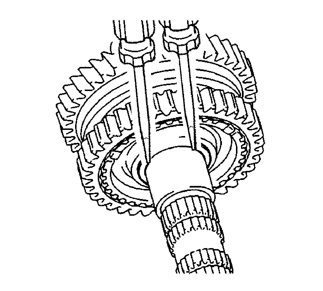
Note: Use a shop rag or piece of cloth to keep the shaft snap ring from flying off.
- Using 2 screwdrivers and a hammer, remove the No. 1 clutch hub shaft snap ring from the output shaft.
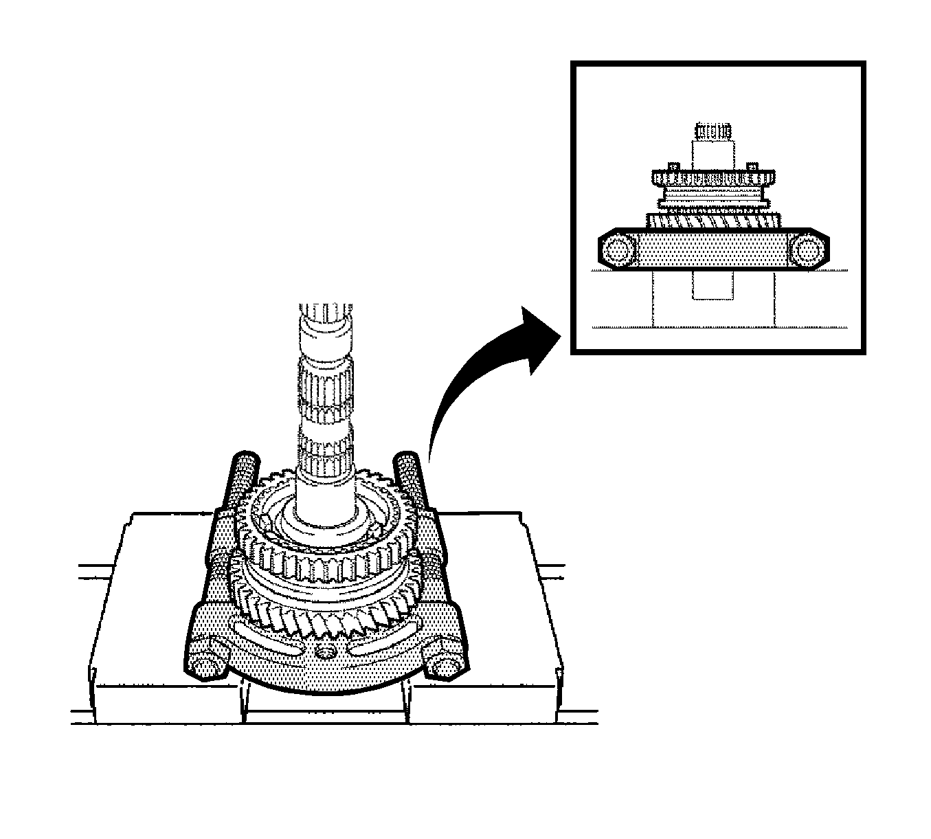
Note: Support the input shaft by hand to prevent it from dropping off.
- Using a press, remove the No. 1 clutch hub assembly and 1st gear from the output shaft.
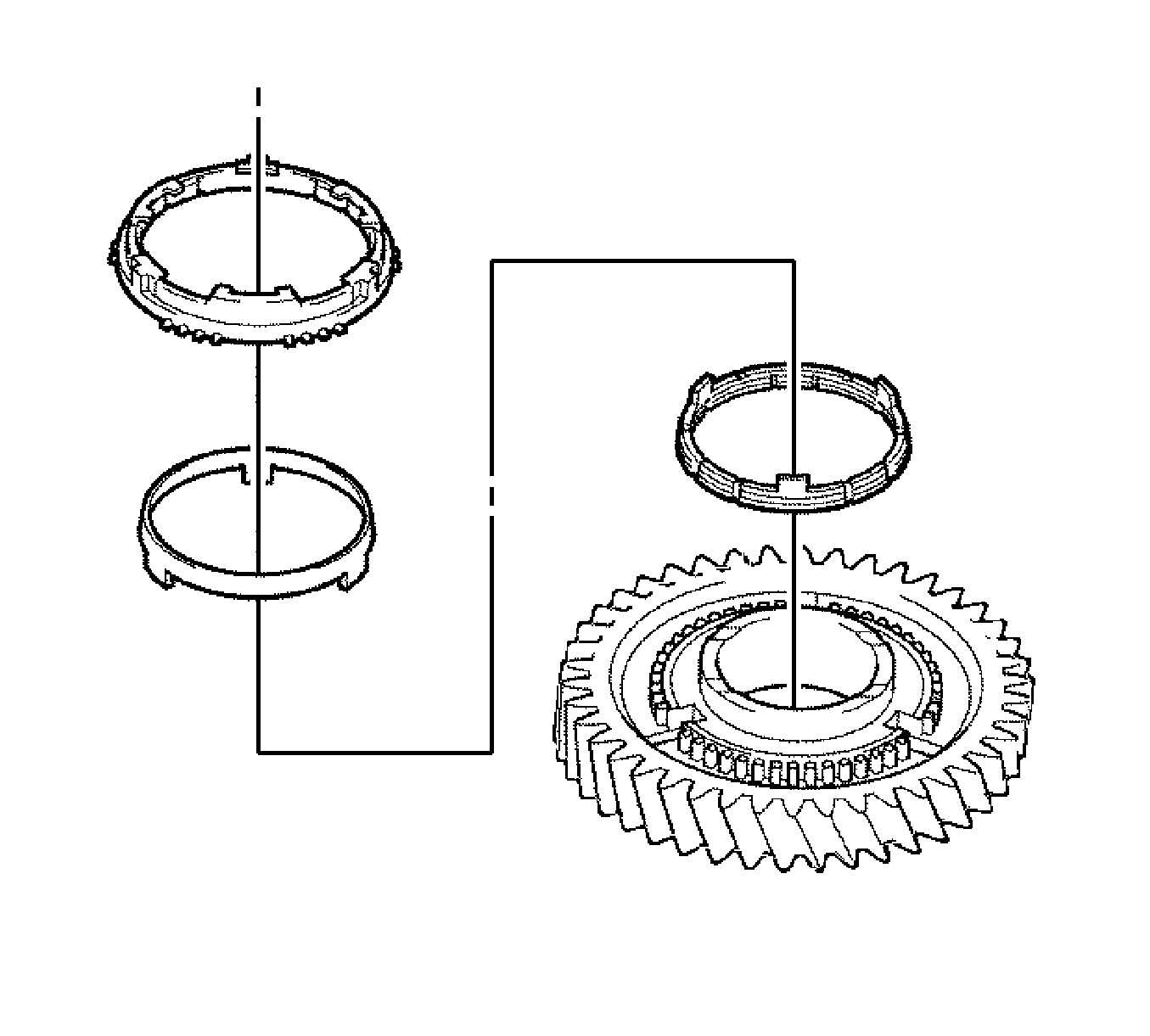
- Remove the No. 1 synchronizer ring set from the 1st gear.
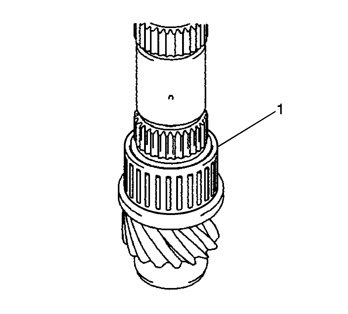
- Remove the 1st gear needle roller bearing (1) from the output shaft.
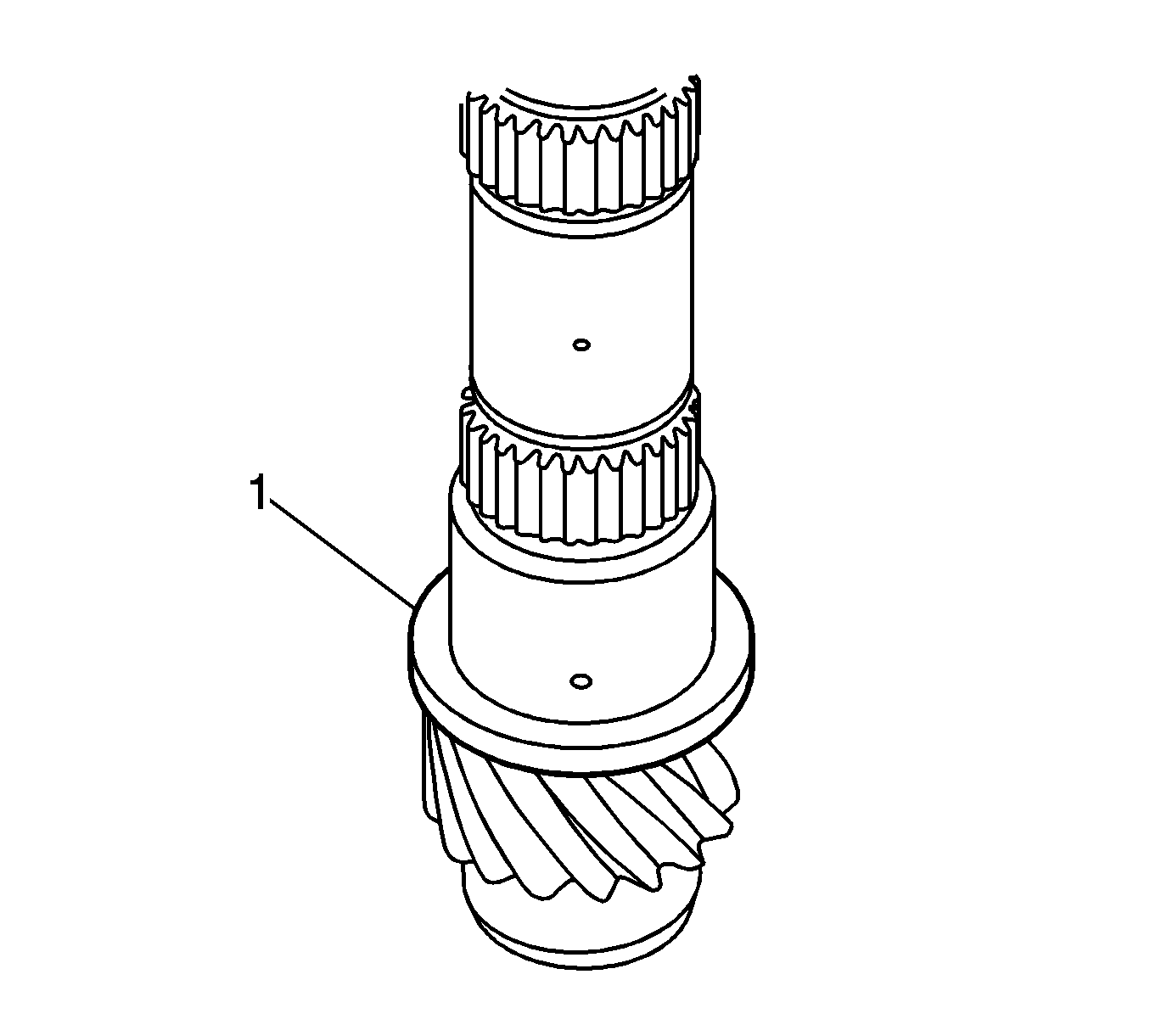
- Remove the 1st gear thrust washer (1) from the output shaft.
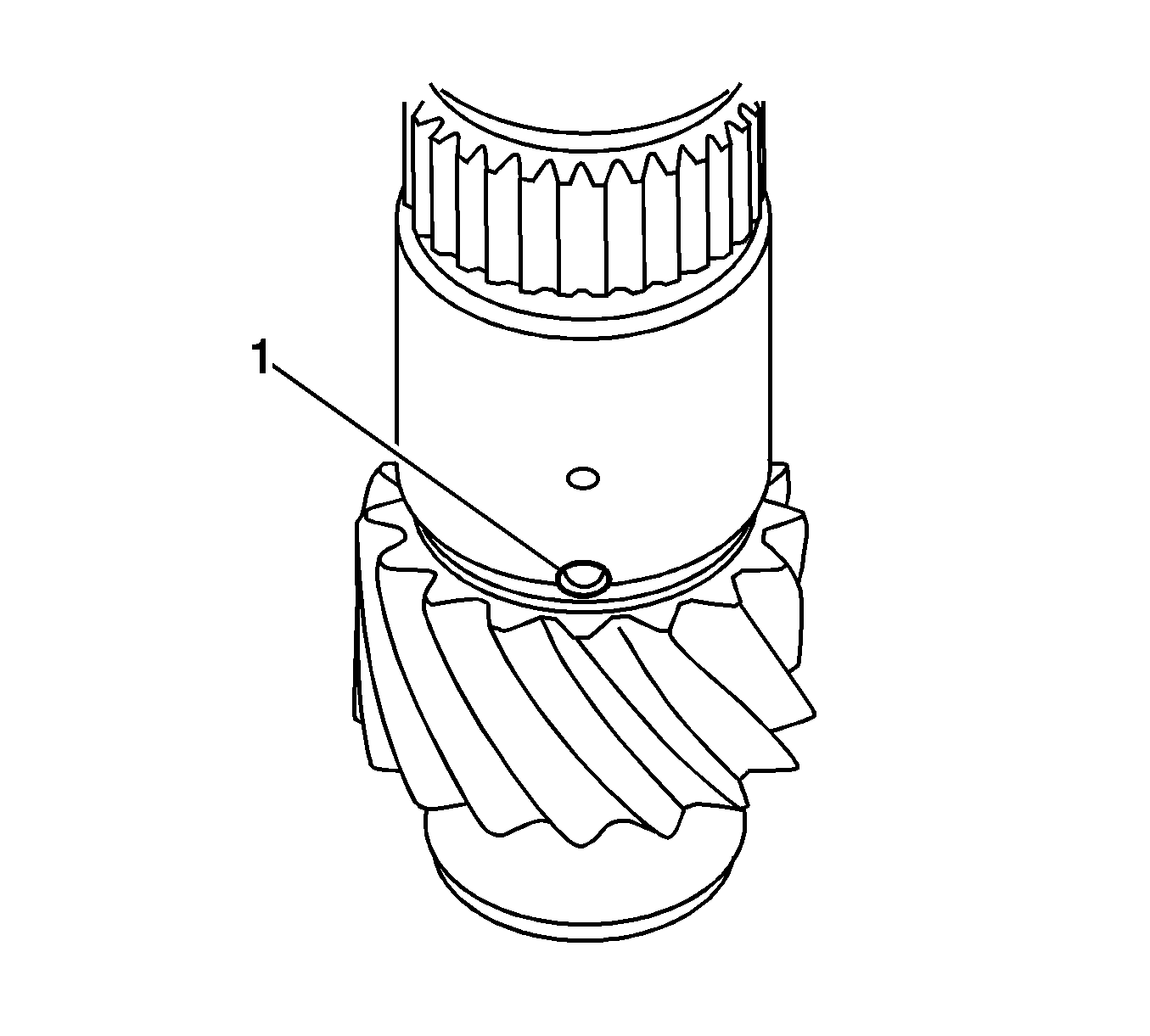
- Remove the 1st gear thrust washer pin or ball (1) from the output shaft.
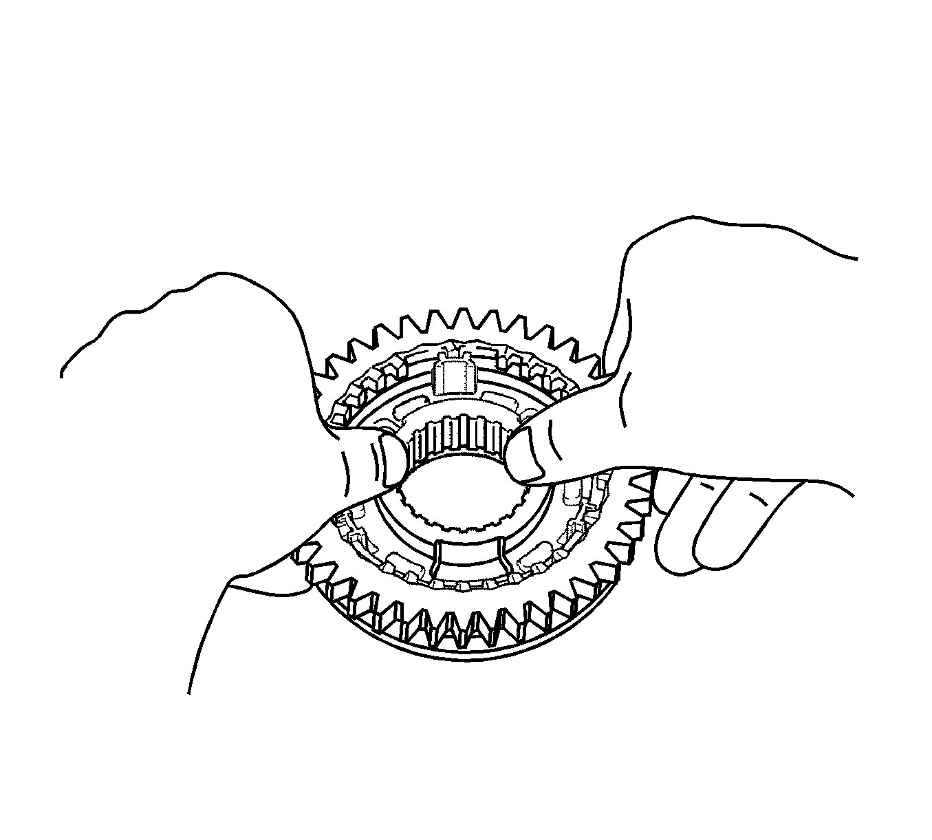
Note: Use a shop rag or piece of cloth to keep the shifting keys and shifting key springs from flying off.
- Remove the reverse gear, synchromesh shifting keys, and synchromesh shifting key springs from the No. 1 transmission clutch hub.
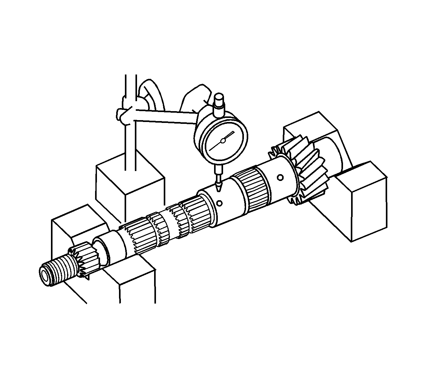
- Using a dial indicator and V-blocks, check the output shaft runout.
Specification
Maximum Runout - 0.015 mm (0.0005 in)
- If the runout exceeds the maximum, replace the output shaft.
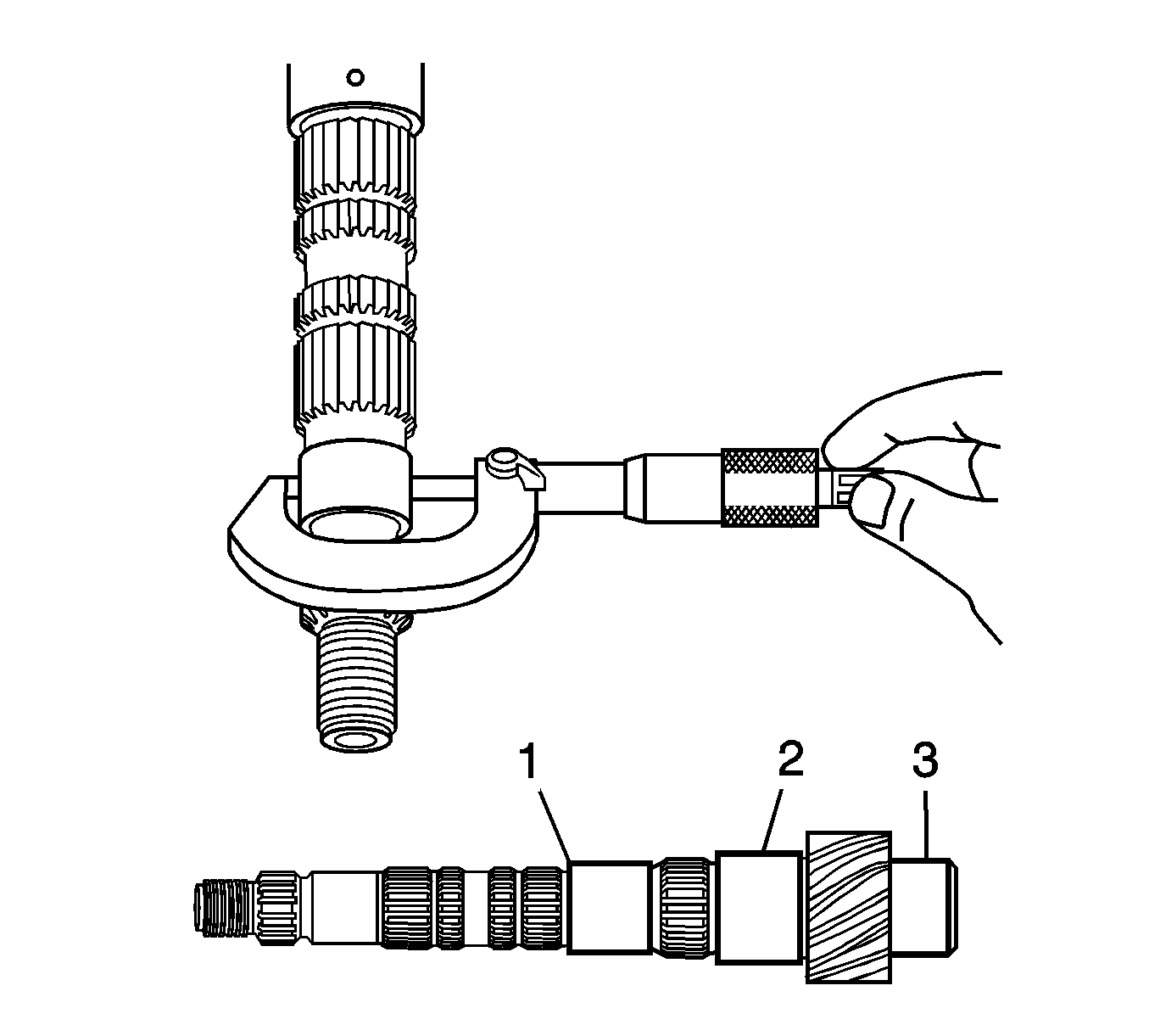
- Using a micrometer, measure the outer diameter of the output shaft journal surface at the locations indicated.
Specifications
| • | Standard Outer Diameter, Part 1 - 31.985-32.000 mm (1.2592-1.2598 in) |
| • | Standard Outer Diameter, Part 2 - 37.985-38.000 mm (1.4955-1.4961 in) |
| • | Standard Outer Diameter, Part 3 - 32.985-33.000 mm (1.2986-1.2992 in) |
- If any of the outer diameters are less than the minimum, replace the output shaft.
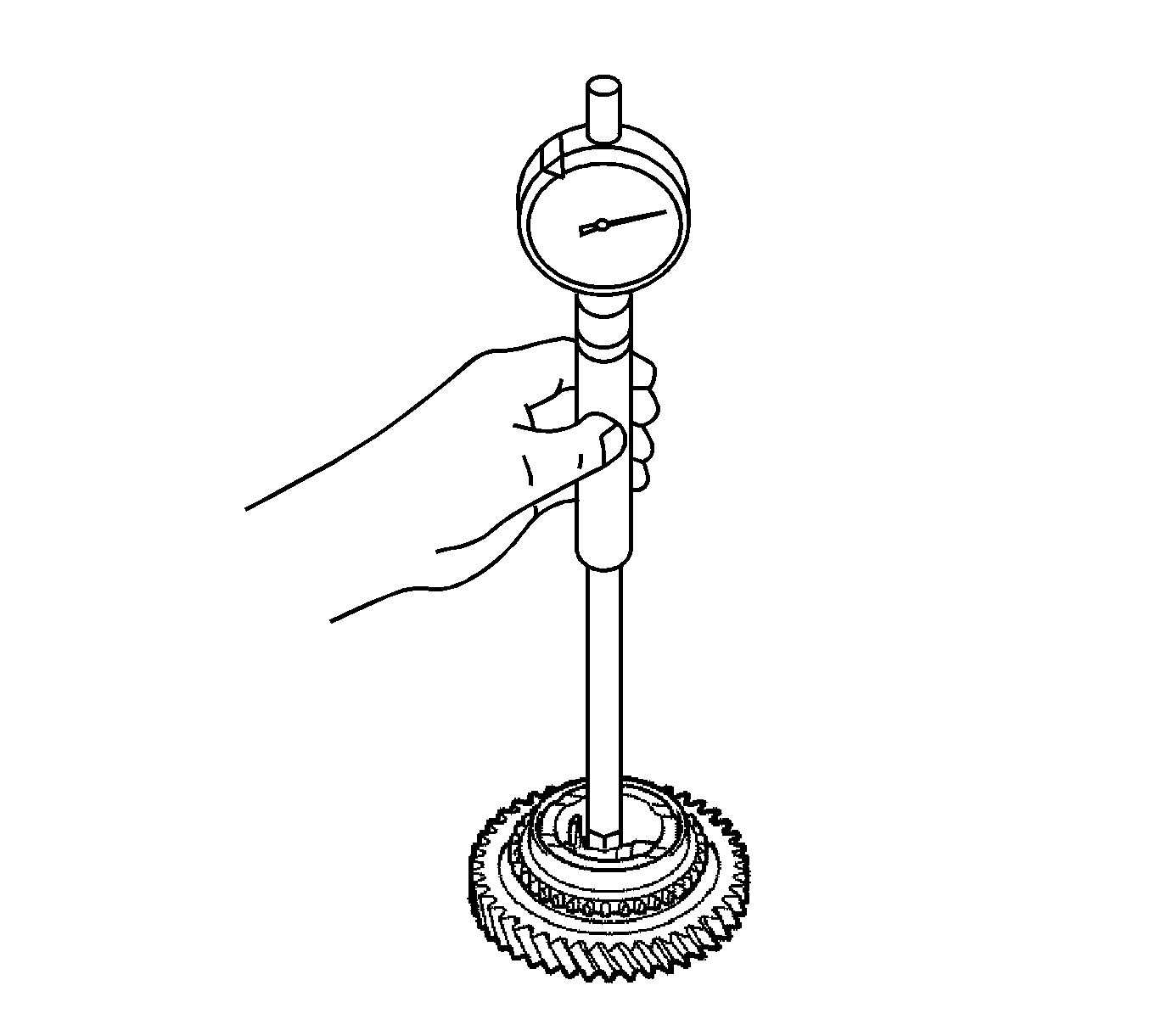
- Using a cylinder gage, measure the inside diameter of the 2nd gear.
Specifications
| • | Standard Inside Diameter - 38.015-38.031 mm (1.4967-1.4972 in) |
| • | Maximum Inside Diameter - 38.031 mm (1.4972 in) |
- If the inside diameter exceeds the maximum, replace the 1st gear.
- Using a cylinder gage, measure the inside diameter of the 1st gear.
Specifications
| • | Standard Inside Diameter - 44.015-44.031 mm (1.7328-1.7335 in) |
| • | Maximum Inside Diameter - 44.031 mm (1.7335 in) |
- If the inside diameter exceeds the maximum, replace the 1st gear.
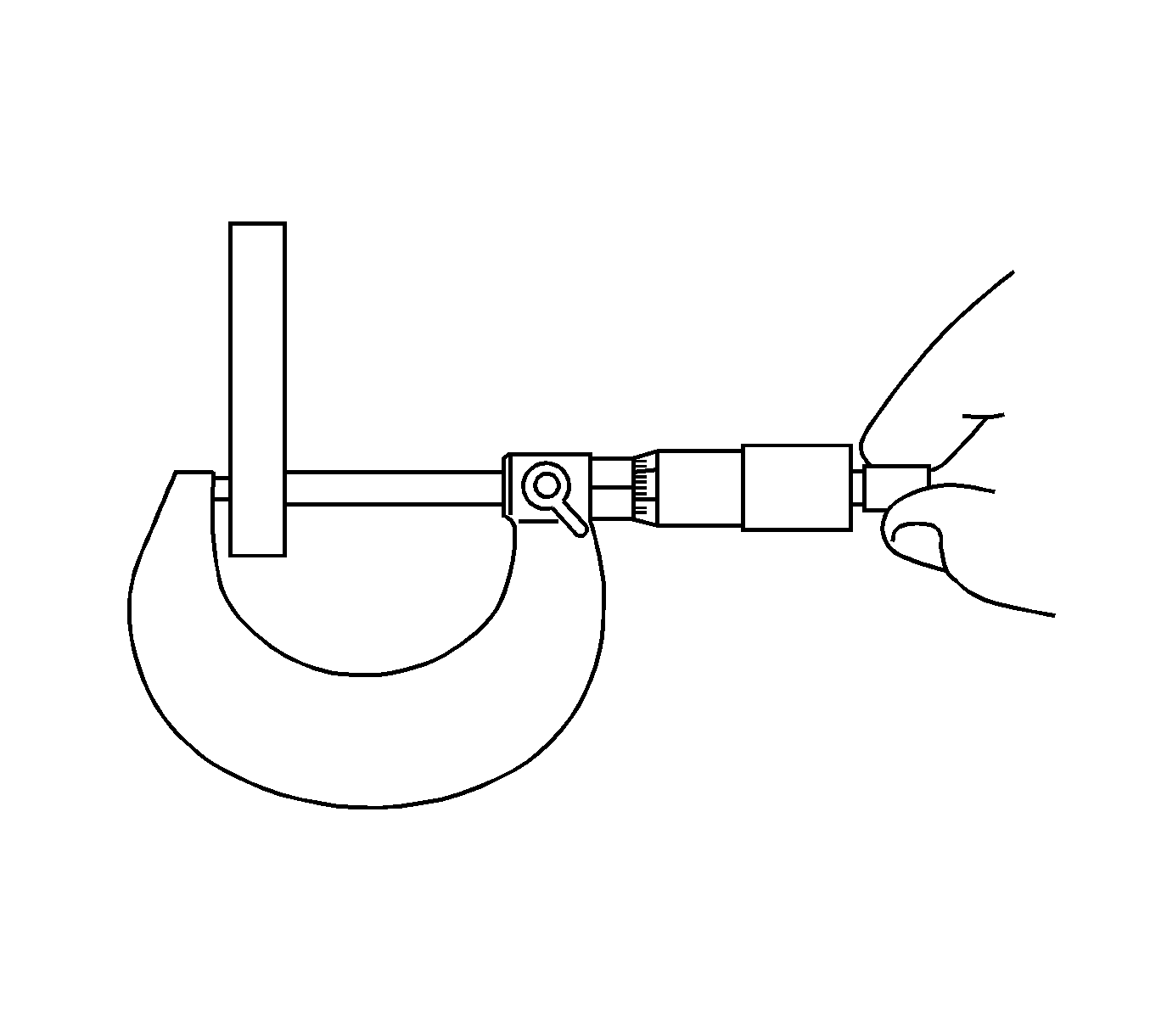
- Using a micrometer, measure the 1st gear thrust washer.
Specifications
| • | Standard Thickness - 5.975-6.025 mm (0.2352-0.2372 in) |
| • | Minimum Thickness - 5.975 mm (0.2352 in) |
- If the thickness is less than the minimum, replace the 1st gear thrust washer.
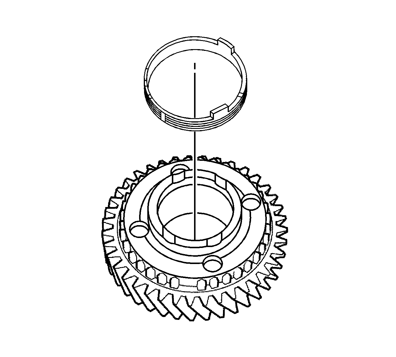
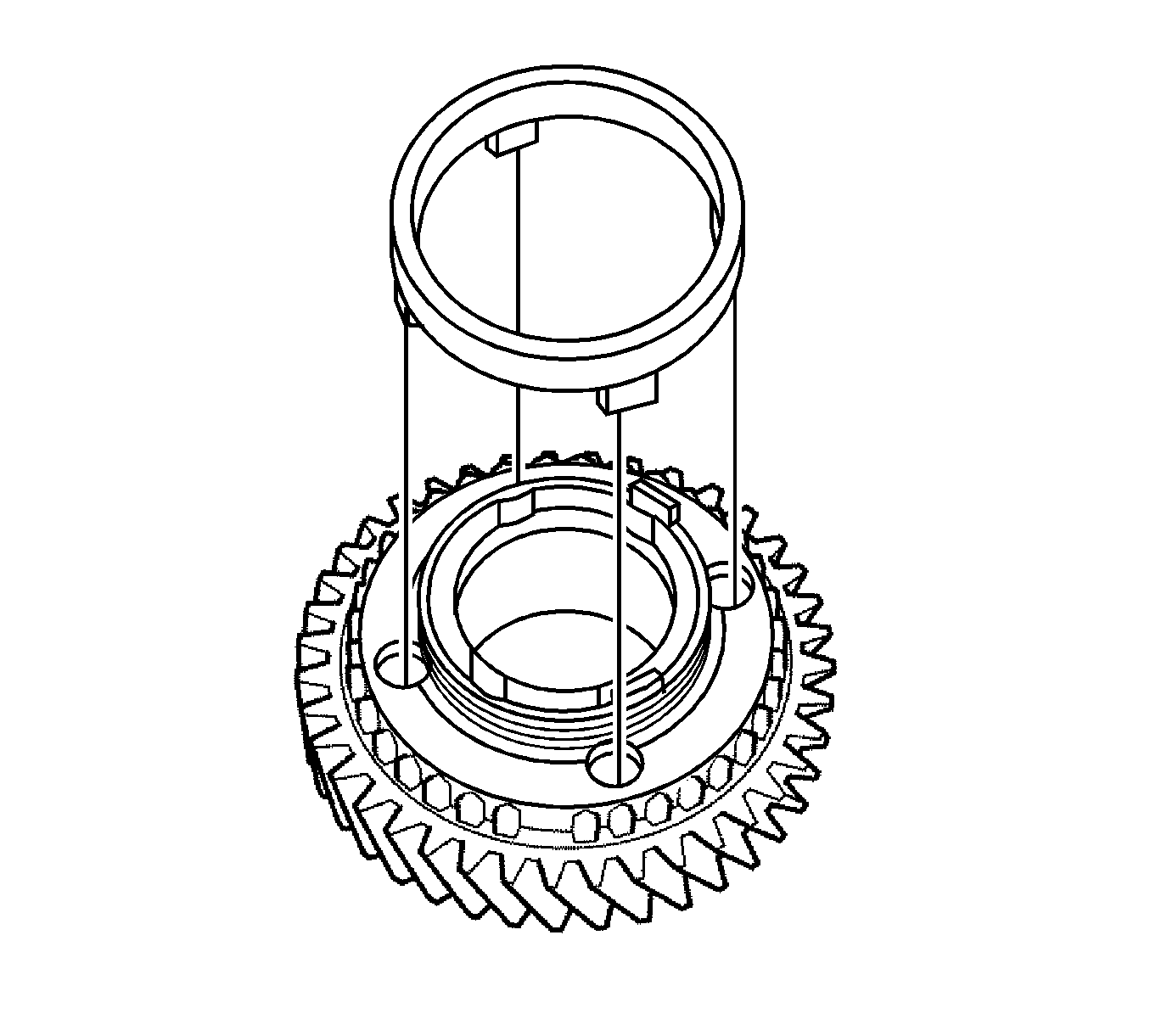
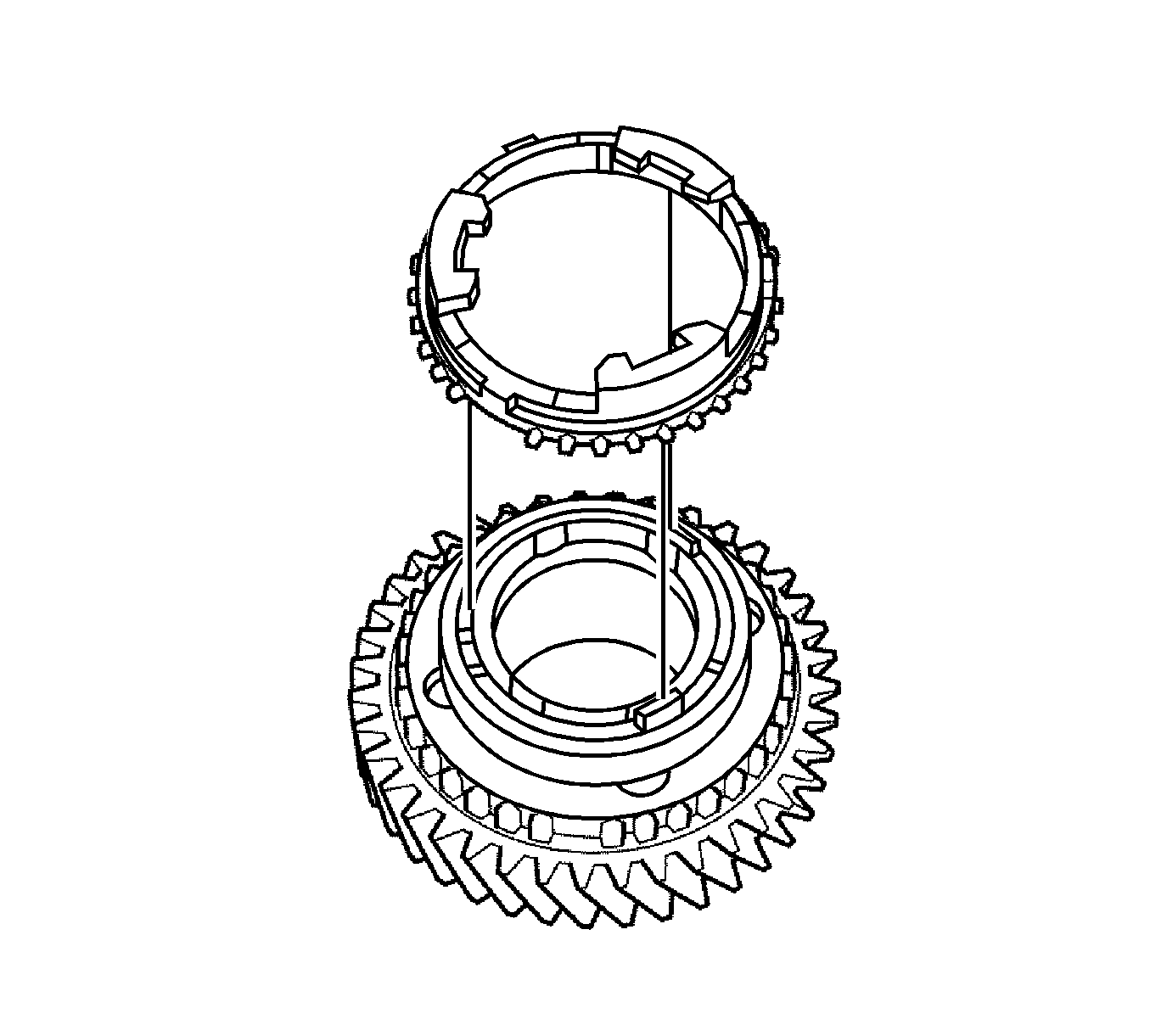
- Coat the 2nd gear cone and No. 2 synchronizer ring set (inner ring, middle ring, and outer ring) with gear oil.
- Install the inner ring onto the 2nd gear.
- Install the middle ring onto the 2nd gear.
- Install the outer ring onto the 2nd gear.
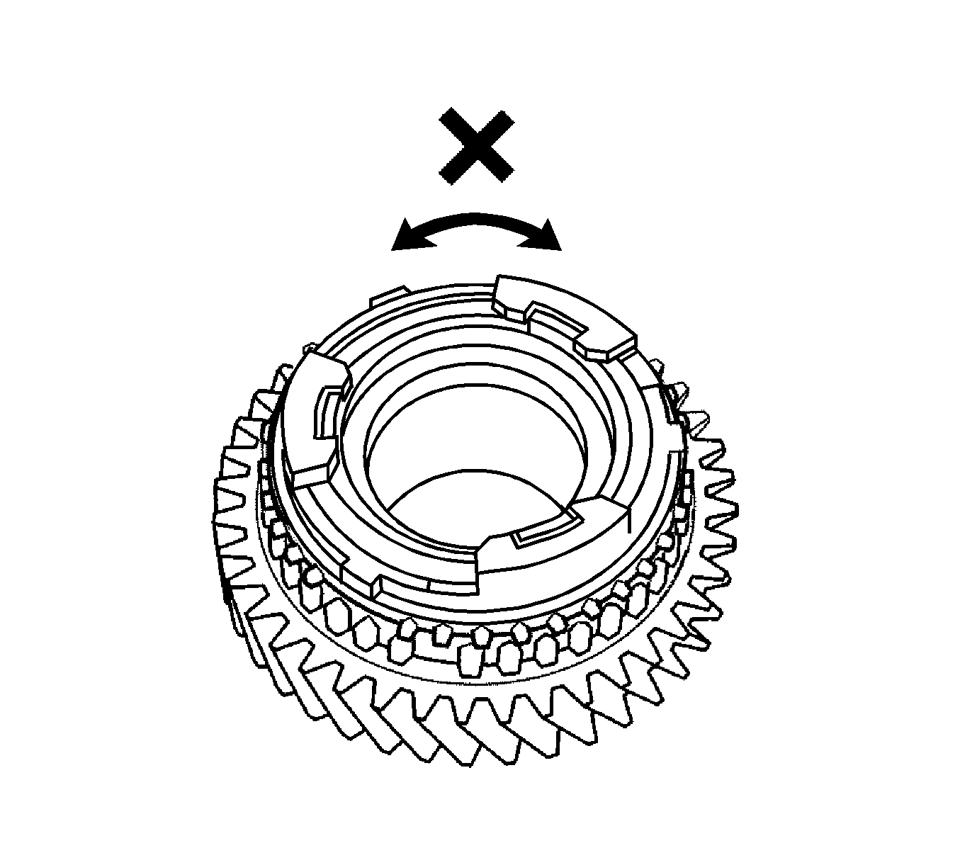
- Check for wear and damage.
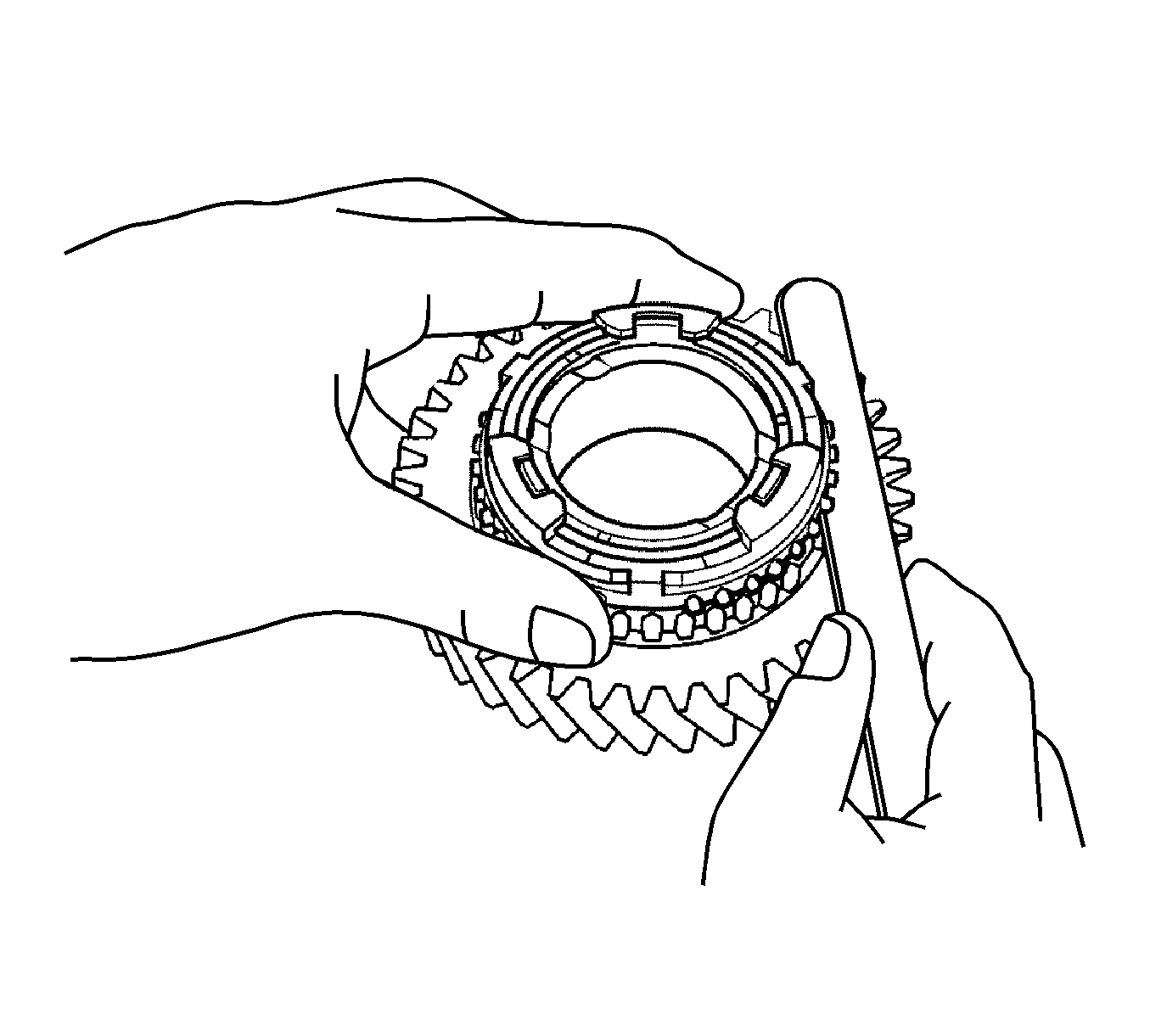
- Turn the synchronizer ring set in one direction while pushing it against the 2nd gear cone.
- Check that the ring set locks.
If the synchronizer ring set does not lock, replace the synchronizer ring set.
- Using a feeler gage, measure the clearance between the synchronizer ring and the gear spline end.
Specifications
| • | Standard Clearance - 0.60-1.40 mm (0.0236-0.0551 in) |
| • | Minimum Clearance - 0.60 mm (0.0236 in) |
- If the clearance is less than the minimum, replace the synchronizer ring set.
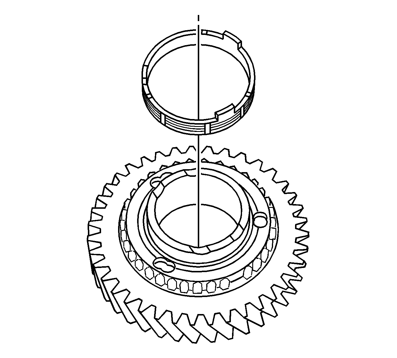
- Coat the 1st gear cone and No. 1 synchronizer ring set (inner ring, middle ring, and outer ring) with gear oil.
- Install the inner ring onto the 1st gear.
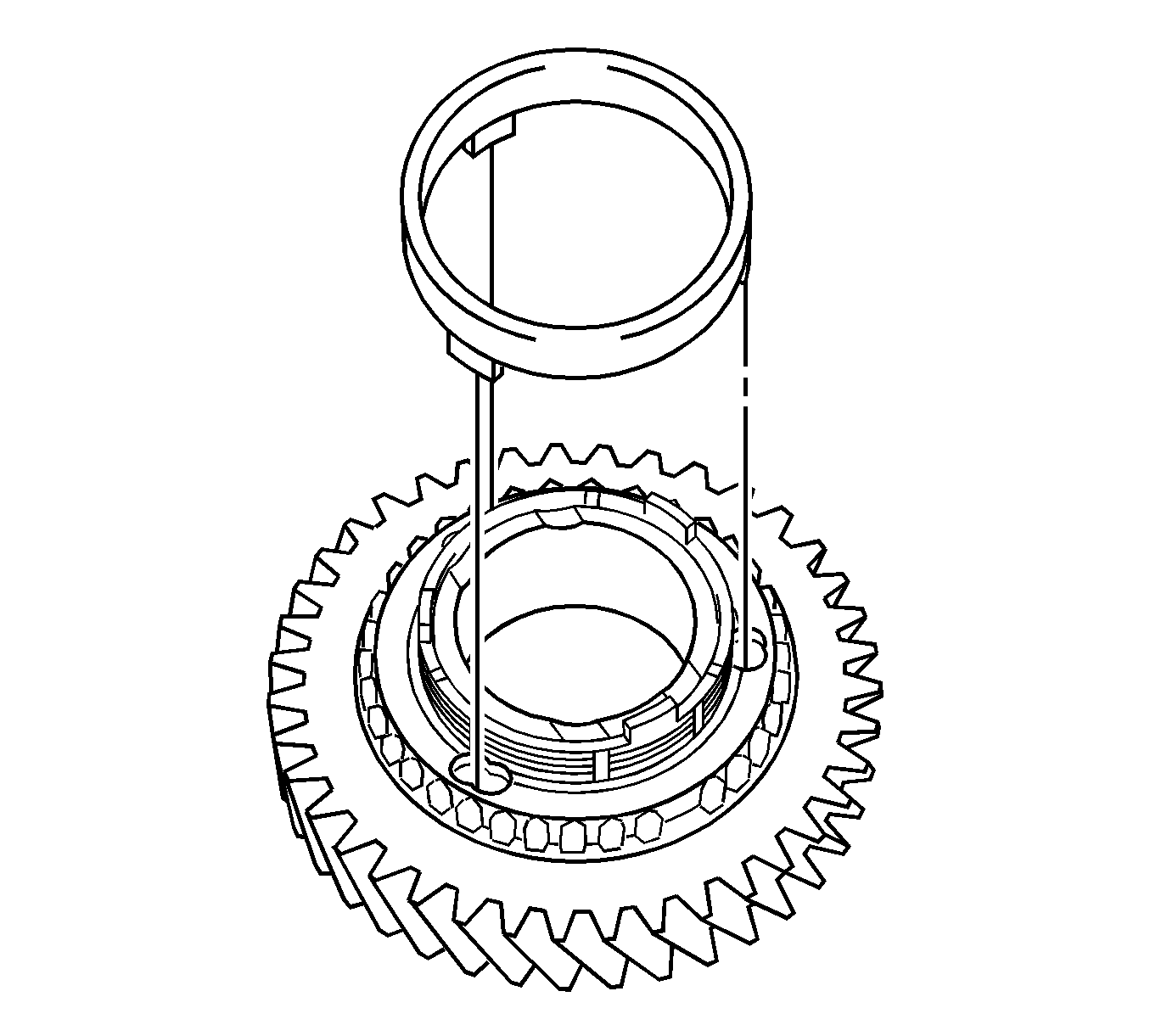
- Install the middle ring onto the 1st gear.
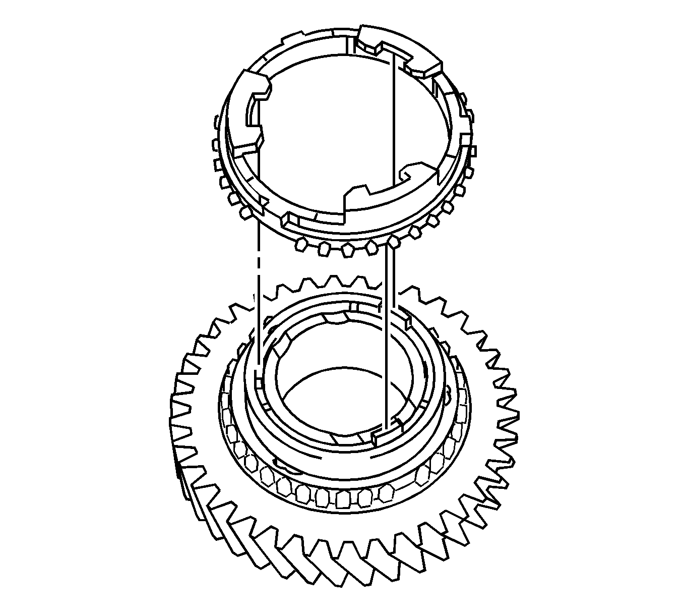
- Install the outer ring onto the 1st gear.
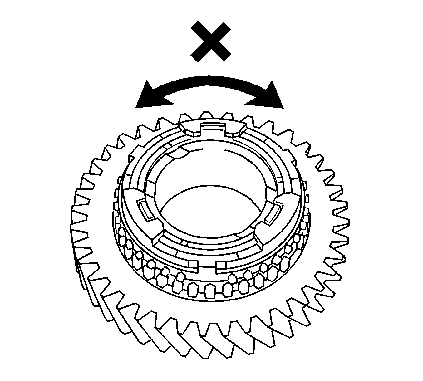
- Check for wear and damage.
- Turn the synchronizer ring set in one direction while pushing it against the 1st gear cone.
- Check that the ring set locks.
If the synchronizer ring set does not lock, replace the synchronizer ring set.
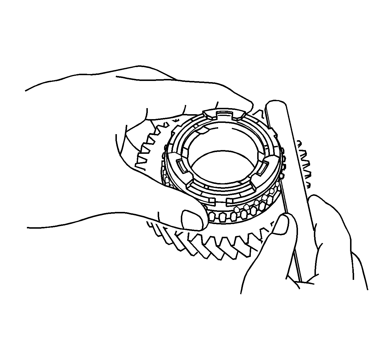
- Using a feeler gage, measure the clearance between the synchronizer ring and the gear spline end.
Specifications
| • | Standard Clearance - 0.60-1.40 mm (0.0236-0.0551 in) |
| • | Minimum Clearance - 0.60 mm (0.0236 in) |
- If the clearance is less than the minimum, replace the synchronizer ring set.
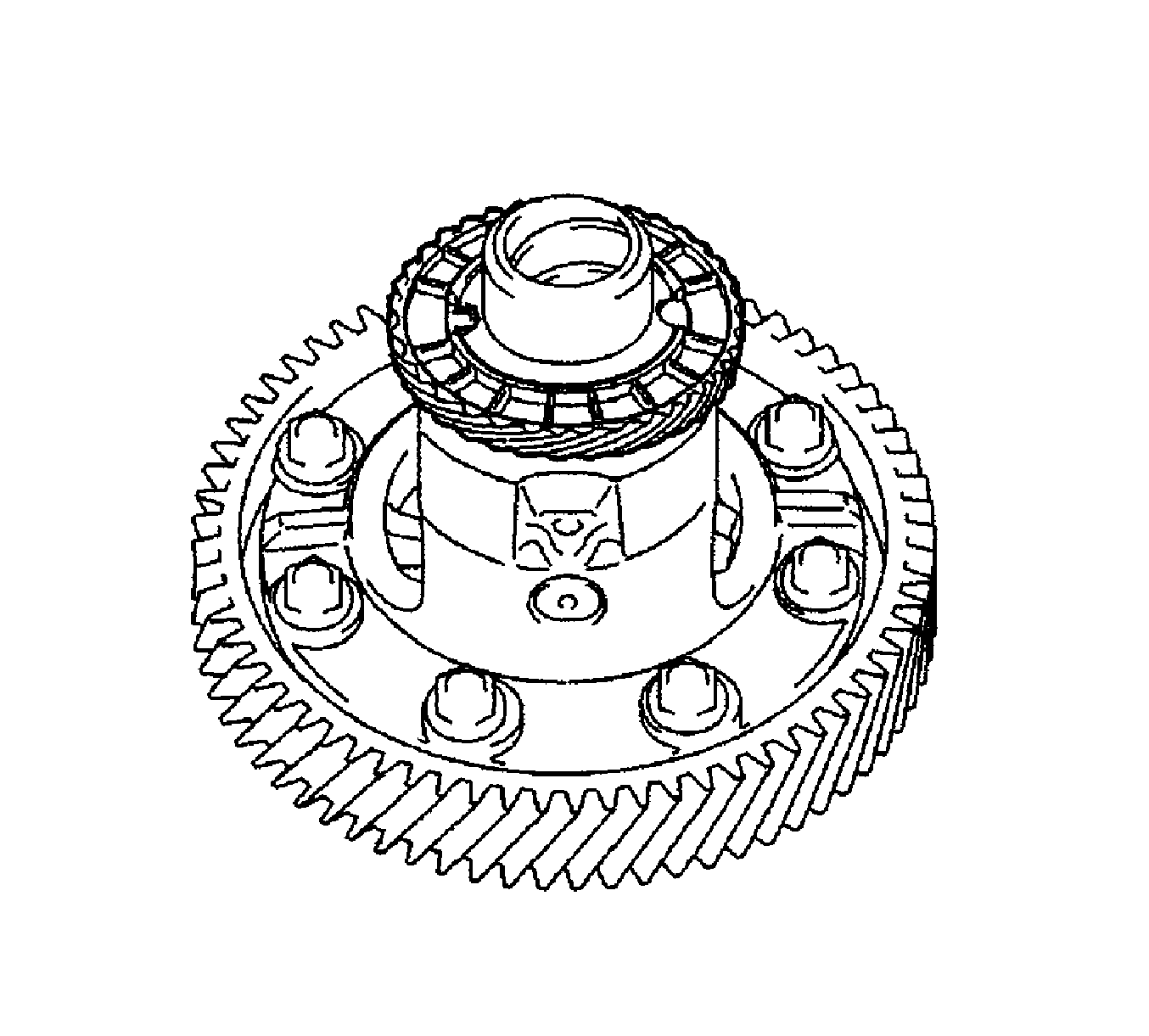
- Remove the speedometer drive gear from the front differential case.
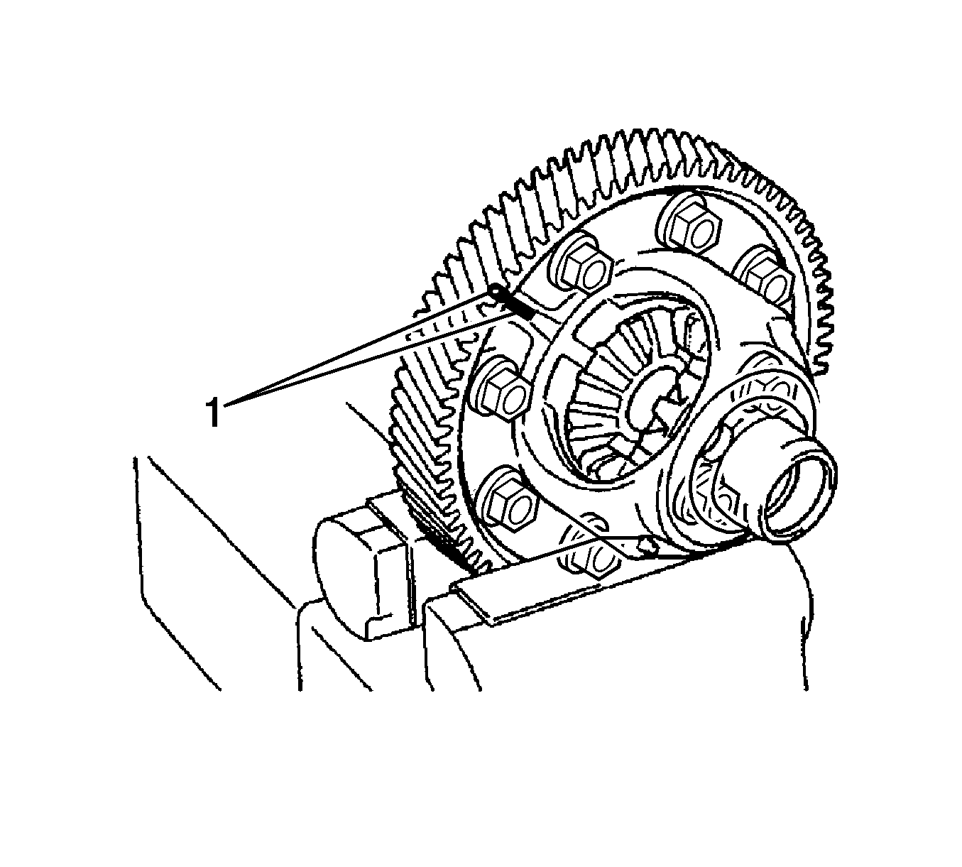
- Place matchmarks (1) on the front differential ring gear and the front differential case.
- Remove the bolts.
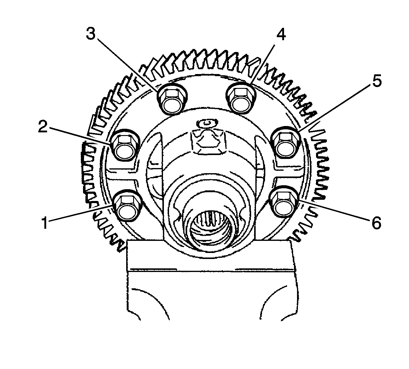
- Using a plastic hammer, remove the front differential ring gear from the front differential case.
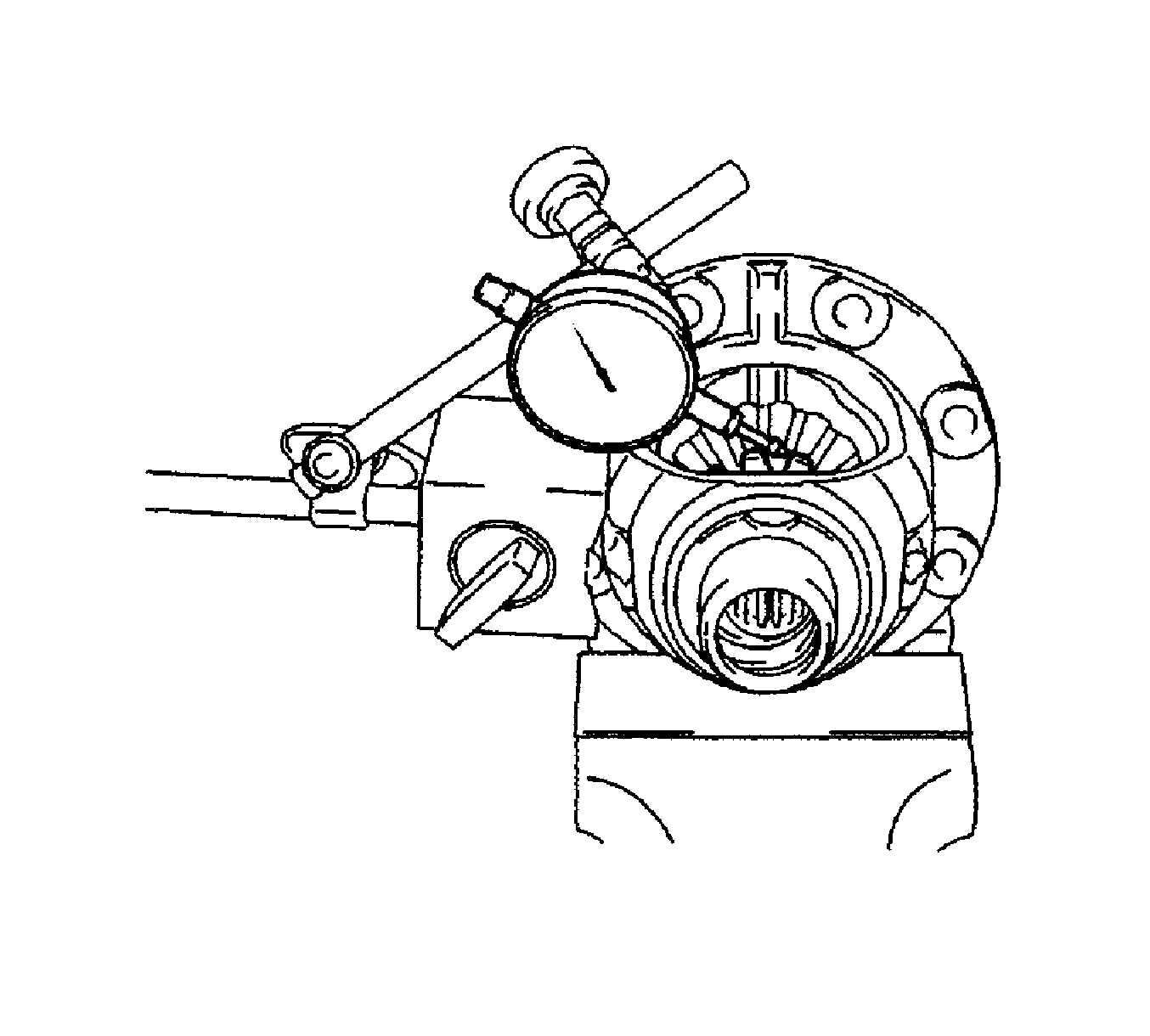
- Fix the front differential pinion to the front differential case side. Using a dial indicator, measure the front differential side
gear backlash.
Specification
Standard Backlash - 0.05 to 0.20 mm (0.0020 to 0.0079 in)
- If the backlash is out of the specification, replace the side gear thrust washers.
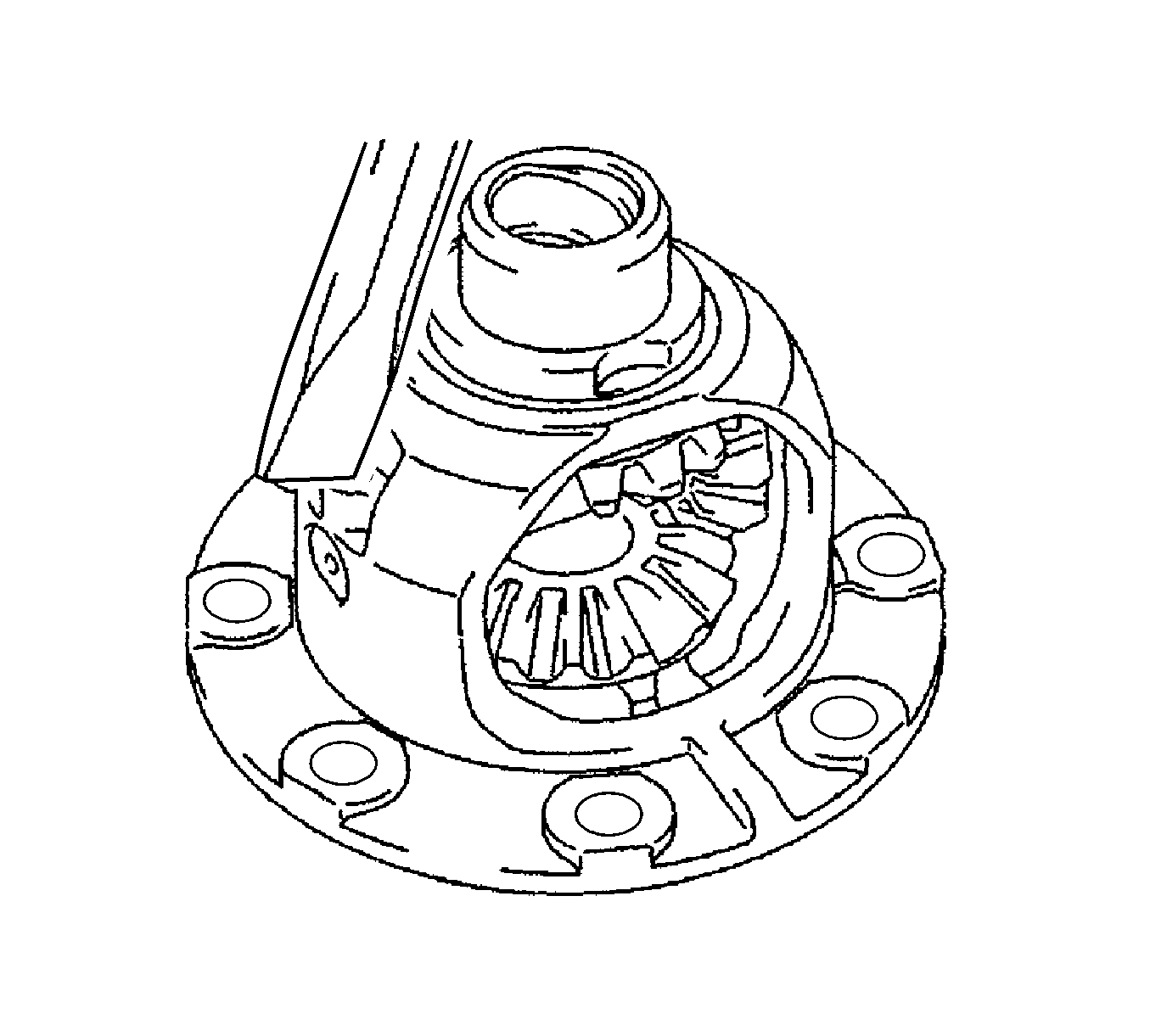
- Using a chisel and a hammer, loosen the staked part of the front differential case.
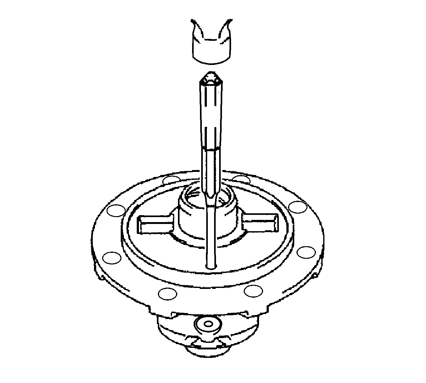
- Using a pin punch (3 mm) and a hammer, remove the front differential pinion shaft straight pin from the front differential
case.
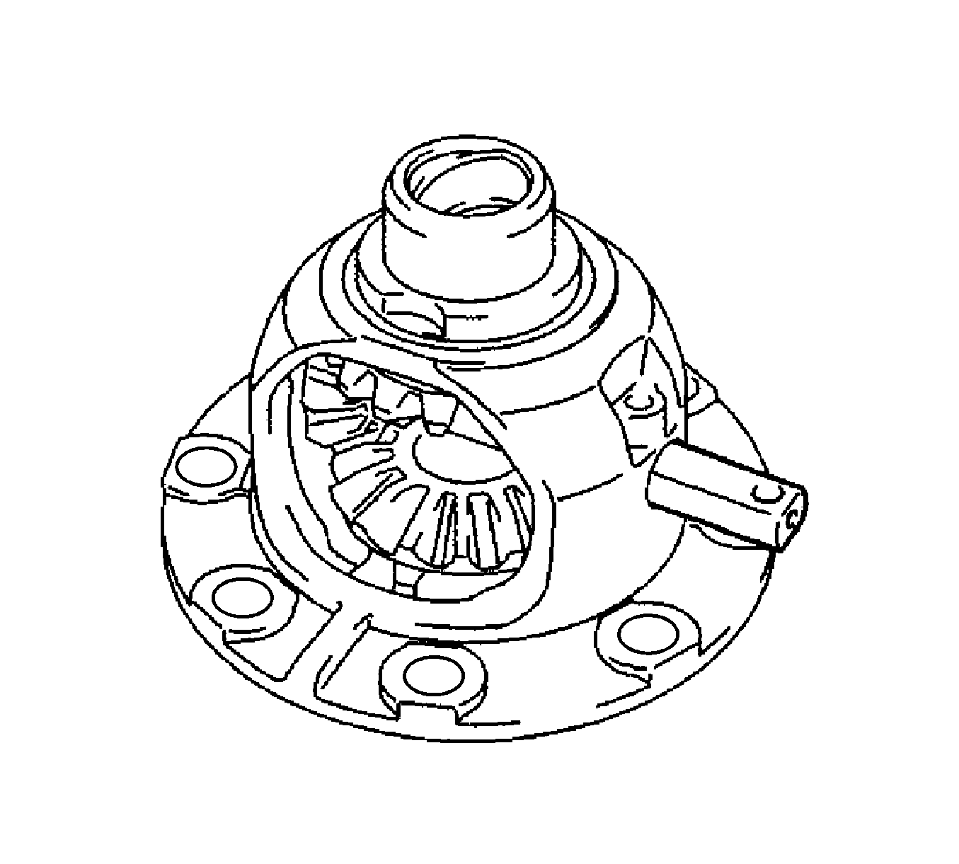
- Remove the front No. 1 differential pinion shaft from the front differential case.
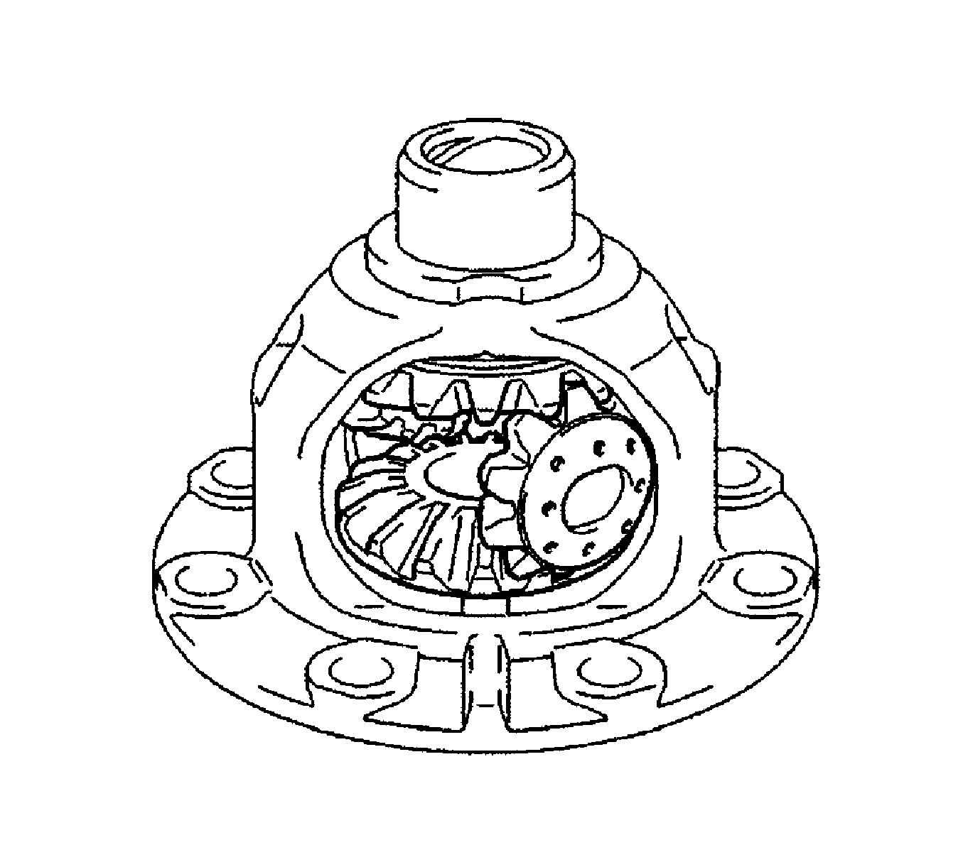
Note: While rotating the front differential pinion, remove the pinions and side gears.
- Remove the front differential pinions, front differential pinion thrust washers, No. 1 front differential side gear thrust washers, and front differential side gears from the front differential case.
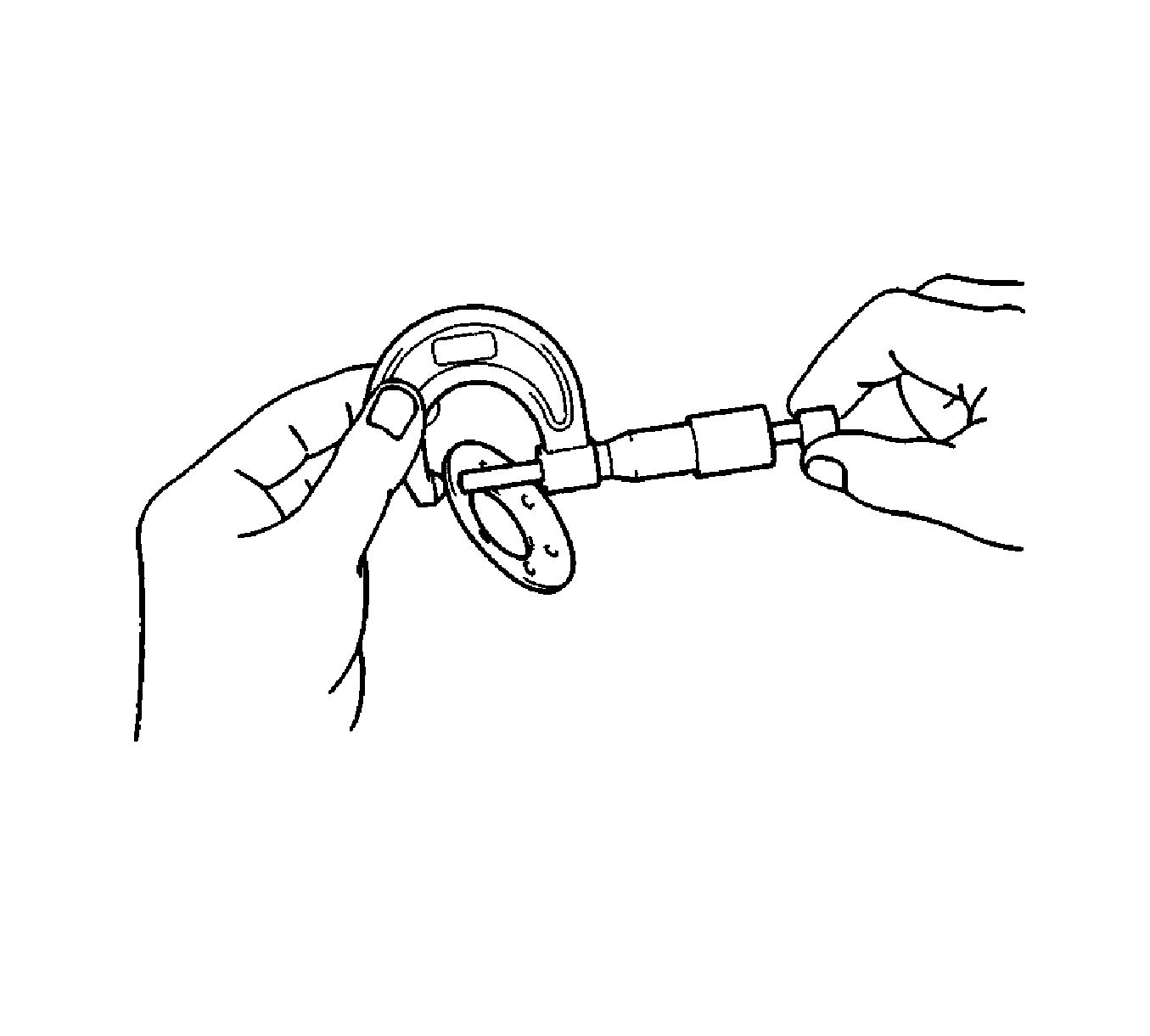
- Using a micrometer, measure the thickness of the front differential pinion thrust washer.
Specification
Minimum Thickness - 0.94 mm (0.0370 in)
- If the thickness is less than the minimum, replace the front differential pinion thrust washer.
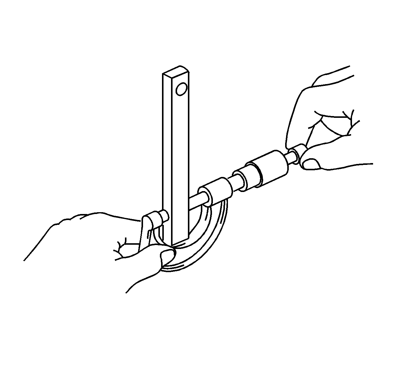
- Using a micrometer, measure the outer diameter of the front No. 1 differential pinion shaft.
Specification
Minimum Outer Diameter - 16.982 mm (0.6685 in)
- If the outer diameter is less than the minimum, replace the front No. 1 differential pinion shaft.


