Tools Required
| • | J 44015 Steering Linkage Installer |
| • | SA91100C Tie Rod Separator |
Removal Procedure
- With the vehicle on the ground, depress the brake pedal and remove the cotter and drive axle nut. Discard the nut and cotter.
- Raise the vehicle on a hoist.
- Remove the wheel and tire assembly . Refer to Tire and Wheel Removal and Installation in Tires and Wheels.
- Remove the tie rod end torque prevailing nut and discard the nut.
- Using the SA91100C , separate the tie rod end from the steering knuckle.
- Remove the lower control arm to steering knuckle nut and bolt.
- Separate the lower control arm from the steering knuckle.
- While pulling the knuckle/strut assembly away from the vehicle, pull the outer end of the drive axle out of the wheel hub.
- Support or suspend the drive axle assembly.
- Remove the drive axle from the transaxle.
- Remove the shaft retaining the ring from the end of the drive axle or stub shaft and discard. The stub shaft is shown.

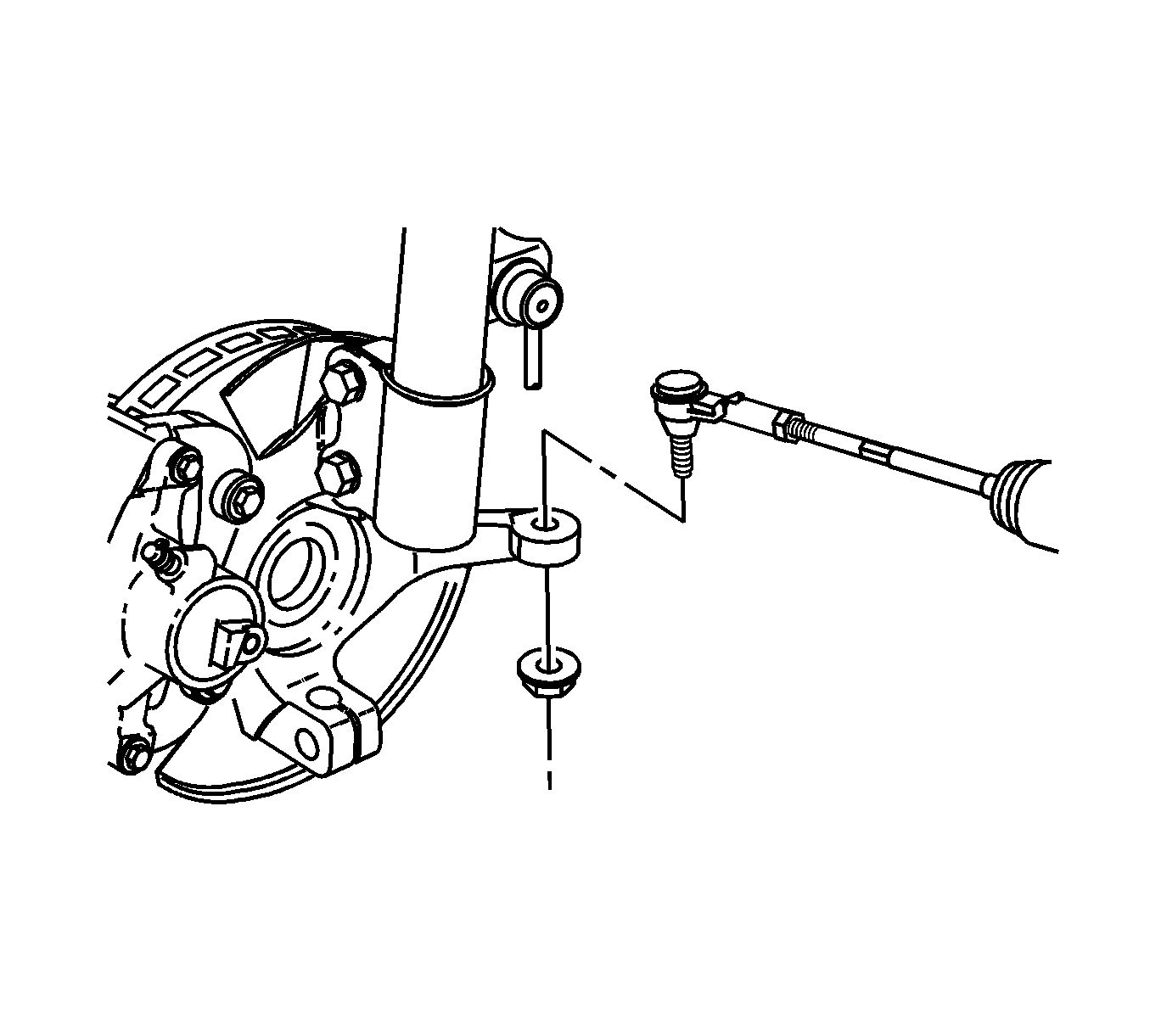
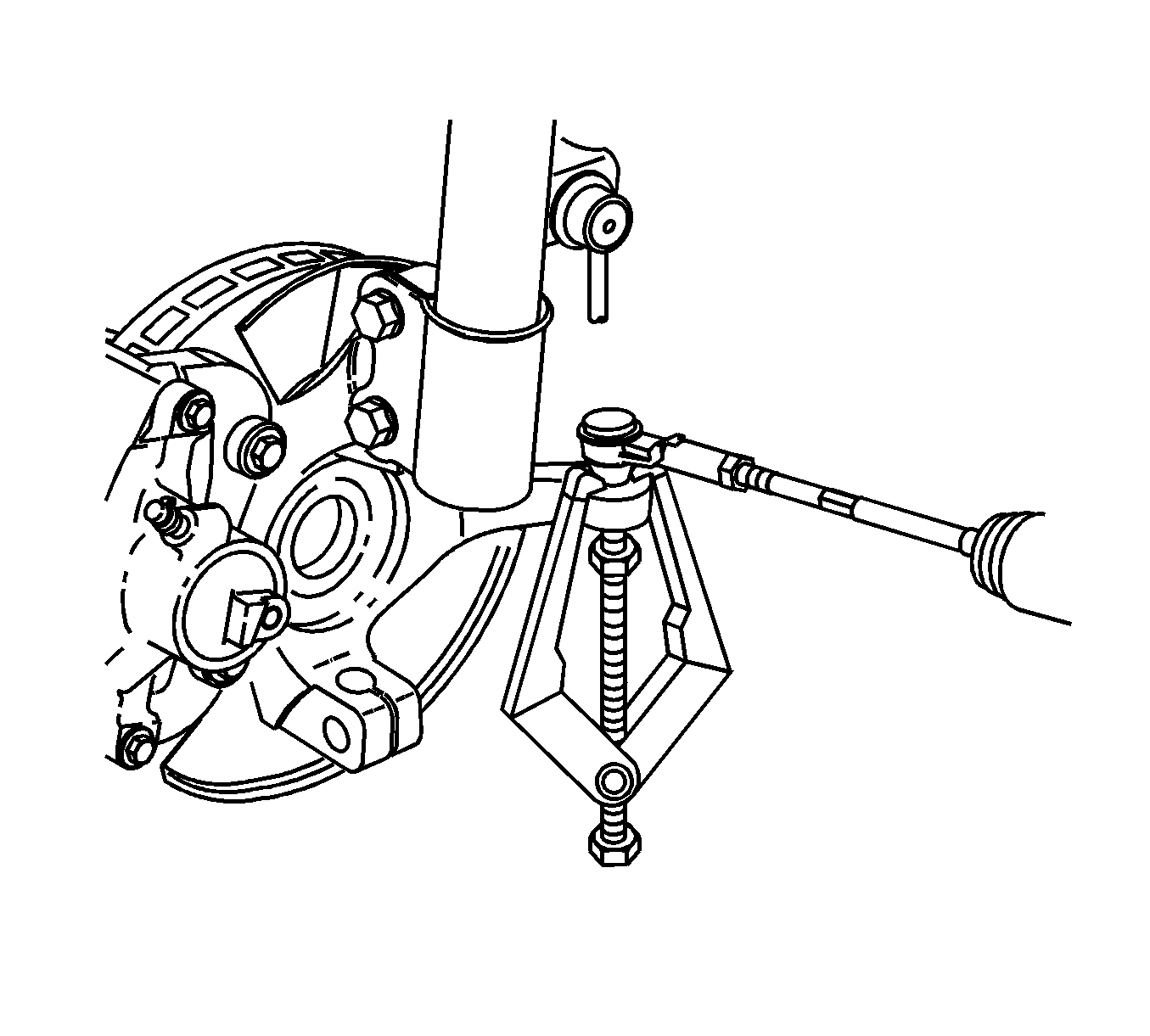
Notice: Do not attempt to separate the joint using a wedge-type tool because seal may be damaged.
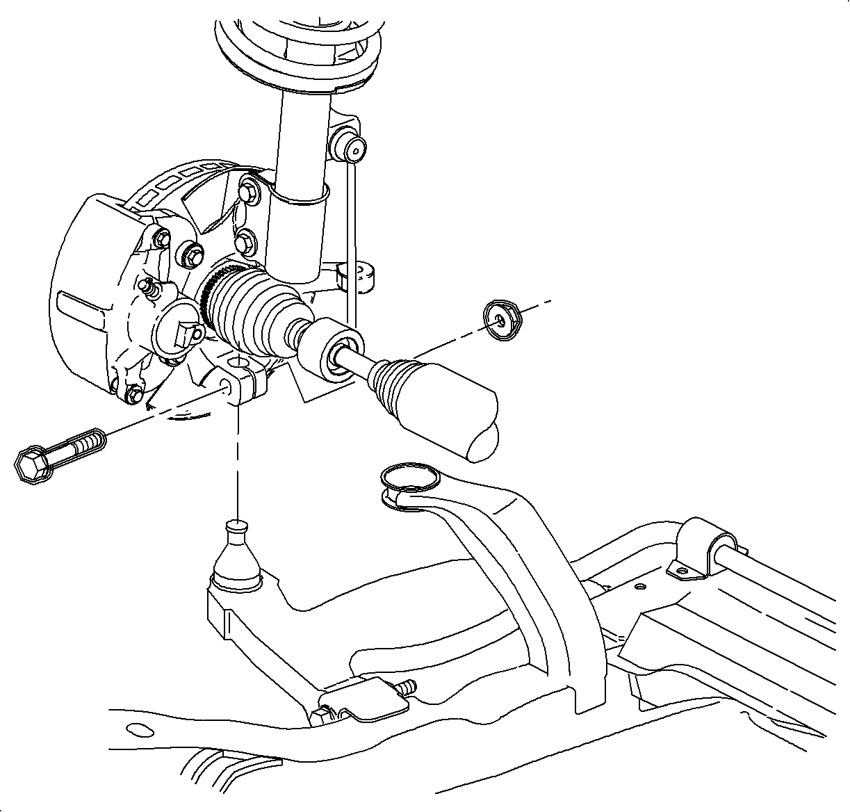
Important: If difficulty is encountered in separating the axle from the hub, tap on the end of the drive axle, using a block of wood and a hammer. Do not hammer directly on the end of the axle.
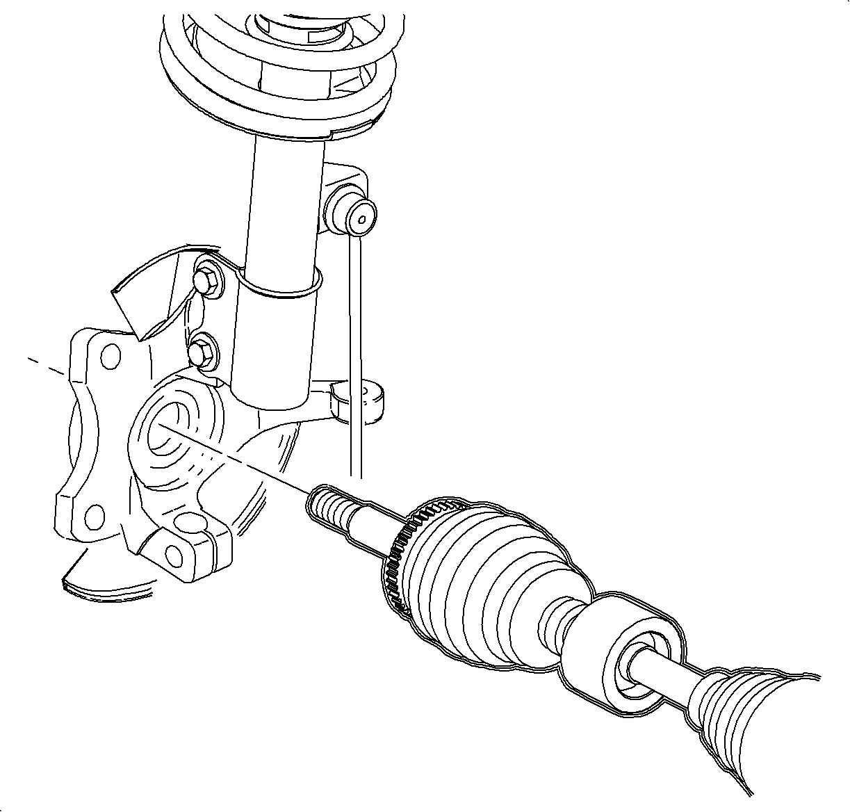
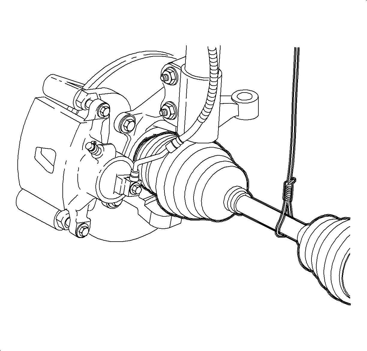
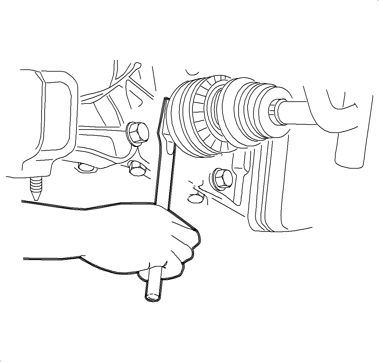
Important: Before removing the drive axle, place an approved container under the transaxle to catch any fluid spillage.

Installation Procedure
- Install a new axle or stub shaft retaining ring.
- Insert the drive axle into the transaxle.
- After the drive axle splines have safely passed the transaxle oil seal, remove the seal protector and fully seat the drive axle into the transaxle.
- Insert the outer end of the drive axle into the wheel hub. Install the drive axle to hub washer and the new nut.
- Install the lower control arm ball stud into the steering knuckle. Hold the bolt stationary and tighten the nut.
- Install the tie rod end into the steering knuckle.
- Using the J 44015 , or equivalent, seat the tie rod end into knuckle.
- Inspect the boot for damage and replace any part if damaged.
- Remove the linkage installer and install the NEW tie rod end nut.
- Install the wheel and tire assembly . Refer to Tire and Wheel Removal and Installation in Tires and Wheels.
- Lower the vehicle from the hoist.
- Tighten the axle shaft to hub nut in the following sequence.
- Install the cotter pin.

Important: Apply output shaft lubricant Saturn P/N 7847638 to the splines of the output shaft before installation.
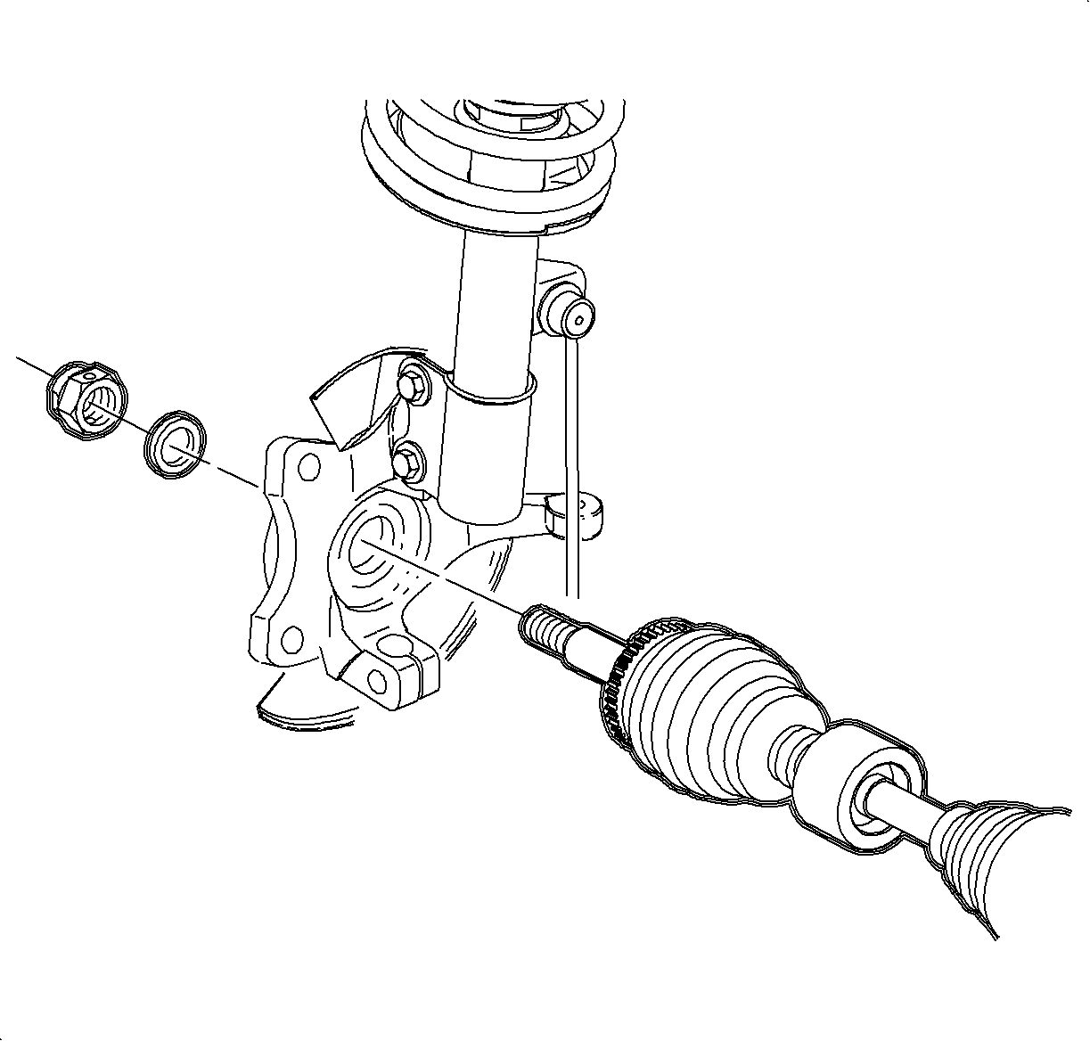
Important:
• Use a new nut. The torque retention of the old nut may not be sufficient. • Do not tighten the fastener at this time.
Notice: Refer to Fastener Notice in the Preface section.

Important: Use a new nut and bolt. The torque retention of old fasteners may not be sufficient.
Tighten
Tighten the lower control arm-to-steering knuckle to 100 N·m (75 lb ft).
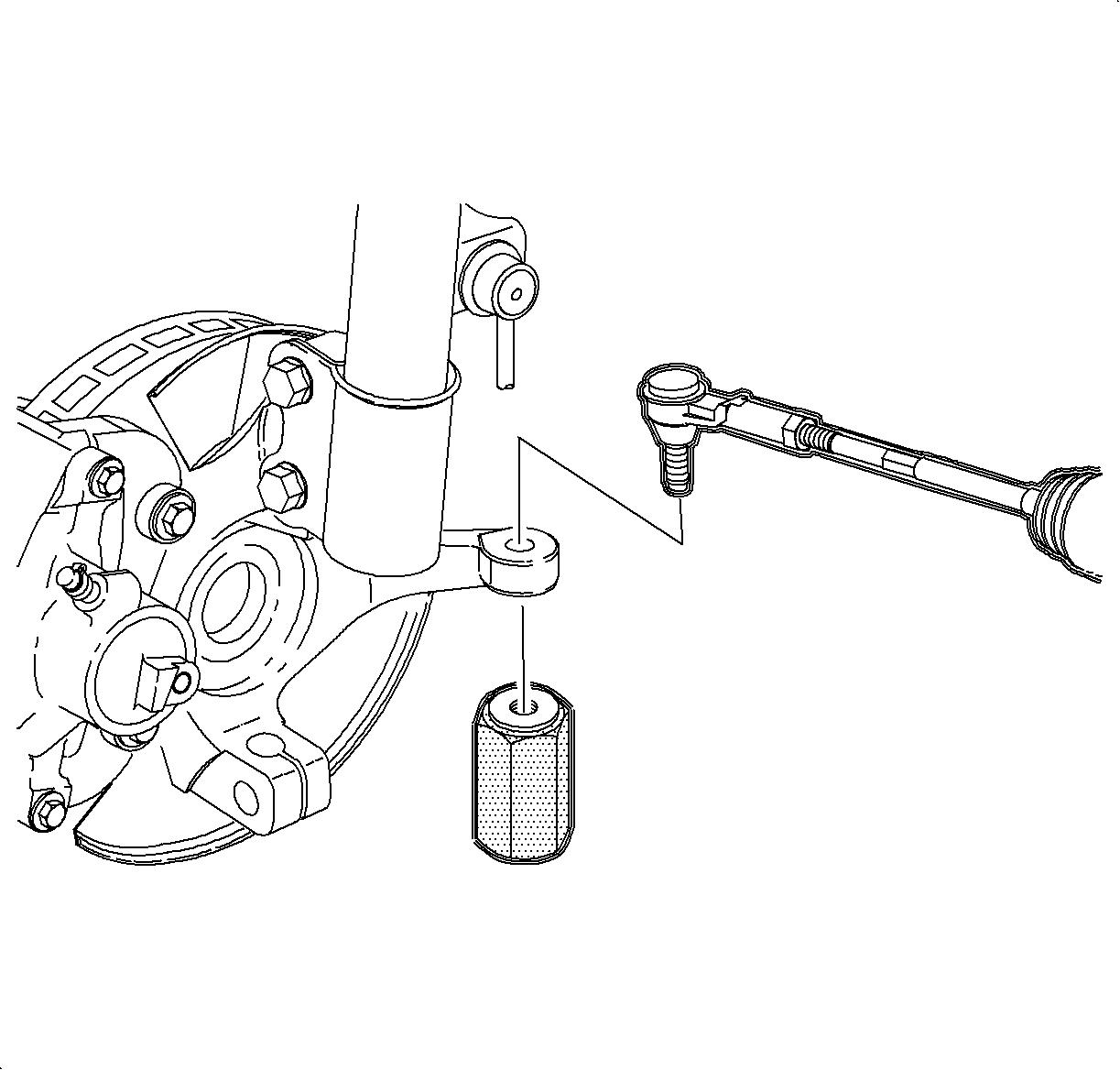
Important: The tie rod ends must be thoroughly cleaned before installing and tightening.
Tighten
Tighten the tie rod end linkage installer to 45 N·m (33 lb ft).
Important: Use a new nut. The torque retention of the old nut may not be sufficient.

Tighten
Tighten the tie rod end-to-steering knuckle nut to 60 N·m (44 lb ft).

Tighten
| • | Tighten the axle shaft-to-hub -- initial torque to 100-160 N·m (74-118 lb ft) then release nut until it is free to turn by hand. |
| • | Tighten the axle shaft-to-hub -- final torque to 20 N·m (15 lb ft) + 90 degrees. If required, continue turning nut until a hole for the cotter pin is aligned properly. |
