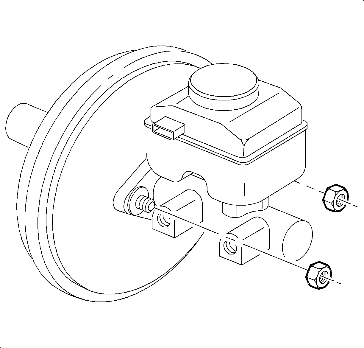
For 1990-2009 cars only
Removal Procedure
- Vehicles equipped with manual transaxles must disconnect the clutch hydraulic feed line from the master cylinder reservoir. Plug the line to avoid leakage and contamination.
- Remove the low brake fluid sensor electrical connector.
- Remove the brake pipe fittings from the master cylinder.
- Remove the master cylinder to brake booster nuts.
- Remove the master cylinder.
Caution: Refer to Brake Fluid Irritant Caution in the Preface section.
Notice: Refer to Brake Fluid Effects on Paint and Electrical Components Notice in the Preface section.

Important: After removing brake pipe nuts, do not excessively pull or bend brake pipes away from master cylinder.
Important: Plug open brake pipes to prevent brake fluid loss and contamination.

Important: Do not bend brake pipes.
Installation Procedure
- Position the master cylinder onto the booster studs and install the nuts.
- Position the brake pipes into the master cylinder and tighten the nuts.
- Vehicles equipped with manual transaxles must install the clutch hydraulic feed line to the master cylinder.
- Connect the low brake fluid switch electrical connector.
- Fill the brake fluid reservoir with clean brake fluid up to the MAX mark on the reservoir.
- Bleed the brake system. Refer to Hydraulic Brake System Bleeding .
Notice: Refer to Fastener Notice in the Preface section.

Tighten
Tighten the cylinder-to-brake booster nuts to 25 N·m
(18 lb ft).

Important: Do not bend brake pipes.
Tighten
Tighten the brake pipe-to-master cylinder nuts to
16 N·m (12 lb ft).

Notice: Refer to Brake Fluid Caution in the Preface section.
