Removal Procedure
- Remove the accessory drive belt from compressor clutch pulley by rotating belt tensioner clockwise using a 14 mm or 9/16 in wrench. Snap-on tool S8190A (or equivalent) can be used.
- Disconnect the A/C compressor clutch electrical connector.
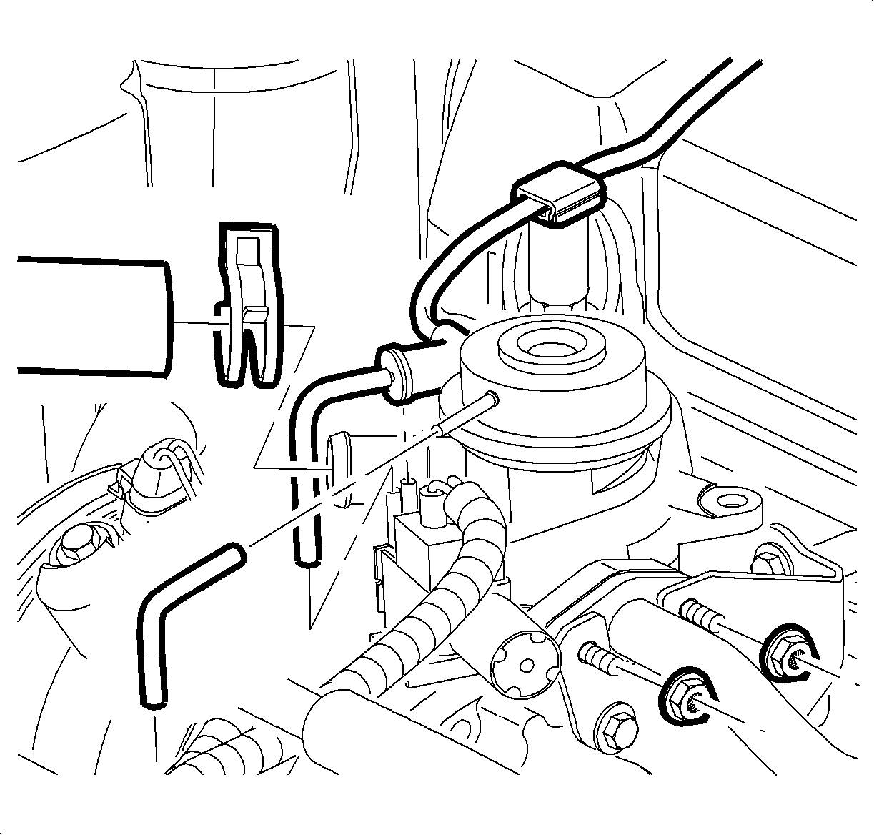
- Remove the nuts from the combination valve studs.
- Remove the air hose.
- Remove the vacuum source hose. (There is no need to disconnect the internal vacuum hose for this procedure.)
- Remove the combination valve and gasket from the rear air compressor bracket.
- Position the combination valve and gasket away from the A/C compressor bracket.
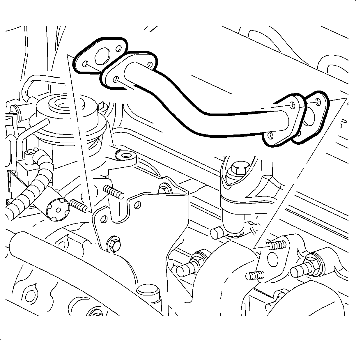
- Remove the air pipe nuts from the exhaust manifold studs.
- Remove the air pipe.
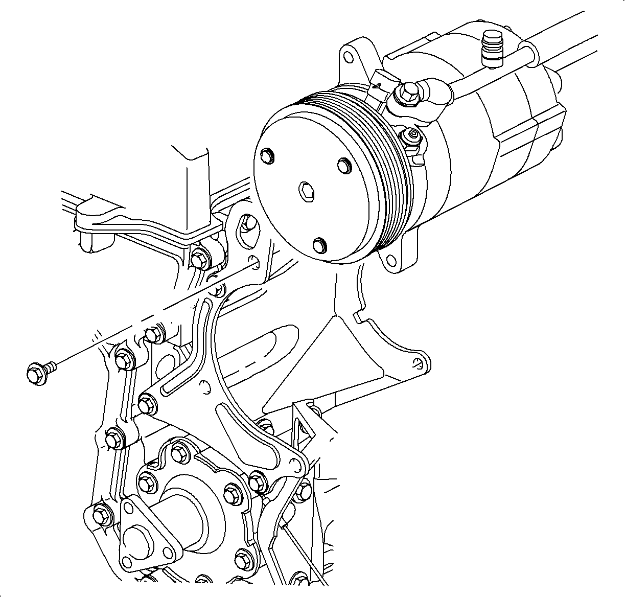
- Remove the rear A/C compressor-to-engine bracket bolts.
- Remove the front A/C compressor-to-engine bracket bolts.
- With A/C lines still attached, lift the A/C compressor upward and install one front bolt through the front engine bracket top hole and the bottom rear mounting ear of A/C compressor. Tighten the bolt so that the A/C compressor is supported by the bracket.
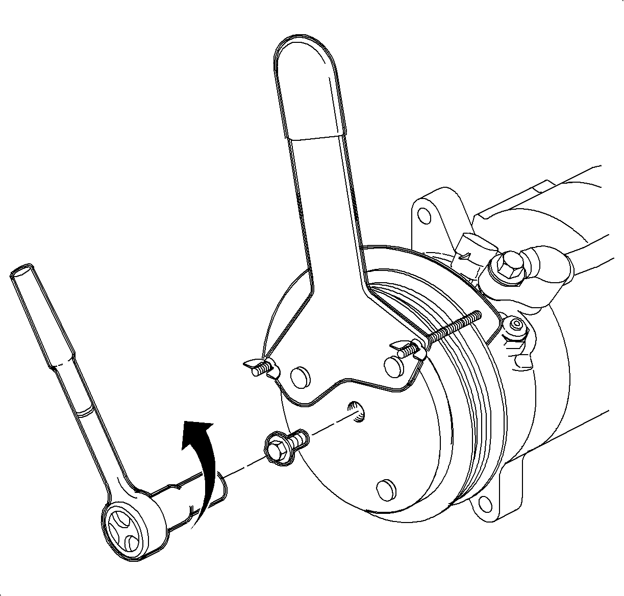
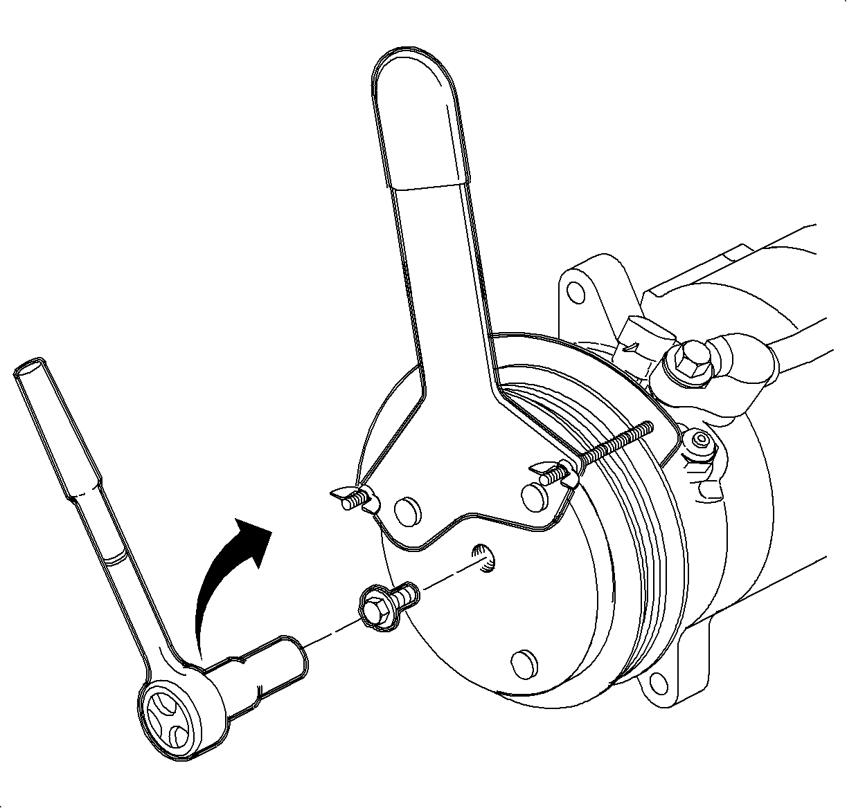
- Install the clutch drive plate holder tool SA9510AC, and remove the drive plate center bolt.
- Remove the drive plate holder tool and completely thread the clutch drive plate remover sleeve SA9506AC into the center of the drive plate.
- Thread the drive plate remover bolt into the sleeve. While holding the clutch drive plate remover sleeve, tighten the drive plate remover bolt to remove drive plate.
- Using the external snap ring pliers, remove the snap ring.
- Position the puller center tool SA9149AC-2 on the end of the A/C compressor shaft.
- Install the three-jaw puller on A/C compressor pulley. Tighten the center bolt to remove pulley assembly.
- Remove three A/C compressor clutch coil screws and remove A/C compressor clutch coil.
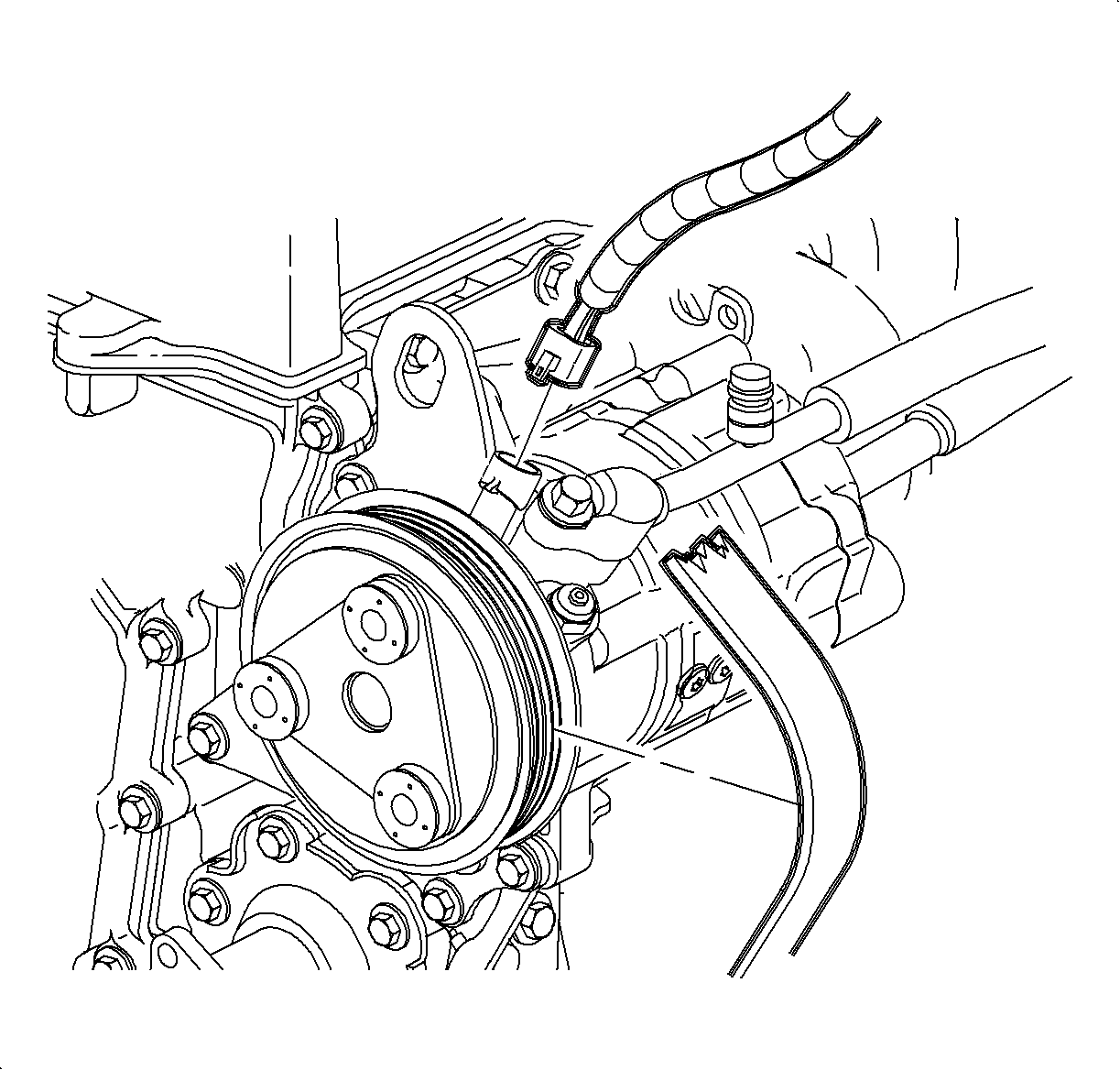
Important: It is not necessary to discharge the A/C system to service the A/C compressor clutch

Important: Steps 3 through 9 are only necessary if the vehicle is equipped with secondary air pump reaction system (AIR).
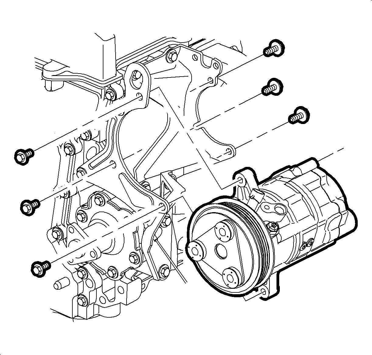
Notice: Ensure that A/C discharge line does not change position and/or loosen at the condenser connection due to moving discharge line. Failure to ensure a tight connection will result in a system refrigerant leak.
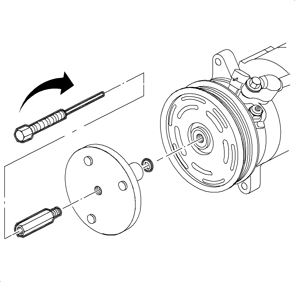
Important: Be careful not to lose the shims when removing drive plate from the compressor shaft.


Notice: Do not remove pulley without puller adapter. If A/C compressor shaft is pressed on, A/C compressor will be damaged.
Important: Make sure to hook the puller jaw behind the pulley.

Important: To enable easier removal of the screws, lightly tap on the end of the screwdriver with a plastic hammer.
Installation Procedure
- Position the A/C compressor clutch coil so that the electrical connector is aligned with indent in the compressor front head.
- Install three A/C compressor clutch coil screws.
- Place the thrust bearing and the drive plate installer SA9149AC-3 on the installation bolt and insert through the center of the pulley. Thread the installation bolt into the end of the A/C compressor shaft and finger tighten.
- Finger tighten the nut on installation bolt to align pulley to A/C compressor. While holding end of bolt, tighten nut until pulley bottoms out on A/C compressor.
- Loosen the nut and remove the pulley installation bolt.
- Install the snap ring with the tapered side out using the snap ring pliers.
- Place the thrust bearing on the installation bolt. Insert the installation bolt through the drive plate.
- Install the shims removed from the old drive plate over the end of the installation bolt. Make sure to install the same number of shims that were removed.
- Thread the installation bolt into the A/C compressor shaft.
- While holding the end of the installation bolt, tighten the nut to the press drive plate onto A/C compressor shaft. Tighten until the drive plate bottoms out.
- Loosen the installation bolt nut and remove installation bolt.
- Install the clutch drive plate holder tool SA9510AC.
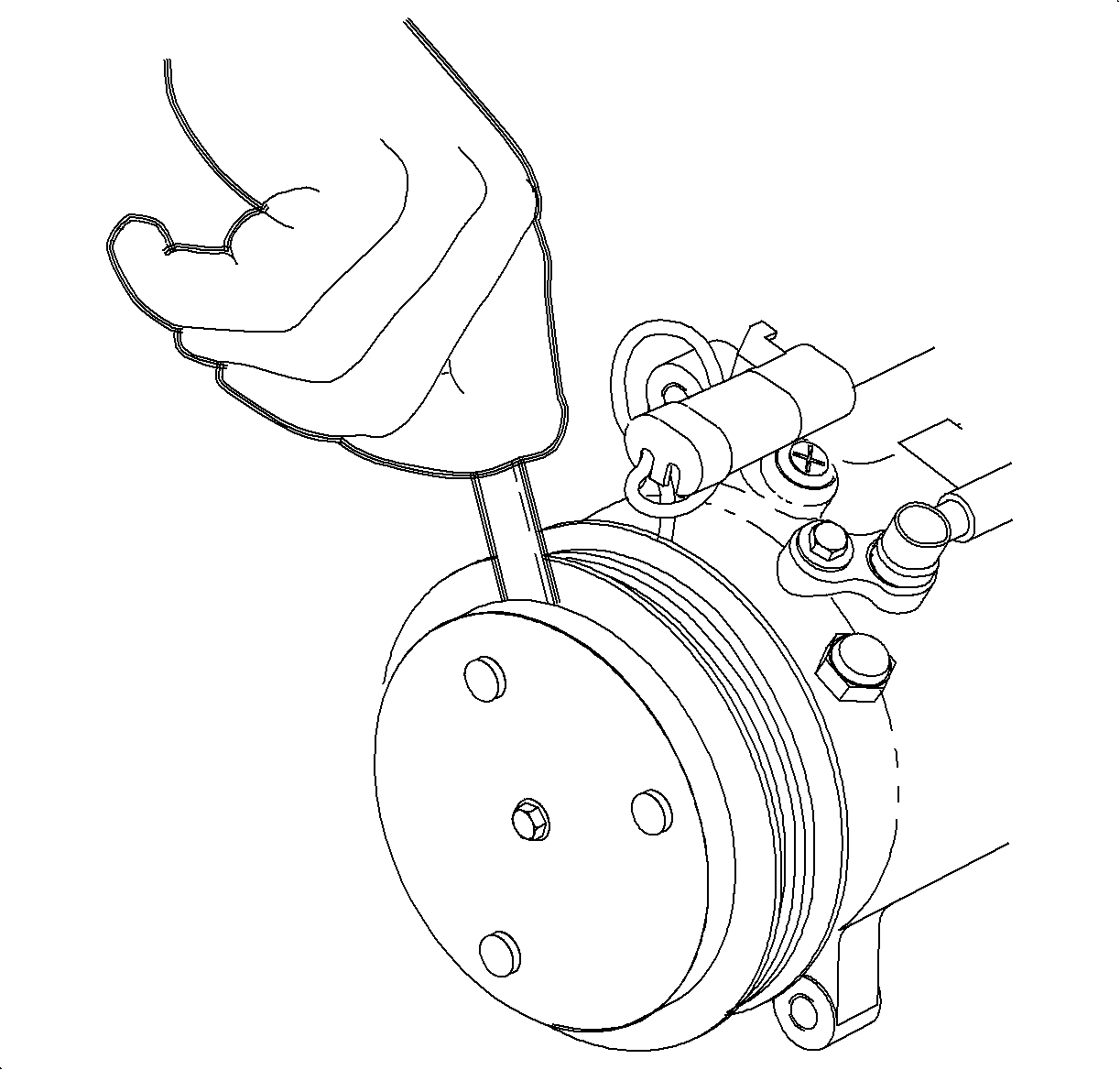
- Install the center bolt and tighten.
- Check to make sure the clutch clearance is 0.5 mm-0.7 mm (0.018 in-0.030 in).
- If necessary, adjust the clearance by adding shim(s) provided. Refer to steps 6 through 8 of the removal procedure to remove the drive plate, then after installing the shims refer to steps 7 through 14 to install the drive plate.
- Remove the front bracket-to-compressor bolt and position the A/C compressor between the brackets.
- Install the A/C compressor to front bracket with three bolts. Finger tighten the bolts.
- Install the A/C compressor to rear bracket with three bolts. Tighten the front and rear bolts.
- Install the air pipe onto the exhaust manifold studs.
- Install the air pipe into the rear air compressor bracket slot.
- Install the combination valve studs into the rear air compressor bracket through air pipe flange holes.
- Install and tighten the nuts on the combination valve studs.
- Install and tighten the nuts on exhaust manifold studs.
- Install the vacuum source hose.
- Install the air hose.
- Connect the A/C compressor clutch electrical connector.
- Install the accessory drive belt
- Start the engine and engage the A/C compressor 10-15 cycles to break-in new a/C compressor clutch. This cycling of the A/C compressor will match the drive plate and pulley surfaces.

Tighten
Tighten to 5 N·m (44 lbs in)


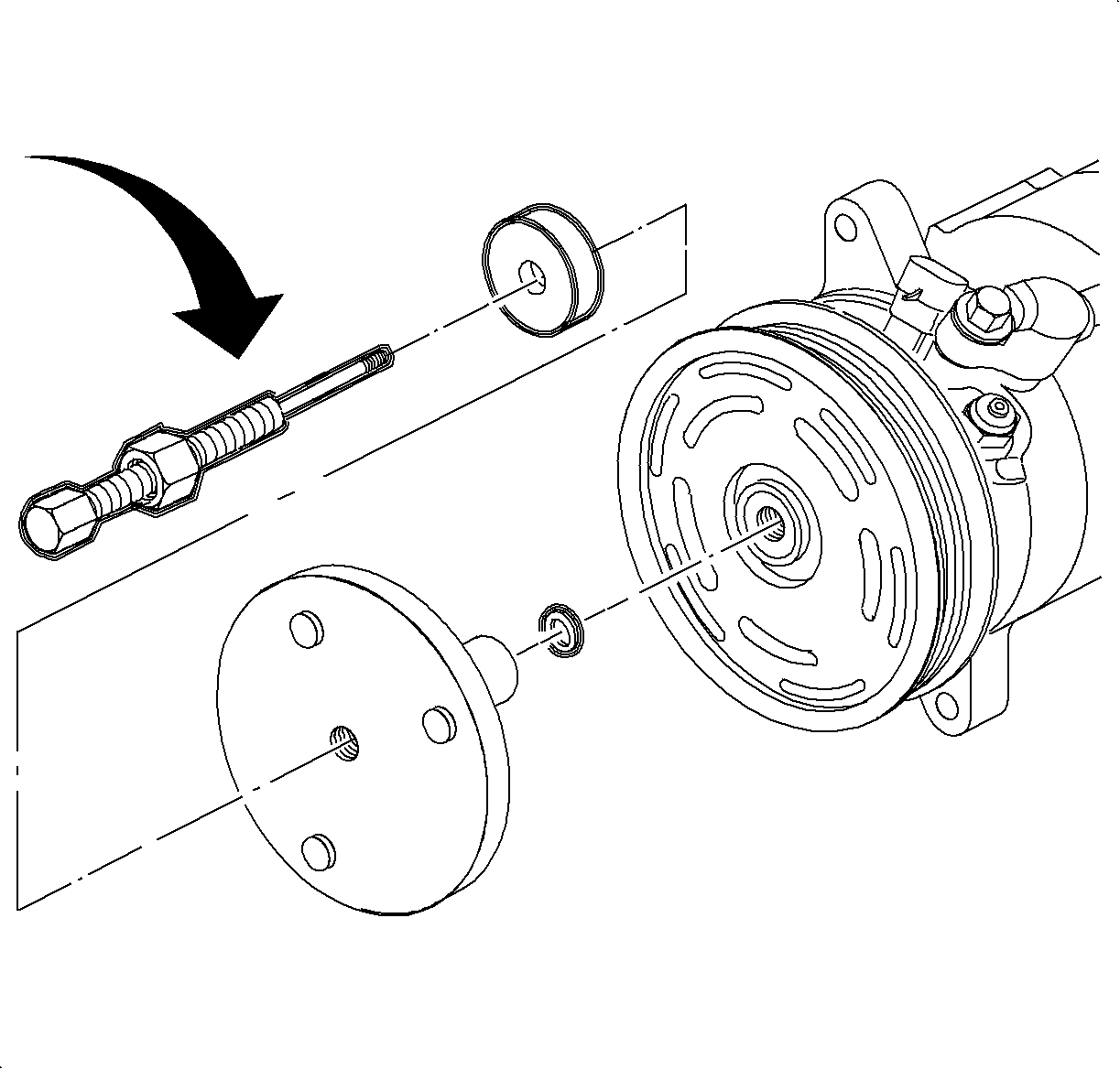
Important: Make sure the splines are engaged by rotating the drive plate back-and-forth before the tightening nut.
Tighten
Tighten to 13 N·m (115 lbs in)
Important: After tightening the center bolt, check to make sure that the pulley rotates smoothly by spinning it.

Tighten
Tighten the front bolts to 49 N·m (36 lbs ft)
Tighten
Tighten the rear bolts to 25 N·m (19 lbs ft)

Notice: Make sure gaskets are installed correctly or a leak will occur. If gaskets are removed from stubs, replace with new gaskets. Installation steps must be performed in sequence.
Important: Steps 19 through 25 are only necessary if the vehicle is equipped with secondary air pump reaction system (AIR).
Tighten
Tighten to 7 N·m (62 lbs in)
Tighten
Tighten to 7 N·m (62 lbs in)
