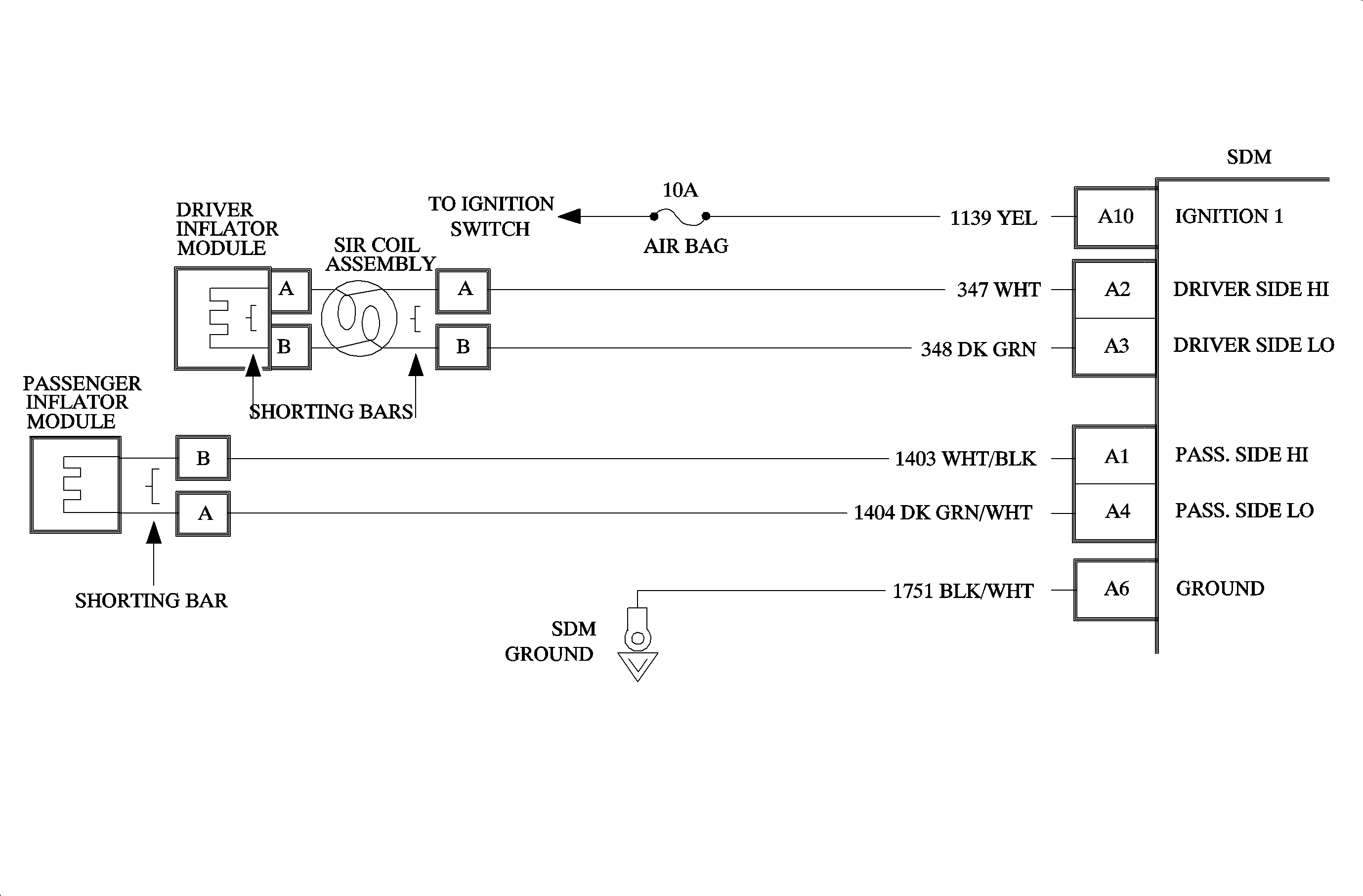
Circuit Description
When the ignition switch is first turned ON, the SDM will perform tests to diagnose critical malfunctions within itself. Upon passing these tests "Ignition 1", VLR, and deployment loop voltages are measured to ensure they are within their respective normal voltage ranges. The SDM monitors the voltage at "Driver Side LO" terminal A3 and "Passenger Side LO" terminal A4 to detect shorts in ground in the inflator module circuits.
DTC Will Set When
The VLR power supply in the SDM is in it's normal operating voltage range and at least one of the two inflator modules is not open. Then, if the voltage measured at "Driver Side LO" is less than or equal to 3 volts and the voltage measured at "Passenger Side LO" is greater than 3 volts for 500 milliseconds during "Continuous Monitoring" or "Current Source Diagnostics," DTC B1024 will set.
Action Taken
SDM turns ON the AIR BAG telltale lamp and sets, DTC B1024, and also DTC B1071. DTC B1024 will take precedence over DTC's B1021 and B1022.
DTC Will Clear When
The fault condition is removed and the SDM is replaced. DTC B1024 will remain current, regardless if the ignition switch is turned OFF or a Scan tool "Clear Codes" command is issued, until the faulty wiring or component is repaired or replaced and the SDM is replaced.
Diagnostic Aids
It is critical to diagnose all circuitry before replacing the SDM. If the malfunction still exists, the new SDM will be damaged. An intermittent condition is likely to be caused by a short to ground in the driver inflator module circuits. Inspect circuits 347 and 348 carefully for cutting or chafing. If the wiring pigtail of the SIR coil assembly or the driver inflator module is damaged, the component must be replaced. If no wiring or component failures are diagnosed, after a complete and thorough inspection, the fault may have occurred internally to the SDM.
The test for this diagnostic trouble code is run during "Continuous Monitoring" and "Current Source Diagnostics", unless DTC B1017 or DTC B1026 is detected.
When measurements are requested in this chart use SA 91114NE DVM with correct terminal adapter from SA 9206Z. When a check for proper connection is requested refer to Intermittent and Poor Connections. When a wire connector or terminal repair is requested, use the proper repair parts and refer to Wiring Repairs .
Caution: Be careful when you handle a sensing and diagnostic module (SDM). Do not strike
or jolt the SDM. Before applying power to the SDM:
• Remove any dirt, grease, etc. From the mounting surface. • Position the SDM horizontally on the mounting surface. • Tighten all of the SDM fasteners and SDM bracket fasteners to the specified
torque value.
DTC Chart Test Description
The numbers below refer to the step numbers on the diagnostic table.
-
This test determines whether the malfunction is occurring in the driver inflator module, coil assembly, or the circuitry.
-
This test determines whether the malfunction is due to the driver inflator module or the coil assembly.
-
This test checks for a short from the "Driver Side HI" to ground.
-
This test checks for a short from "Driver Side LO" to ground, or an SDM integrity problem.
Step | Action | Yes | No |
|---|---|---|---|
1 | Did you perform the Diagnostic System Check - SIR? | Go to Step 2 | |
2 |
Is the Driver Sense LO voltage less than 3.3 volts? | Go to Step 4 | Go to Step 3 |
3 |
Is the Driver Sense LO voltage less than 3.3 volts? | Go to Step 5 | Go to Step 9 |
4 |
Does DVM display OL (Infinite)? | Go to Step 6 | Go to Step 7 |
5 |
Go to Step 10 | -- | -- |
6 | Measure resistance on the SDM harness connector from terminal A3 to terminal A6 (ground). Does DVM display OL (Infinite)? | Go to Chart A | Go to Step 8 |
7 | Repair short from circuit 347 to ground. Go to Step 10 | -- | -- |
8 | Repair short from circuit 348. Go to Step 10 | -- | -- |
9 |
Go to Step 10 | -- | -- |
10 |
Repeat SIR Diagnostic System Check. | -- | -- |
