Service Manual Update for Audible Warnings Diagnostic Information and Wiring Schematics in the 1998-1999 Electrical Service Manual

| Subject: | Service Manual Update for Audible Warnings Diagnostic Information and Wiring Schematics in the 1998-1999 Electrical Service Manual |
| Models: | 1998-1999 Saturn vehicles |
Purpose:
The purpose of this bulletin is to provide service manual pages that were omitted in the 1998-1999 Electrical Service Manual.
The pages included in this bulletin make up section 76- Audible Warnings (Chime). Copies of these pages should be made and inserted between sections 64 and 81 of the 1998-1999 Electrical Service Manuals at Saturn Retailers.


Diagnosis
Fuse | Location | Type | Feeds | -- | ||||||
|---|---|---|---|---|---|---|---|---|---|---|
IGN4 Fuse | Underhood junction block | 30 A Maxifuse | Circuit 202 | If the vehicle starts, the fuse is good. If the fuse is blown determine the cause of the blown fuse and repair. Replace the fuse as needed. | ||||||
Chime Fuse | Instrument panel junction block |
10 A Minifuse | Circuit 440 | If the following system is operating normally, the fuse is most likely good:
If the fuse is blown determine the cause of the blown fuse and repair. Replace the fuse as needed. | ||||||
IGN1 Fuse | Instrument panel junction block | 10 A Minifuse | Circuit 39 | If the following system is operating normally, the fuse is most likely good:
If the fuse is blown determine the cause of the blown fuse and repair. Replace the fuse as needed. |
Grounds
Before checking the ground circuit from the faulty component all the way to the ground stud, check the circuit from the splice pack ground by testing some of the other subsystems grounded by the same splice pack. If the other subsystems function properly, it is most likely that the path from the splice pack to ground is good (or at least one of the paths is good with redundantly grounded splice packs.
Splice Pack | Location | -- | ||||||||||
|---|---|---|---|---|---|---|---|---|---|---|---|---|
I/P Splice Pack #1 | Taped to the harness behind the I/P cluster. | The systems grounded by the I/P Splice Pack #1 are grounded redundantly with Splice Pack #2 at ground point location D (I/P chassis ground). If one of the following systems is operating normally, the ground circuit is most likely good.
Check for OPENS/SHORTS. Repair as needed. | ||||||||||
I/P Splice Pack #2 | Taped to the harness behind the I/P cluster. | The systems grounded by the I/P Splice Pack #2 are grounded redundantly with Splice Pack #1 at ground point location D (chassis ground). If one of the following systems is operating normally, the ground circuit is most likely good.
Check for OPENS/SHORTS. Repair as needed. | ||||||||||
ABS/SIR Splice Pack (1998 only) | Taped to the harness behind the I/P cluster. | If one of the following systems is operating normally, the ground circuit is most likely good.
Check for OPENS/SHORTS. Repair as needed. If this component is good, go to the next item indicated on the chart. | ||||||||||
Left Body Ground Splice Pack | Left side under the drivers seat | The left side body splice pack provides a ground path for the left side body harness. The left body ground splice pack has an integral ring terminal that grounds the splice pack directly to the body of the vehicle. If one of the following systems is operating normally, the ground circuit is most likely good.
Check for OPENS/SHORTS. Repair as needed. |
Components:
Component | -- |
|---|---|
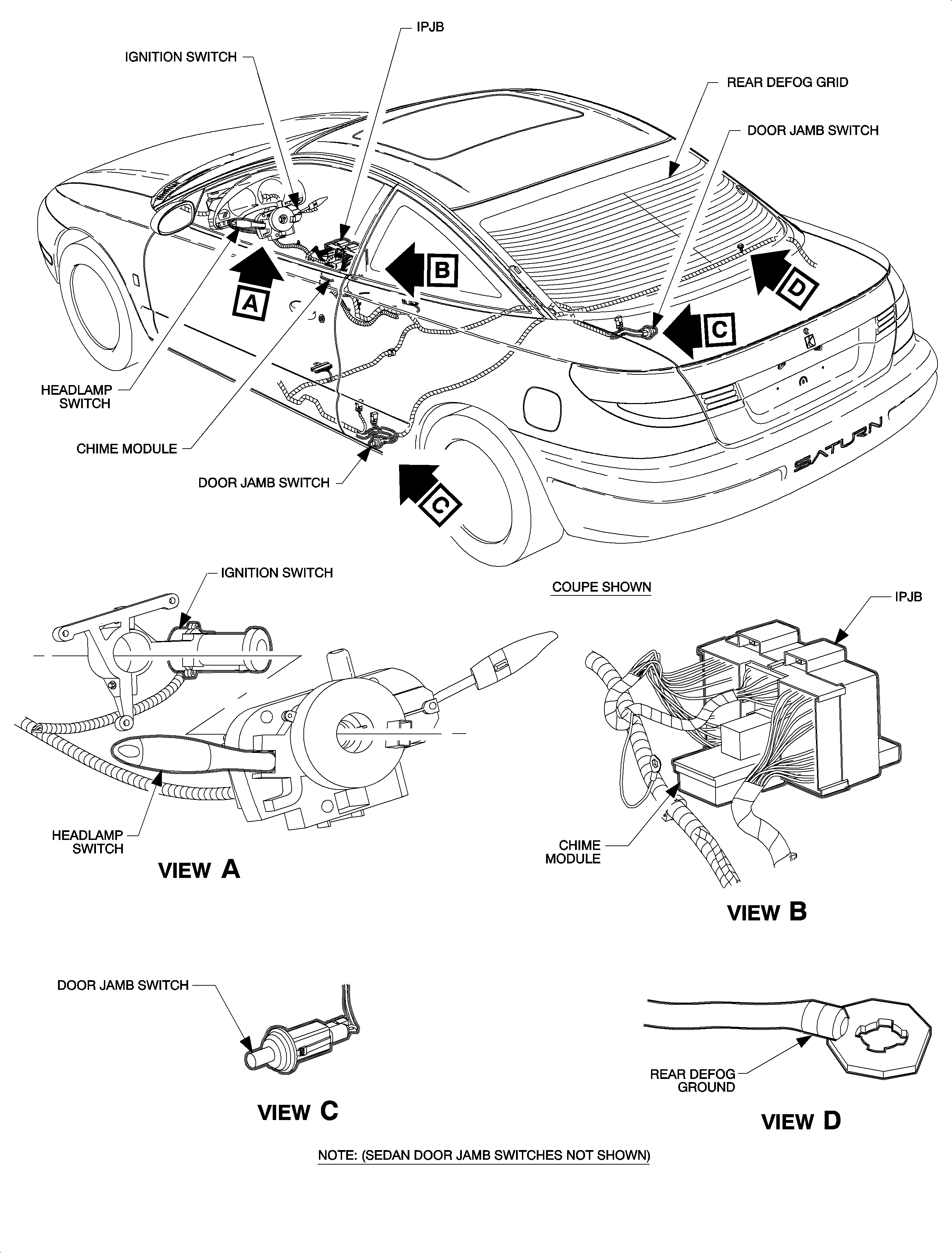
Chime Module | Location: Plugs into the back of the instrument panel junction block. Remove the access panel on the drivers side of the instrument panel junction block. Check the condition of the pins on the chime module and the junction block. Straighten any bent pins. The chime module is not repairable. If the other components of the system operate normally, install a new chime module. If the problem is corrected re-install the old chime module to verify the problem is the chime module. |
Key Minder Switch -- Inside the ignition Switch | Check Switch resistance. Switch resistance: OPEN with KEY OUT, the key has been turned to ACC less than 1 ohm with KEY IN: once Repair/Replace as needed. |
river Seat Belt Switch | Check the switch resistance Switch resistance: Open with the drivers lap belt buckled, less than 1 ohm with the belt unbuckled. Repair/Replace as needed. |
Rear Defog Relay | All junction block relays, except ABS and door lock, are interchangeable. Substitute another relay from either junction block to see if the problem is fixed. Repair/Replace as needed. |
Headlamp Switch | Refer to Lever Combination Switch (LCS) section 160, in this manual for testing. Repair/Replace as needed. |
I/P Cluster | Refer to Audio System and I/P Cluster service manual for diagnostic information, and removal and installation procedures for internal cluster components. |
Seatbelt Telltale | If the driver's belt is not buckled, the seatbelt telltale will come on and stay on for 7 seconds. If the driver's belt is not buckled after 7 seconds, the light will remain ON for an additional 13 seconds followed by 100 seconds of flashing. If the driver's belt is buckled at any time after the initial 7 second period, the telltale will be immediately turned OFF. Inspect the seatbelt telltale cluster bulb. Replace a needed. |
Door Jamb/Ajar Switch | Check the switch resistance. Switch resistance: OPEN with the door closed, less than 1 ohm with the door open. Repair/Replace as needed. |
Sensing and Diagnostic Module (SDM) | Refer to the SIR service manual. |
General Description
Chime
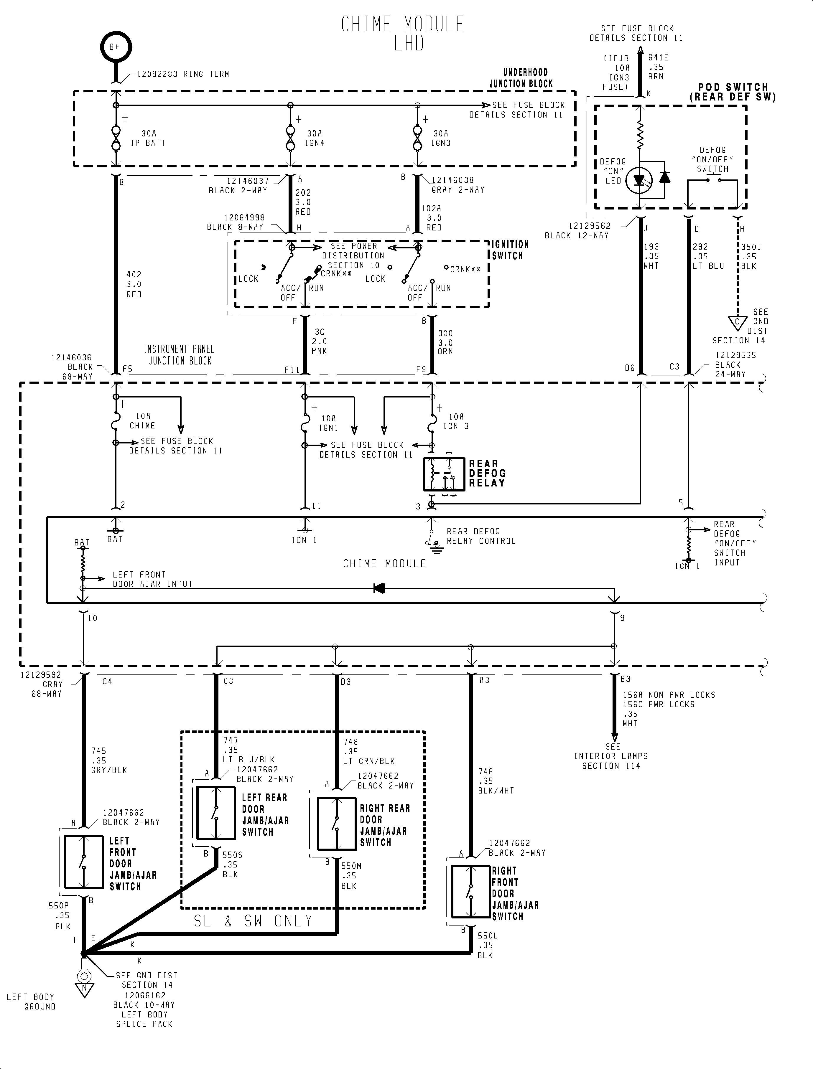
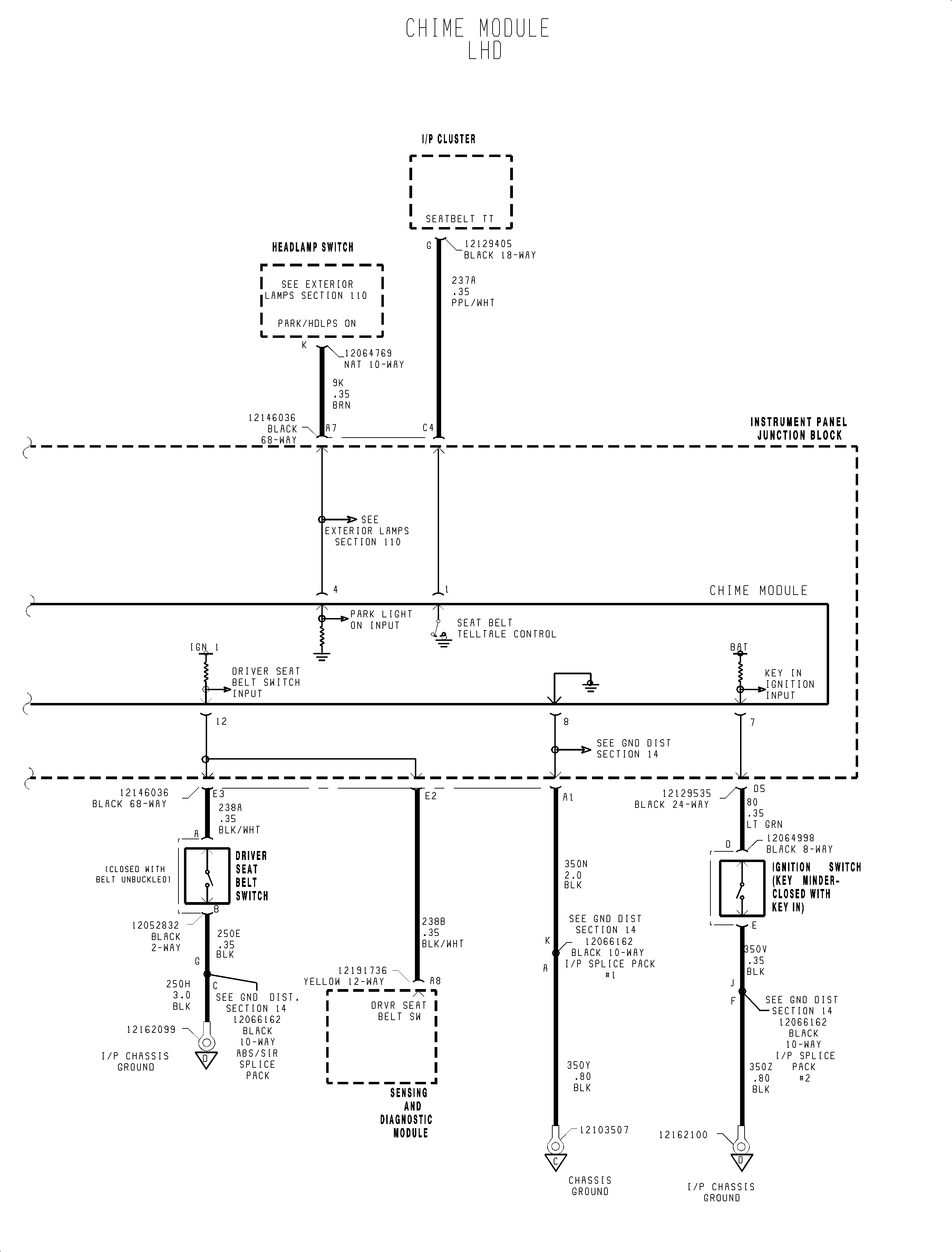
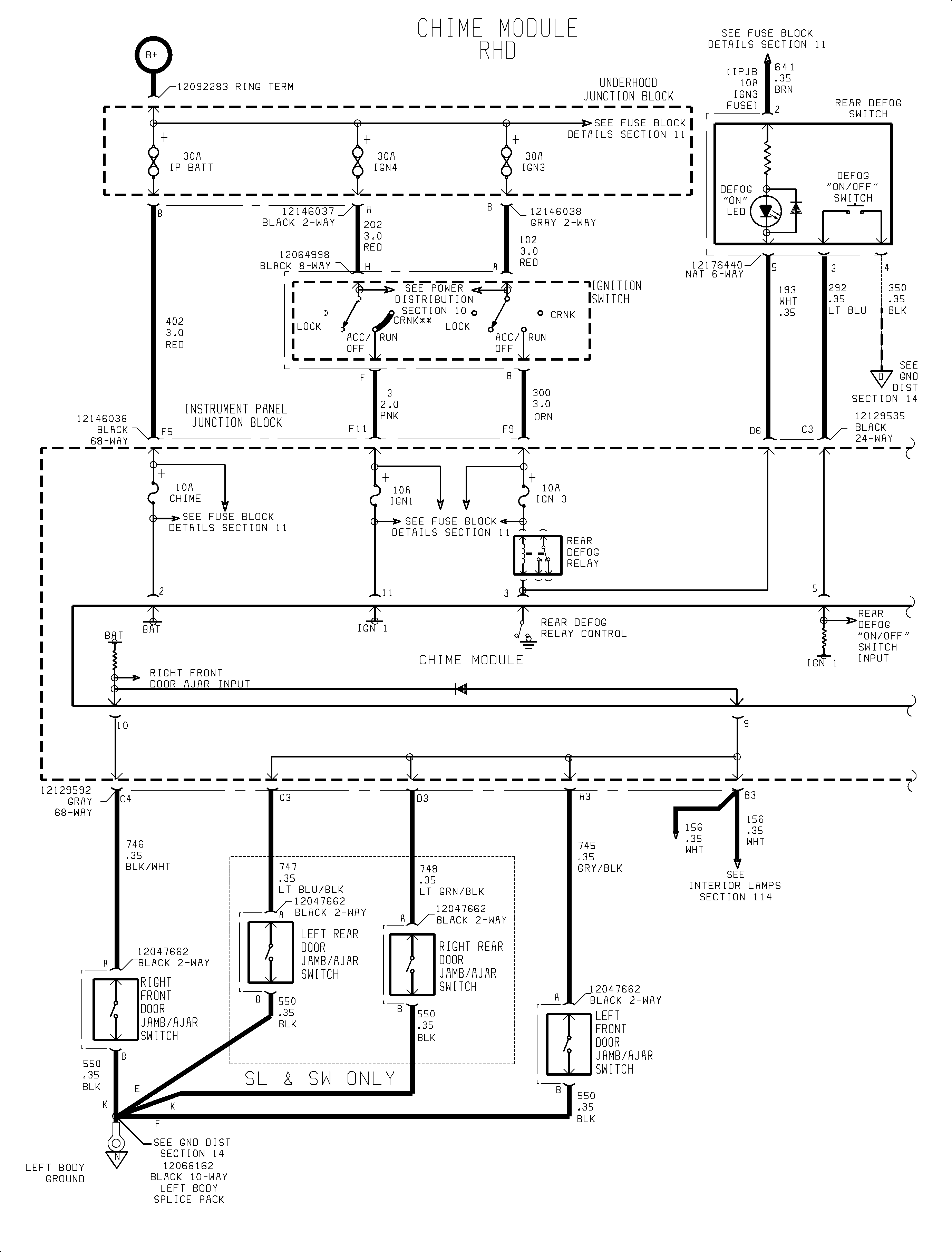
The chime module has several vehicle functions including audible warnings for an unbuckled driver seat belt, key-in-ignition reminder and a lights-on reminder. The chime also controls the rear defog system and the seatbelt telltale. The chime system consists of a chime module, located in the instrument panel junction block, and various switches and components which provide inputs to or receive outputs from the chime module.
Chime Audible Operation
The chime sound consists of repetitive pulses of a 1,000 Hz tone. The amplitude of each pulse decays gradually, as opposed to an abrupt beeping sound. The following repetition rates distinguish the various reminders:
| • | Seat belt -- 50 cycles per minute |
| • | Key-In -- 120 cycles per minute |
| • | Lights-On -- 180 cycles per minute |
Some audible warnings take precedence over others. The following is the list of audible warnings in order of precedence:
- Seat Belt Audible
- Key Minder Audible
- Lights on Audible
Seat Belt Audible
The chime module provides an audible reminder (5 chimes over 8 seconds) in the event of the following condition:
The ignition key is in the RUN position, and the driver's seat belt is unbuckled.
Key minder Audible
The chime module provides an audible warning if the driver's door is open, the key is in the ignition and the conditions outlined in the following chart are present. The following chart assumes that the ignition switch is moved through the positions in the listed order.
Key in LOCK position | No Audible |
Key in ACC position | Audible |
Key in RUN position | No Audible |
Key in START position | No Audible |
Key in RUN position | Audible |
Key in ACC position | No Audible |
Key in LOCK position | Audible |
The chime provides a one second delay when the ignition switch is moved through the ACC position during normal starting of the vehicle, and the driver's door is open. After the one second delay, the audible is heard.
Light Minder Audible
The chime module provides an audible warning if the park lamps or headlamps are on, and the driver's door is open and one of two conditions exist: The key is out of the ignition switch, or the key is in the ignition at the LOCK position and has not been turned. In addition, if a condition exists calling for both the key minder audible and the lights on minder audible, the key minder audible takes priority.
Chime Inputs/outputs
Door Jamb/Ajar Switch
The door jamb/ajar switch is a plunger type switch mounted in the B-pillar. When the driver's door is opened beyond a prescribed distance, the switch contacts close signalling to the chime module that the door is open. Internal to the chime module the left front door ajar input pin 10 is connected to pin 9, but there is a diode between the two pins which prevents the right front and rear door jamb ajar switches from pulling the left front door ajar input LO. This internal connection allows the left front door jamb/ajar switch to also control the dome lamp.
Ignition and Key Alarm Switch Assembly
The key minder circuit is a set of contacts that are activated by the ignition module mechanical driver. When the switch is closed, the circuit pulls the chime module current input to ground. The ground circuit is provided by a wire ground to switch.
Rear Defog Switch and Timer
The chime module provides the timing function and control of the rear defog system. When the rear defog switch is pressed for the first time in an ignition cycle, the rear defog element and switch indicator will come ON, and stay ON for 15 minutes unless the ignition is turned to either the ACC or LOCK position or the rear defog switch is pressed again to turn the system OFF. Subsequent activations of the switch, prior to cycling the ignition, when the rear defog is OFF, will result in the same operation, except the time the defogger is ON is reduced to 7.5 minutes.
Seat Belt Telltale
The seat belt telltale is used to inform the driver of the vehicle that the driver seat belt has not been buckled. If the belt is buckled prior to the ignition being turned to RUN the telltale will not come on. If the belt is not buckled prior to the ignition being turned to RUN the telltale will come on steady for 20 seconds. if the belt is still unbuckled after this time, the telltale will flash for 10 seconds. If the belt is buckled at any time the telltale will turn OFF immediately.
If the belt is buckled and then unbuckled during a single ignition cycle the above mentioned sequence will begin.
