MIL Illuminated with DTCs P0171 Fuel Trim System Lean and/or P0172 Fuel Trim System Rich

| Subject: | Malfunction Indicator Lamp (MIL) Illuminated with DTCs P0171 Fuel Trim System Lean and/or P0172 Fuel Trim System Rich (Inspect for Evidence of Engine Coolant Around Front Oxygen Sensor Connector and if Necessary Replace Oxygen Sensor and Engine Harness Connector) |
| Models: | 2003 Saturn VUE vehicles equipped with 4 cyl. (L61) engines with engine build date prior to S208060001. |
Condition
Some customers may comment about an intermittent rough idle and/or MIL is illuminated.
Cause
Some early 2003 Saturn VUEs may have been assembled with a slight amount of engine coolant present in the front oxygen sensor connector resulting in fuel trim diagnostic failures. The presence of engine coolant in the oxygen sensor connector may allow cross-talk between the oxygen sensor heater circuits and the sensor signal circuit.
Correction
Once engine coolant contamination of the O2 sensor connector is confirmed, it will be necessary to replace the connector body on the engine harness. For specific instructions refer to the procedure listed in this bulletin.
Diagnostic Procedure
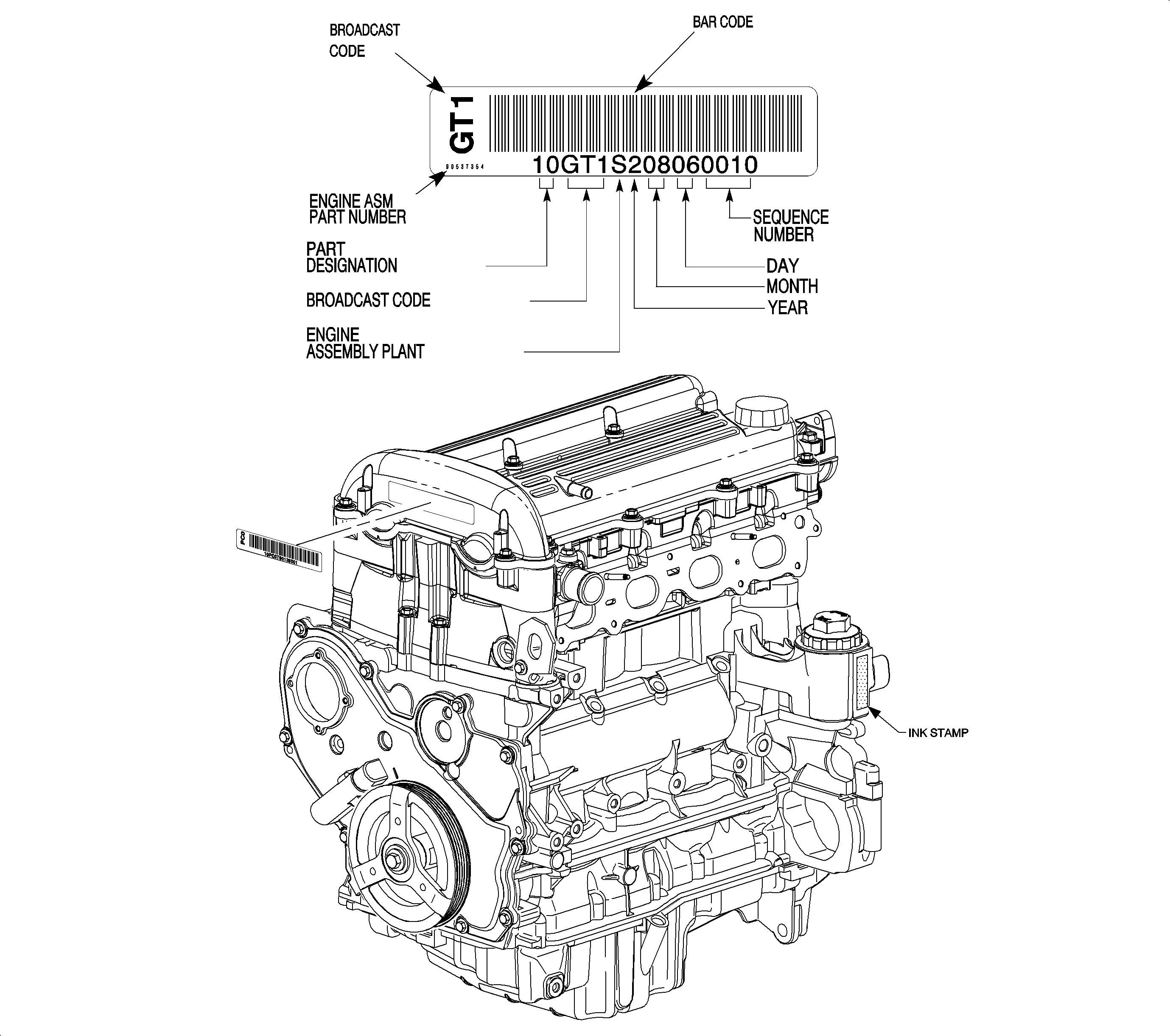
Important: This procedure applies only to engines manufactured in Spring Hill assembly prior to August 5, 2002. Proceed to step 1 and inspect engine code for build date prior to S208060001. This procedure does not apply to engines with assembly plant code T.
- Refer to illustration below and verify built date.
- If DTCs P0171 and P0172 are both present, replace the front oxygen sensor; or if P0130, P0131 or P0132 are present in addition to P0171/P0172, replace the front oxygen sensor. Refer to the procedure listed below.
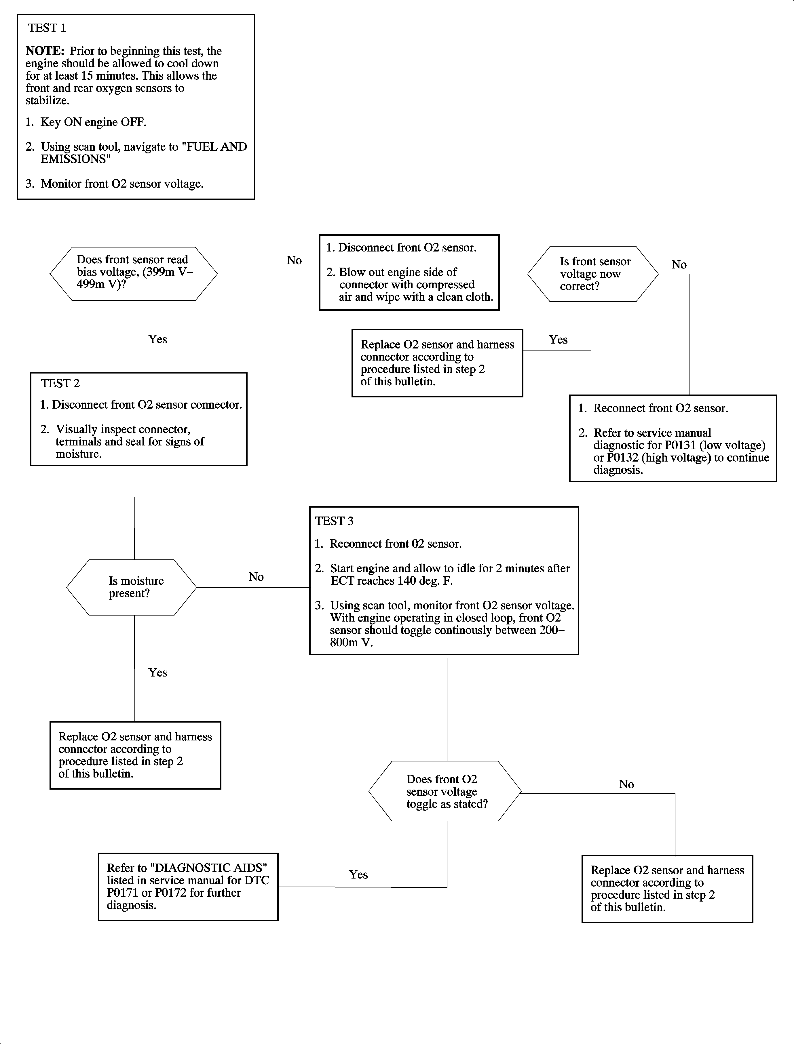
- If P0171 or P0172 are present with no other codes, refer to the diagnostic chart on the following page.

| 2.1. | Disconnect O2 sensor and ECT sensors to allow greater access to the connector. Lift the branch of the harness to provide easier access to the connector body. |
| 2.2. | Using terminal tool #J38125-12A, remove terminals from service part. The terminals are released by inserting the tool into the small notch on the face of the connector adjacent to the terminal then pulling the terminal out from the harness side. Discard the cut leads that are removed from the service replacement part. |
| 2.3. | Remove existing terminals from the vehicle's engine wiring harness. Clean terminals with electronic contact cleaner (CRC 113 or equivalent), then dry with compressed air. |
| 2.4. | Insert existing terminals into new connector housing. Be sure to seat terminal fully into the correct connector cavity. |
* See table at end of steps.

| 2.5. | Reinstall the engine harness to its original routing. Reconnect the ECT sensor and O2 sensor. |
Important: Once the engine wiring harness connector has been replaced, be sure not to plug it back into a contaminated sensor.

*
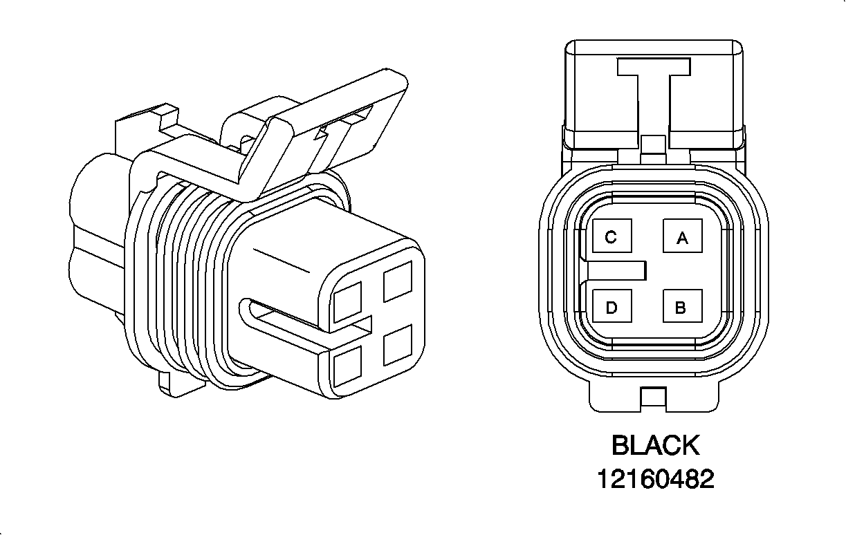
HEATED OXYGEN SENSOR 1 (L61) - 12160482 | ||||
|---|---|---|---|---|
CAVITY | WIRE COLOR | CIRCUIT NUMBER | WIRE SIZE | CIRCUIT FUNCTION |
A | TAN | 1667 | .50 | O2 SENSOR - LO |
B | PPL | 1666 | .50 | O2 SENSOR - HI |
C | DK GRN | 626 | .50 | O2 SENSOR - HEATER |
D | WHT | 5291 | .50 | POWER - UHFB - EMISS |
Location: Rear Engine | Probe: Gray | Tool: 12094429/J38125-12A | ||
Parts Requirements
Part Number | Description |
|---|---|
12568234 | Sensor ASM-HTD OXY (POSN 1) |
21019319 | CONNECTOR-SEN-OXY |
Claim Information
To receive credit for this repair during the warranty coverage period, submit a claim through the Saturn Dealer System for J6372 (Sensor, Oxygen, I4 (L61) - Replace), or if another procedure is performed refer to the appropriate electronic labor time guide. An "add time" condition is provided to replace terminals in engine harness oxygen sensor connector.
