For 1990-2009 cars only
Tools Required
| • | DT 46509 Tube Style Driver |
| • | SA9179NE Dial Indicator |
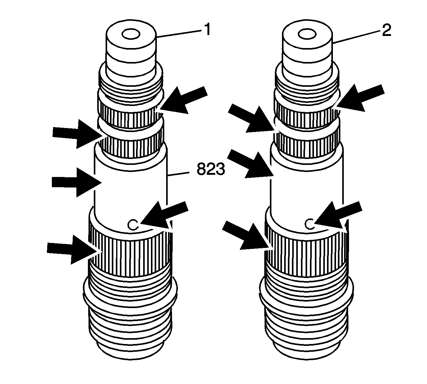
- Inspect the 3rd clutch shaft to determine if the fluid passage hole matches the 1st design or 2nd design. In the 1st design (1) the fluid passage hole diameter is 4.0 mm. In the 2nd design (2) the fluid passage hole diameter is 3.7 mm.
- Wrap the 3rd clutch shaft (823) splines with tape.
- Install 2 new 26.7 mm x 1.9 mm 3rd clutch housing fluid passage O-ring seals (822) in the 3rd clutch O-ring grooves.
- Remove the tape from the 3rd clutch shaft (823).
- Install the 3rd clutch assembly (831) on the 3rd clutch shaft (823).
- Install the 53 mm 3rd drive gear and clutch hub bearing race (800).
- Install the 3rd drive gear and clutch hub 30 mm x 52 mm x 3 mm thrust bearing (801).
- Install the 3rd drive gear and clutch hub 30 mm x 36 mm x 3 mm inner bearing (802).
- Install the 3rd drive gear and clutch hub (803).
- Install the 3rd driven gear and clutch hub 30 mm x 52 mm x 3 mm thrust bearing (801).
- Place the 3rd driven gear (805) on the 3rd clutch shaft (823) with the hub protrusion facing down as shown and align the splines.
- Using DT 46509 and a hydraulic press, Install the 3rd driven gear (805) until the gear seats on the shoulder of the 3rd clutch shaft.
- Using SA9179NE (1) measure the 3rd drive gear (803) axial clearance.
- If the clearance exceeds the specification, replace the 3rd drive gear thrust bearing race (800) with the correct thickness.
- If the clearance exceeds the maximum with the thickest bearing race (800), inspect the following:
- If the clearance is lower than the specifications with the thinnest bearing race (800), inspect for burrs or contamination of debris between the bearing thrust surfaces.
- Install the 3rd driven gear retaining ring (806) on the 3rd clutch shaft (823).
- Install the 3rd driven gear retaining ring cap (807).
- Install the 3rd driven gear retaining ring cap 24 mm retaining ring (808).
- Install the 3rd clutch shaft 26.5 mm washer (809). The correct thickness of the washer will be determined during the installed height measurement procedure. Refer to 3rd Clutch Shaft Installed Height Measurement .

Important: If the transaxle has a failure of the coast clutch sprag assembly or any of the below parts, a service kit is available.
Replace all of the parts of the kit to prevent loss of adequate lubrication. The kit includes the following parts:| • | Torque converter housing |
| • | 1st/2nd clutch shaft |
| • | 3rd clutch shaft |
| • | 1st drive gear |
| • | Coast clutch sprag assembly |

Important: The 3rd clutch shaft fluid passage seals (824) are installed after the installed height measurement.


| 13.1. | Position SA9179NE gage pointer on the top of the gear teeth. |
| 13.2. | Zero the gage. |
| 13.3. | Lift up on the 3rd drive gear (803) to measure the clearance. |
| 13.4. | Measure the axial clearance in 3 different locations by rotating the 3rd drive gear. |
| 13.5. | Average the 3 measurements for the axial clearance. |
Specification
The 3rd gear axial clearance is 0.005-0.045 mm
(0.0002-0.0018 in)
| • | 3rd driven gear (805) not installed completely |
| • | 3rd drive gear (803) worn thrust surface |
| • | 3rd drive gear thrust bearing (801) worn or damaged |
| • | 3rd driven gear (805) worn thrust surface |

