Special Tools
J-36850 Assembly Lubricant
or equivalent
For equivalent regional tools, refer to
Special Tools.
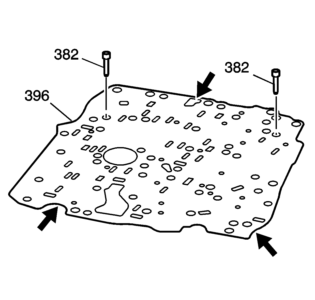
Note: The bonded spacer plate gasket assembly is not reusable and should be replaced any time it is removed from the transmission.
- Inspect the control valve body spacer plate and gasket assembly (396) for the following root cause:
| • | Damaged gasket sealing surfaces |
| • | Plugged or damaged screen/seal assemblies (382) |
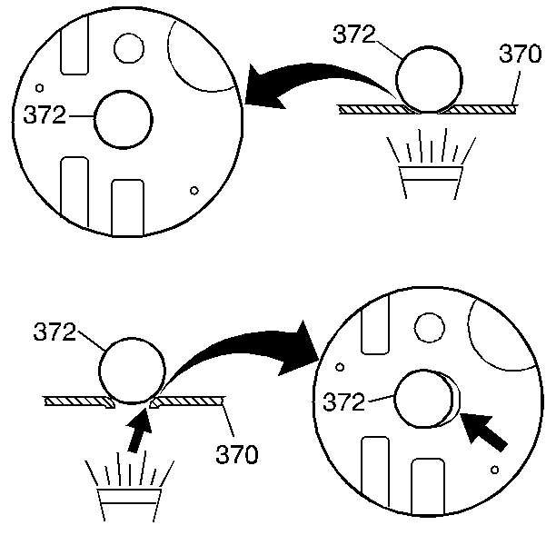
- Inspect each ball check valve seat (one at a time) on the spacer plate (370) for excessive peening.
| • | Place a ball check valve (372) on each seat |
| • | Use a flashlight to look for visible light between the ball check valve and the seat. |
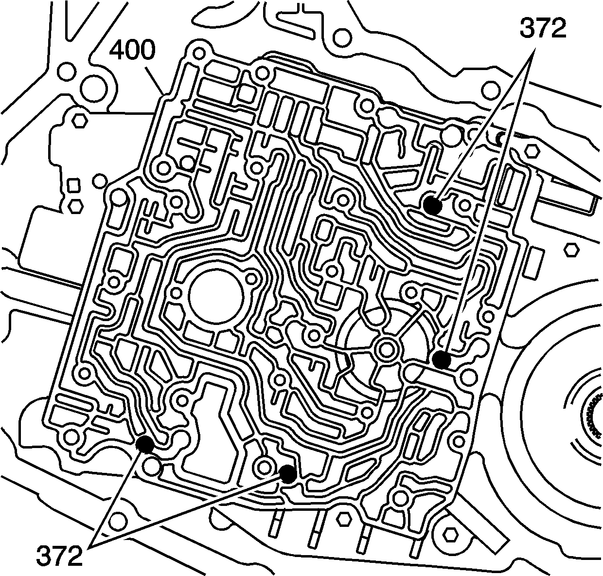
- Install 4 ball check valves (372) into the case cover (400), in the positions shown. Use
J-36850 lubricant
or equivalent in order to hold the ball check valves in the case cover (400).
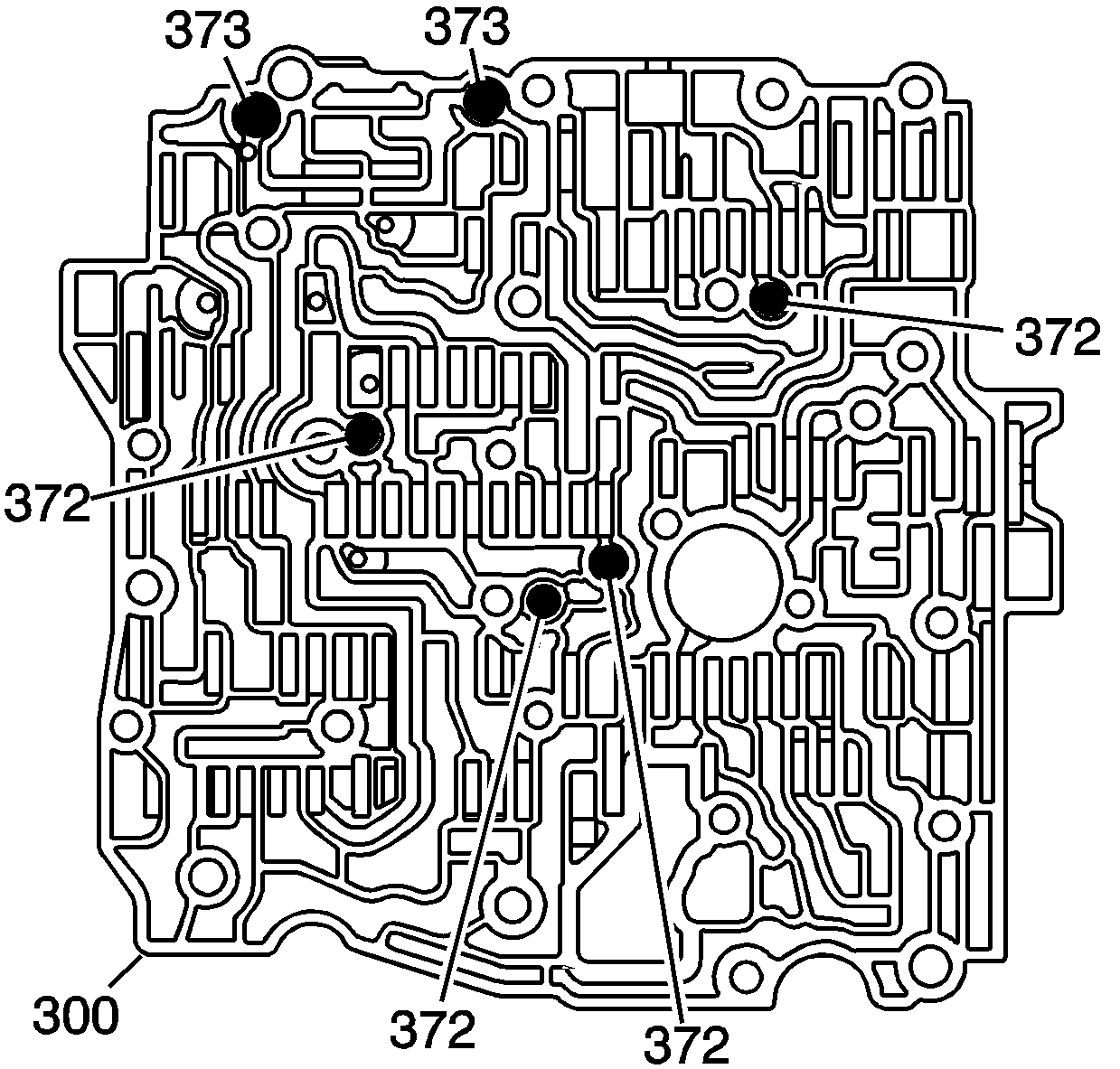
- Install the 2 larger ball check valves (373) and the 4 smaller ball check valves (372) into the control
valve body (300). Use
J-36850 lubricant
or equivalent in order to retain the ball check valves in the control valve body (300).
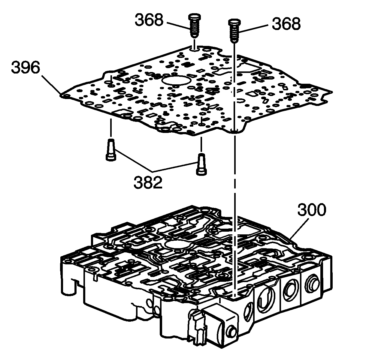
- Install the screen/seal assemblies (382) into the spacer plate and gasket assembly (396).
Note: The bonded spacer plate gasket assembly is not reusable and should be replaced any time it is removed from the transmission.
- Install the NEW spacer plate and gasket assembly (396) onto the control valve body (300).
- Install the bolts (368) to hold the spacer plate and gaskets onto the control valve body (300).
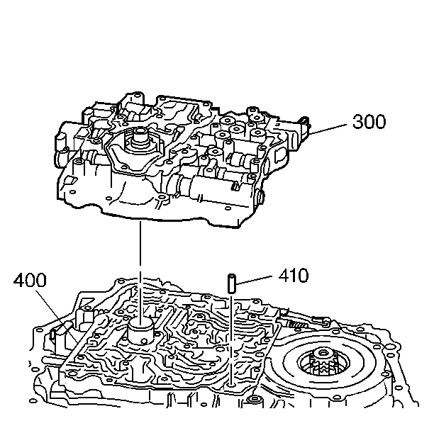
- Install the control valve body alignment sleeve (410) into the case cover (400).
Note:
| • | Use the control valve body alignment sleeve (410) and turbine shaft sleeve in the case cover (400) as guides. |
| • | Be sure that the ball check valves do not drop out of the control valve body (300) during assembly. |
- Install the control valve body (300) onto the case cover (400).
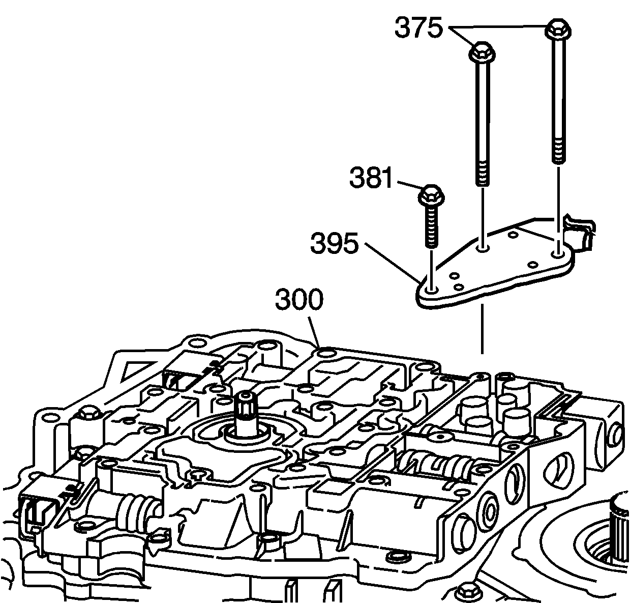
- Install the transmission fluid pressure (TFP) manual valve position switch
assembly (395) onto the control valve body (300).
Note: Finger start the bolts to prevent cross-threading.
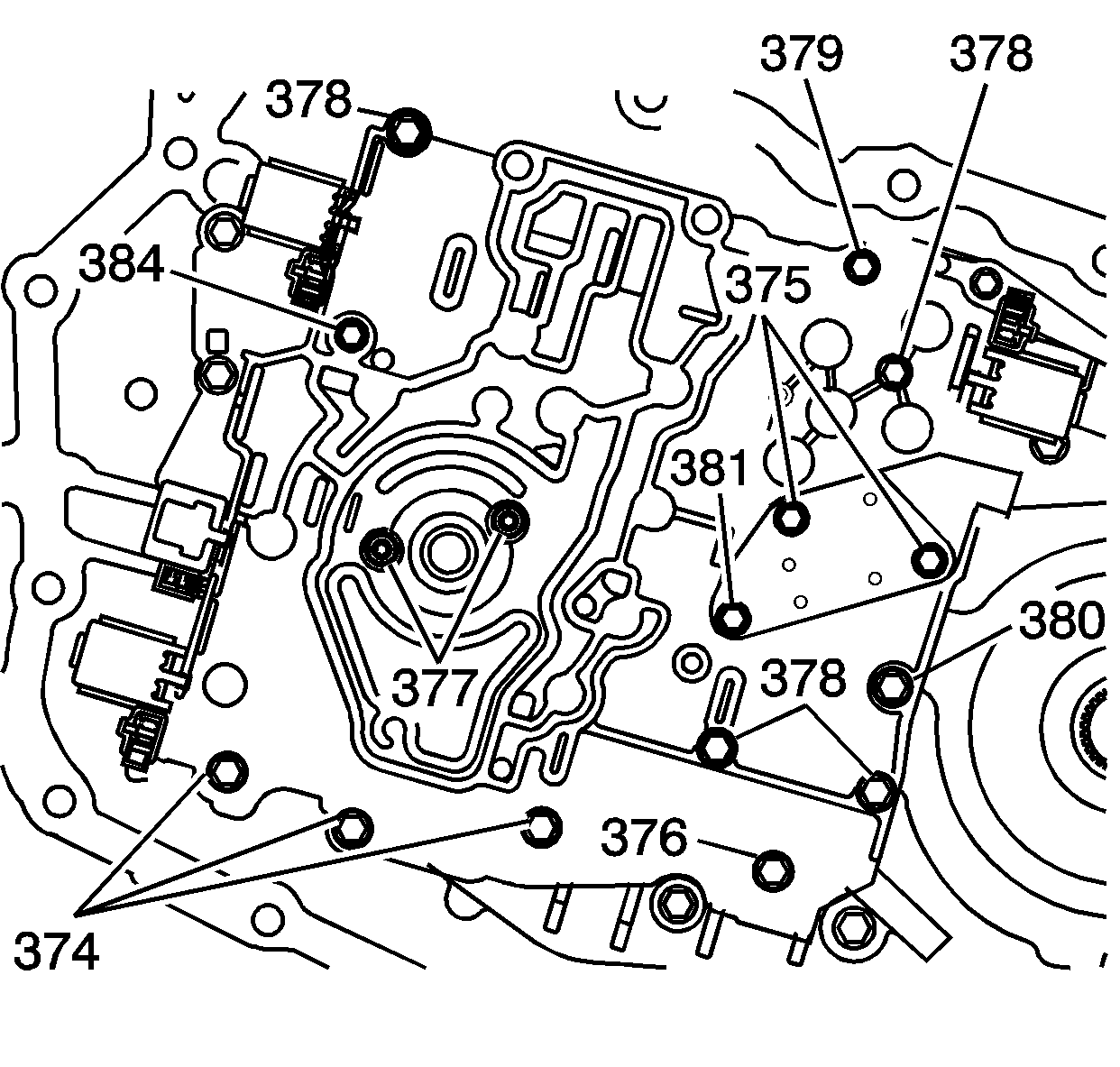
- Install the control valve body bolts (374-381, 384) as indicated.
Caution: Refer to Fastener Caution in the Preface section.
Note:
| • | Tighten the bolts in a spiral pattern starting with the bolts at the center of the control valve body. |
| • | If the bolts are tightened at random, valve bores may become distorted and inhibit proper valve operation. |
- Tighten the control valve body bolts (374-381, 384).
| • | 374 -
16 N·m (11 lb ft) |
| • | 375 -
12 N·m (106 lb in) |
| • | 376 -
12 N·m (106 lb in) |
| • | 377 -
12 N·m (106 lb in) |
| • | 378 -
12 N·m (106 lb in) |
| • | 379 -
16 N·m (11 lb ft) |
| • | 380 -
25 N·m (18 lb ft) |
| • | 384 -
12 N·m (106 lb in) |


