For 1990-2009 cars only
Removal Procedure
- Raise and support the vehicle. Refer to Lifting and Jacking the Vehicle.
- Remove the tire and wheel assembly. Refer to Tire and Wheel Removal and Installation.
- Lower the rear suspension support to gain clearance to the spindle rod to suspension support bolt. Refer to Support Replacement.
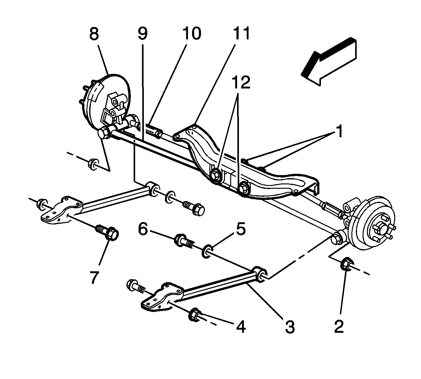
- Remove the bolt (1 or 2) and nut from the spindle rod and the rear suspension support.
- Remove the spindle rod to knuckle bolt and nut.
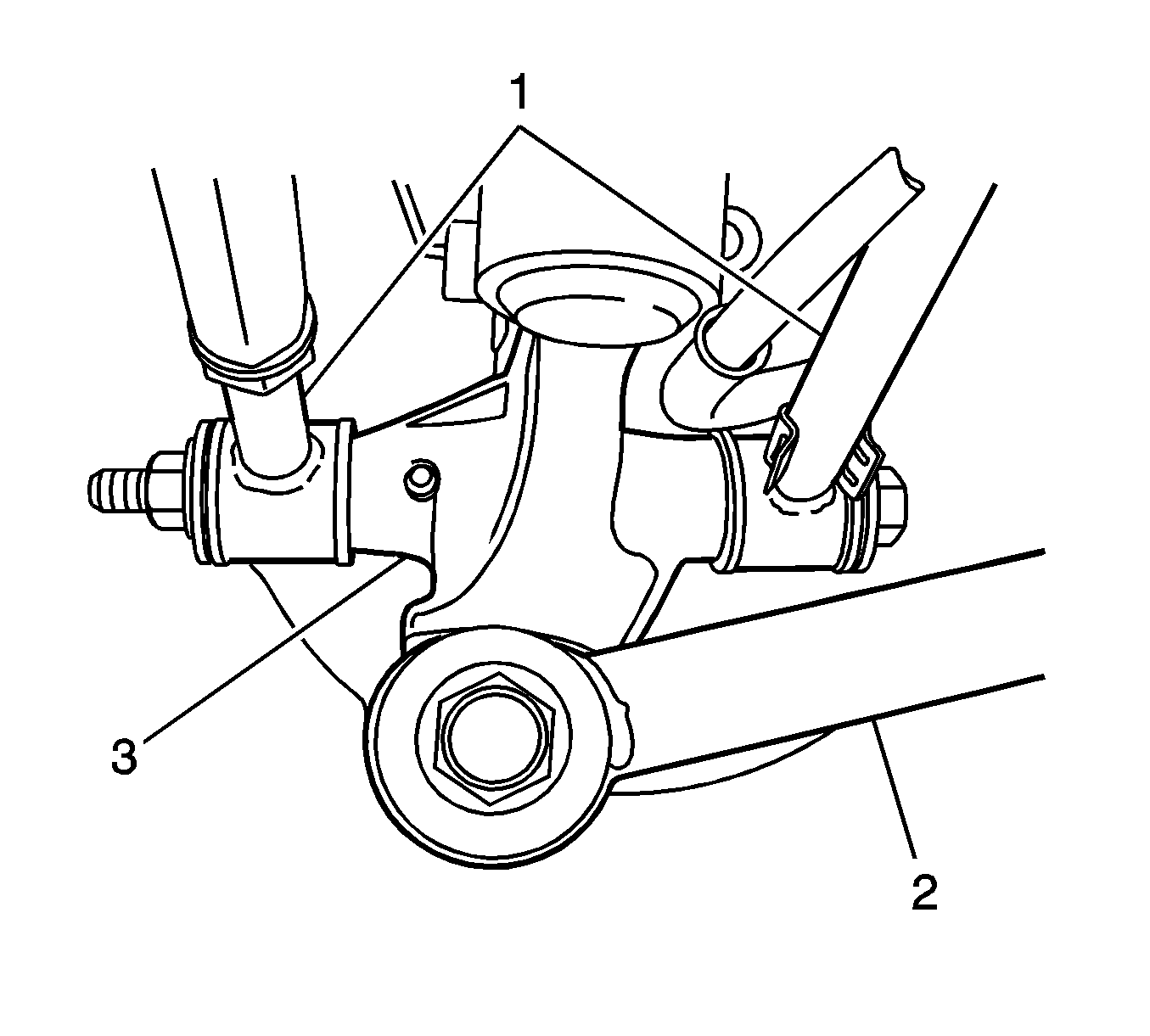
- Remove the spindle rod (1) from the vehicle.

Note: Use a transmission jack or suitable hoist stands to prop the rear suspension support.

Installation Procedure
- Install the spindle rod (1) to the vehicle.
- Install the spindle rod (1) to the knuckle (3).
- Install the spindle rod to knuckle bolt and nut. Do not tighten at this time.
- Install the spindle rod (9-10) to the rear suspension support.
- Install the bolt (1-2) and nut to the rear suspension support.
- Install the rear suspension support. Refer to Support Replacement.
- Install the tire and wheel assembly. Refer to Tire and Wheel Removal and Installation.
- Lower the vehicle.
- Adjust the wheel toe angle. Refer to Wheel Alignment Specifications.


Caution: Refer to Fastener Caution in the Preface section.
Tighten
Tighten the bolt to 135 N·m (100 lb ft).
Tighten
Tighten the bolt to 150 N·m (110 lb ft).
