For 1990-2009 cars only
Removal Procedure
Warning: Refer to Brake Dust Warning in the Preface section.
Warning: Refer to Brake Fluid Irritant Warning in the Preface section.
Caution: Refer to Brake Fluid Effects on Paint and Electrical Components Caution in the Preface section.
- Inspect the fluid level in the brake master cylinder reservoir.
- If the brake fluid level is midway between the maximum-full point and the minimum allowable level, then no brake fluid needs to be removed from the reservoir before proceeding. If the brake fluid level is higher than midway between the maximum-full point and the minimum allowable level, then remove brake fluid to the midway point before proceeding.
- Raise and suitably support the vehicle. Refer to Lifting and Jacking the Vehicle.
- Remove the rear tire and the wheel assembly. Refer to Tire and Wheel Removal and Installation.
- Hand tighten 2 wheel lug nuts to retain the rotor to the hub.
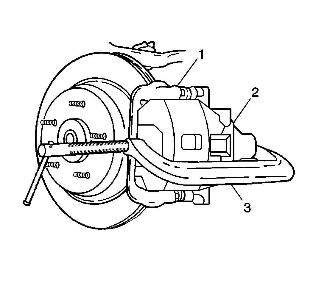
- Install a large C-clamp (3) over the top of the brake caliper (2) and against the back of the outboard brake pad.
- Tighten the C-clamp (3) until the caliper piston is pushed into the caliper bore enough to slide the caliper off the rotor.
- Remove the C-clamp (3) from the caliper.
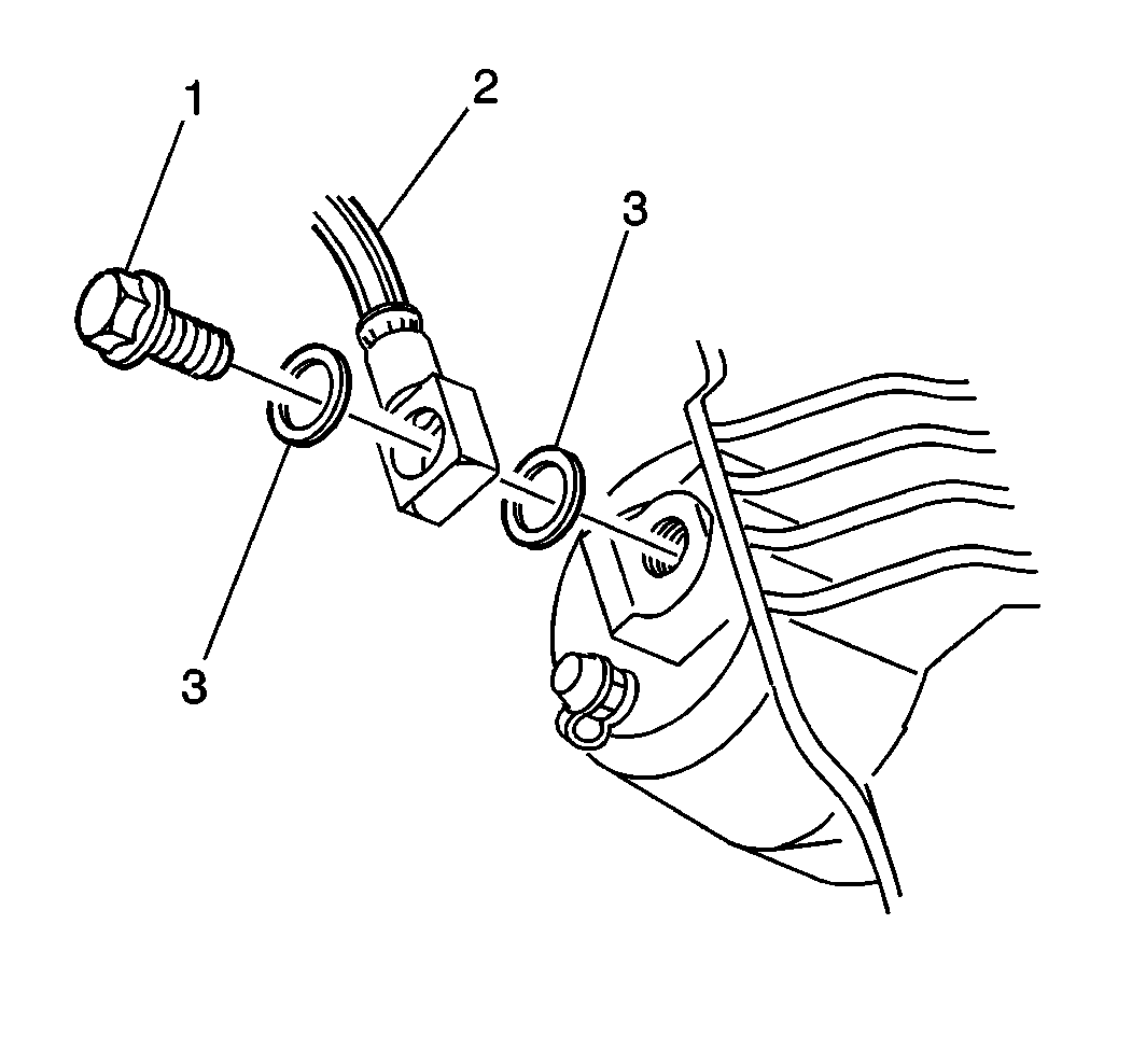
- Remove the brake hose-to-caliper bolt (1) from the caliper.
- Plug the opening in the rear brake hose (2) to prevent excessive brake fluid loss and contamination.
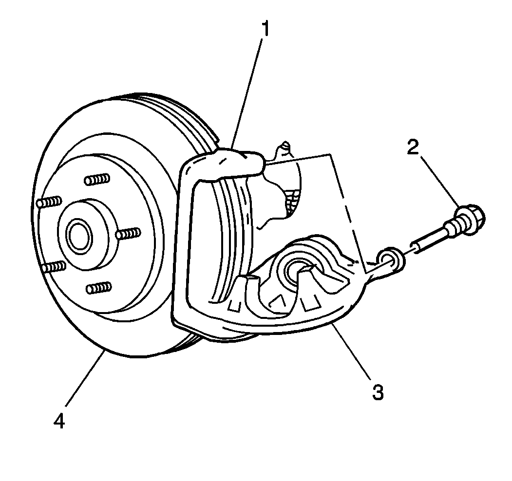
- Remove the 2 brake caliper guide pin bolts (2).
- Remove the caliper (3) from the rotor (4) and the caliper bracket (1).
- Inspect the caliper bracket bolt boots on the caliper bracket for the following conditions:
- Inspect the caliper bolts (2) for corrosion or damage. If corrosion is found, use new caliper bolts, including bushings, when installing caliper.


Discard the 2 copper brake hose gaskets (3). These gaskets may be stuck to the brake caliper and/or the brake hose end.

| • | Cuts |
| • | Tears |
| • | Deterioration |
| • | Replace any damaged caliper bracket bolt boots. Refer to Rear Disc Brake Hardware Replacement. |
Installation Procedure
- Install the caliper (3) over the rotor (4) and the caliper bracket (1). Ensure that the bushings are in place.
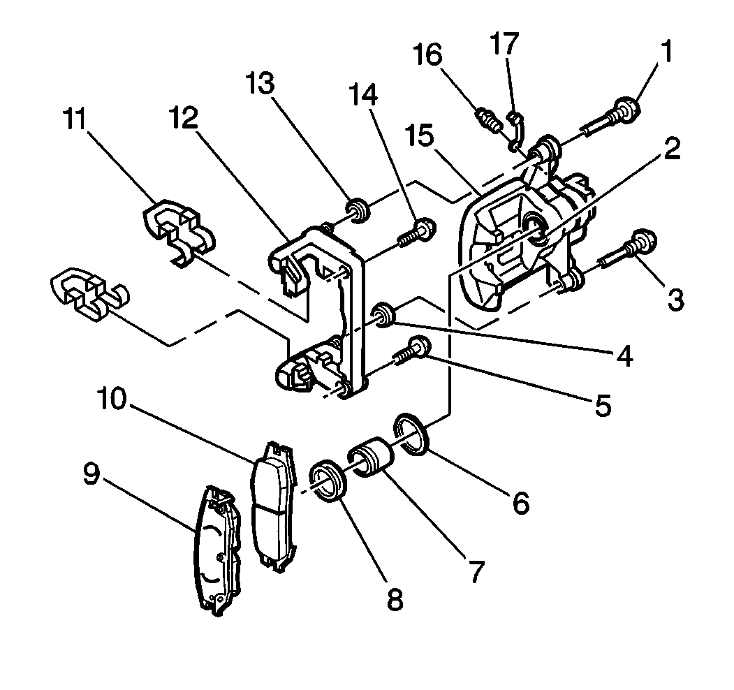
- Using high temperature, silicone brake lubricant lubricate the caliper guide pin bolts (1, 3). Do not lubricate the threads.
- Using high temperature, silicone brake lubricant lubricate the 2 bolt boots (4, 13) in the caliper bracket (12).
- Install the caliper guide pin bolts (1, 3) and tighten to 44 N·m (32 lb ft).
- Assemble the brake hose bolt (1) and the NEW copper brake hose gaskets (3) to the brake hose (2).
- Install the brake hose fitting bolt to the brake caliper and tighten to 54 N·m (40 lb ft).
- Bleed the brake system. Refer to Hydraulic Brake System Bleeding.
- Remove the 2 wheel lug nuts retaining the rotor to the hub.
- Install the rear tire and the wheel assembly. Refer to Tire and Wheel Removal and Installation.
- Fill the master cylinder to the proper level with clean brake fluid. Refer to Master Cylinder Reservoir Filling.


Caution: Refer to Fastener Caution in the Preface section.
Note: Ensure the bolt boots fit securely in the groove of the caliper bolts. Do not to pinch or tear the boots. If the boots are damaged, they must be replaced.
Note: Install new brake hose fitting gaskets.

