DRIVEABILITY CORRECTIONS/3.0L CODE E -NEW COMPONENT LISTING

MODELS AFFECTED: ALL FEDERAL AND CALIFORNIA 1983 CENTURYS BEGINNING WITH VIN D6 415302 and DD 444821
Several calibration and component changes have been released for production These new component parts are not to be used on vehicles with VIN's prior to the above break points.
Couponent changes: - Electric EFE - 19 cu.in. Air Pump - ECM - PRCM - Final Drive Ratios - Two (2) Speed 150 Watt Cooling Fan - Carburetor Assembly - EGR Solenoid and EGR Valve Asm. - Air Conditioning Cutouts
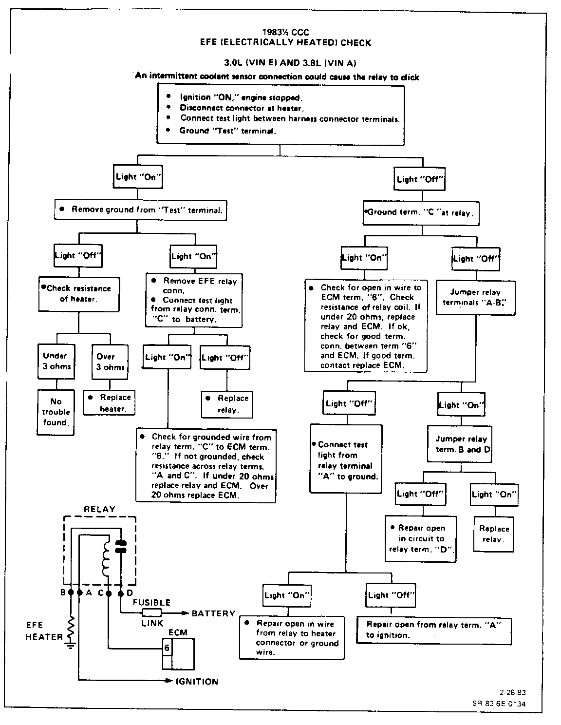
Electric EFE - Early Fuel Evaporation
An electric EFE grid located under the carburetor base plate is controlled by the ECM to turn off when 90 DEG C engine coolant temperature is reached. The new electric EFE replaces the vacuum operated exhaust heat riser EFE used on vehicles prior to the VIN breakpoints. This new EFE eliminates driveability conditions during warm up operation.
A.I.R. - Air Injector Reactor Pump
The new A.I.R. system has nearly the same air output as the system used on prior breakpoint vehicles; however, the A.I.R. pump capacity and pulley sizes (6-3/8" diamter) were changed to effectively reduce the A.I.R. pump drive speed resulting in quieter pump operation.
ECM - Electronic Control Module
The new ECM is a single board unit, part #1226153. Some data stream changes were required. Usage of the ALCL scan tools has changed as follows:
Mixture control solenoid duty cycle. Dwell readings of 0 DEG at idle and 60 DEG at part throttle will be seen on some ALCL tools indicating the scan tool is unusable. If these readings are obtained, a standard external dwell meter will be required to obtain the correct dwell readings.
Oxygen sensor voltages when using ALCL scan tool as high as 1.4 volts will be seen when a full rich exhaust condition exists. Previously 1.0 volt maximum read out was seen.
PROM
New PROM's have also been released for 19831/2. Part numbers are:
3.0L Federal Century THM 125C - 1226556 3.0L California Century TR4 125C - 1226557
Program changes in the PROM have revised calibration for torque convertor clutch (TCC) and changed idle quality with new idle speed control logics at idle. It also incorporates a higher base idle speed of 640 RPM, along with a driveability feature, which functions to hold the idle speed higher for a short time.
Air Conditioning System Operation
The PROM turns the air conditioning off when vacuum falls below 6 inches (approximtely 80 kPa manifold absolute pressure) for five seconds maximum. If the vacuum exceeds 9 inches (approximately 70 kPa manifold absolute pressure) the air conditioning is turned on and the timer reset. The air conditioner cutout function was designed to improve acceleration performance.
When operating the air conditioning and turning the steering to the full right or left lock position, a pressure switch in the power steering line turns off the air conditioning compressor.
Final Drive Ratio
Axle ratios have been changed from 2.53 to 1 to 2.97 to 1 for improvement acceleration and performance.
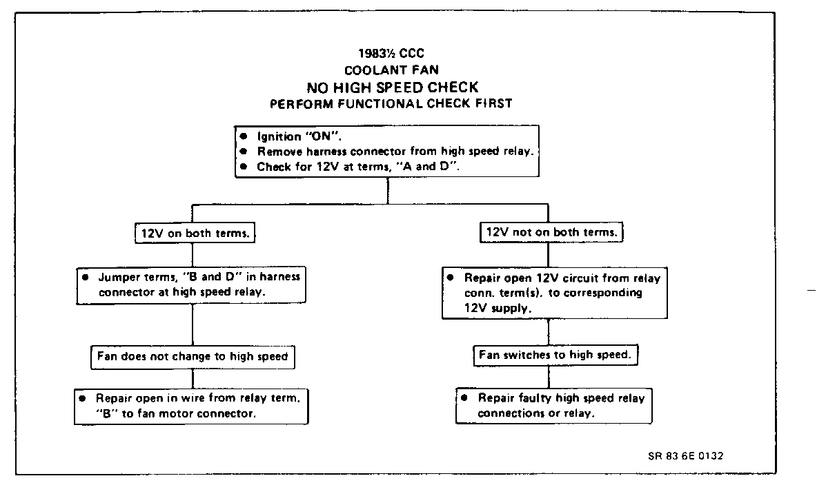
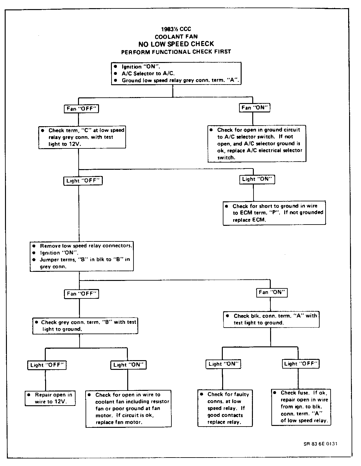
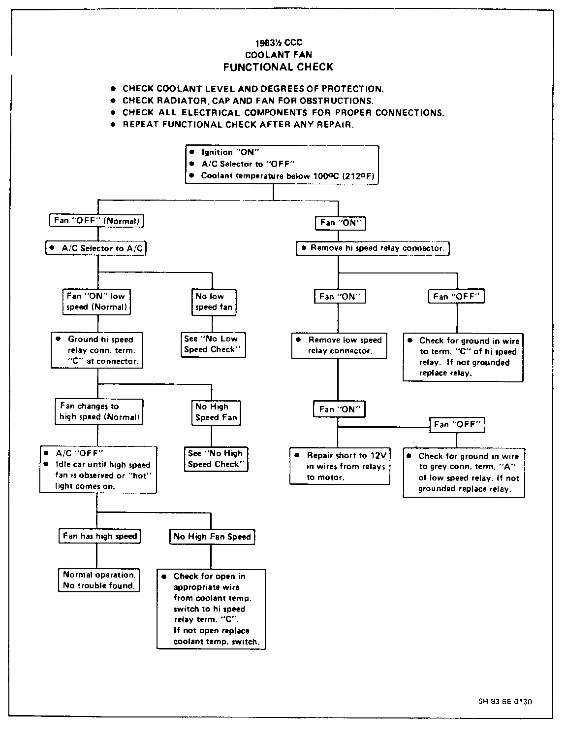
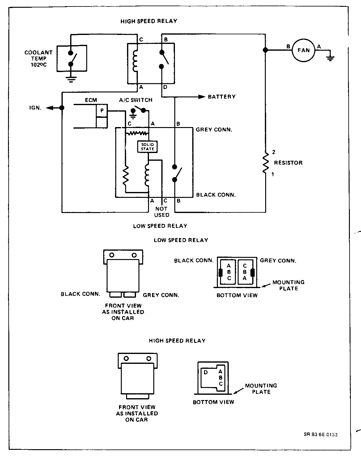
Two (2) Speed Cooling Fan
This change results in quieter fan operation at low speed and increased cooling at high speeds. Fan speeds are controlled by the ECM VIA inputs from temperature sensor, A/C switch, vehicle speed sensor.
EGR Solenoid and EGR Valve Asm.
EGR solenoid and EGR valve assembly have been changed. EGR solenoid assembly controls only the EGR valve. The previous models controlled EGR and EFE.
Carburetor Specifications Lean M/C Idle Carburetor Float Stop Paddle Mixture Number Setting Screw Travel Needle
17083194 10/32 " 1-30 Gage 4/32 *2 17084193 *3 17084195
Idle Choke Choke Vac Vac Choke Air Stat Link Break Break and Bleed Lever Cam Front Rear Loader
1.756 Gage .120 Gage 17 DEG 27 DEG 25 DEG 35 DEG *1
*1. Preset 1.756G, final adjustment on vehicle *2. Preset 3 turns, final adjustment on vehicle *3. Gaging Tool J-33815-1 (Brass Bullet)
Fast Idle Specifications
1. Set choke fast idle cam on high step
2. Start engine set fast idle with fast idle adjustment screw to 2400 RPM
Field Service Resetting Specification for Idle Speed Control
ISC Minimum Idle Procedure
1. Block Drive Wheels 2. Cooling Fan Off 3. Engine in Closed Loop 4. Retract ISC Motor 5. Set Base Idle to 500 RPM in Drive
ISC Maximum Idle Procedure
1. Block Drive Wheels 2. Cooling Fan Off 3. Engine in Closed Loop 4. Fully Extend ISC Motor 5. Set Maximum Idle by Adjusting ISC to 1350 RPM in Drive
Throttle Position Sensor Specifications
1. Retract ISC to Minimum Idle 2. Set T.P.S. Voltage to .57 +/- .01 Volts
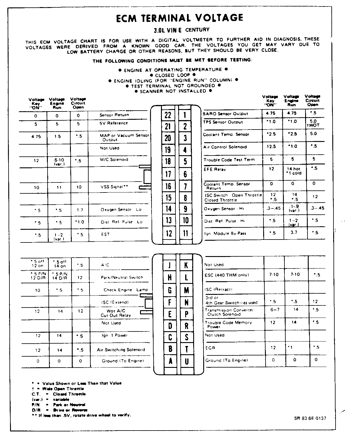
Included in this bulletin are updated diagnostic charts for these changes.
General Motors bulletins are intended for use by professional technicians, not a "do-it-yourselfer". They are written to inform those technicians of conditions that may occur on some vehicles, or to provide information that could assist in the proper service of a vehicle. Properly trained technicians have the equipment, tools, safety instructions and know-how to do a job properly and safely. If a condition is described, do not assume that the bulletin applies to your vehicle, or that your vehicle will have that condition. See a General Motors dealer servicing your brand of General Motors vehicle for information on whether your vehicle may benefit from the information.
