ELECTRICAL DIAGNOSIS EFE. INFORMATION UPDATE

MODELS AFFECTED: 19831/2 CENTURYS WITH EFE EQUIPPED 3.0L V6 ENGINES (VIN CODE E)
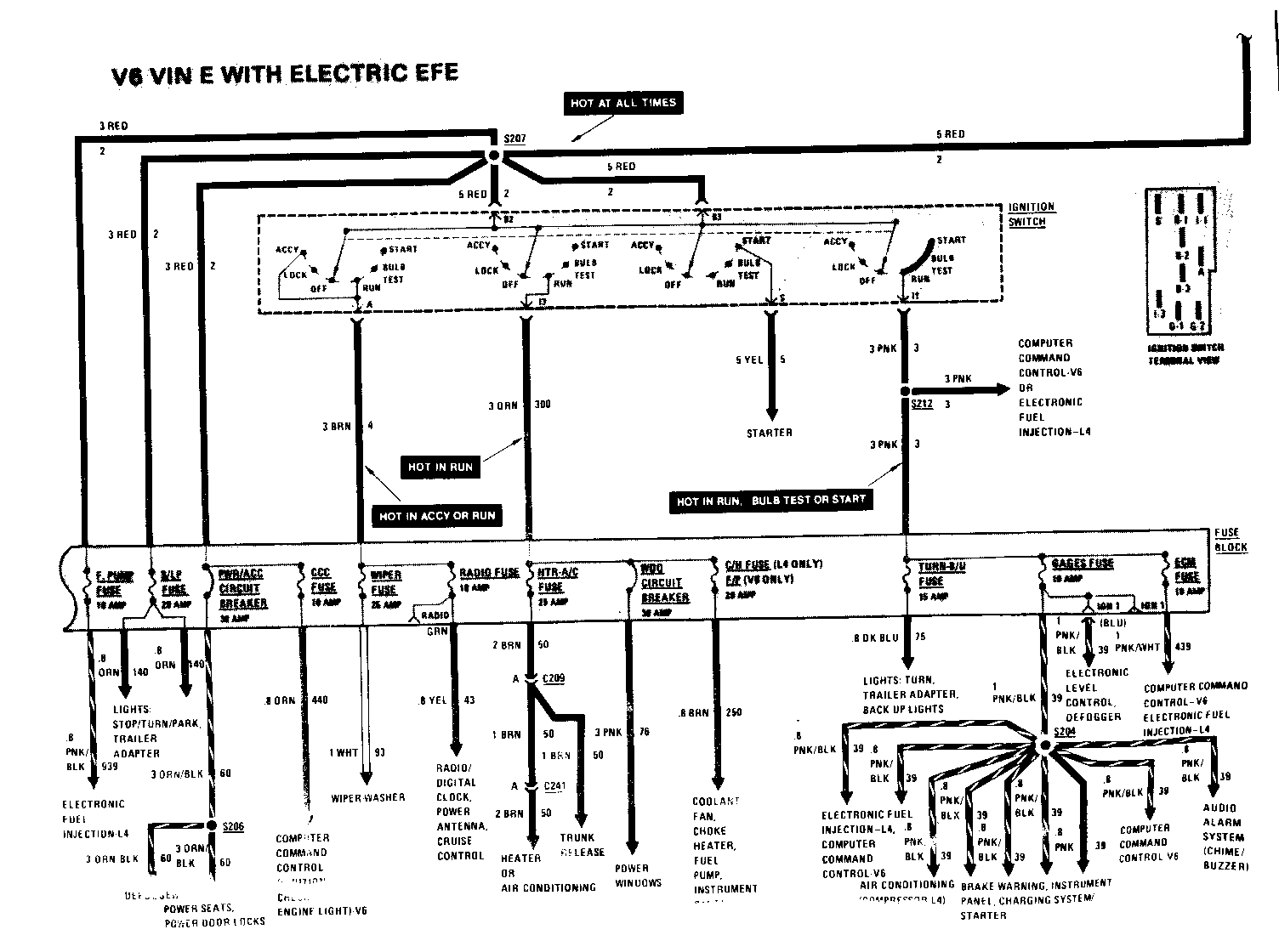
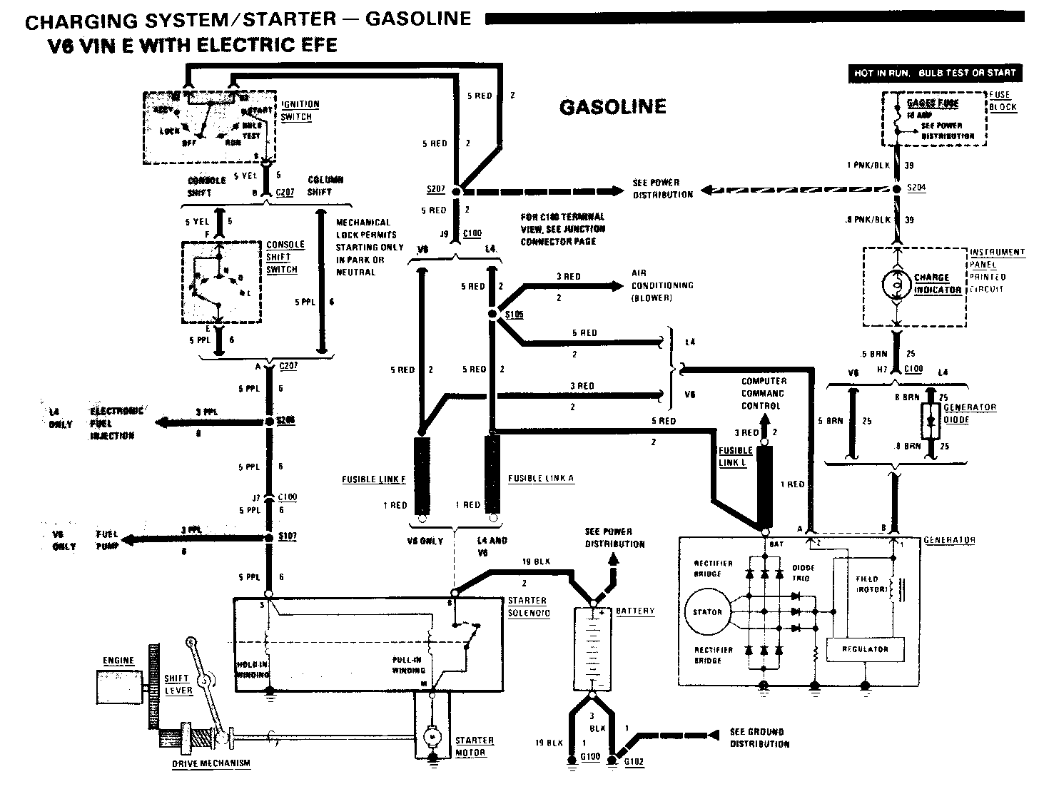
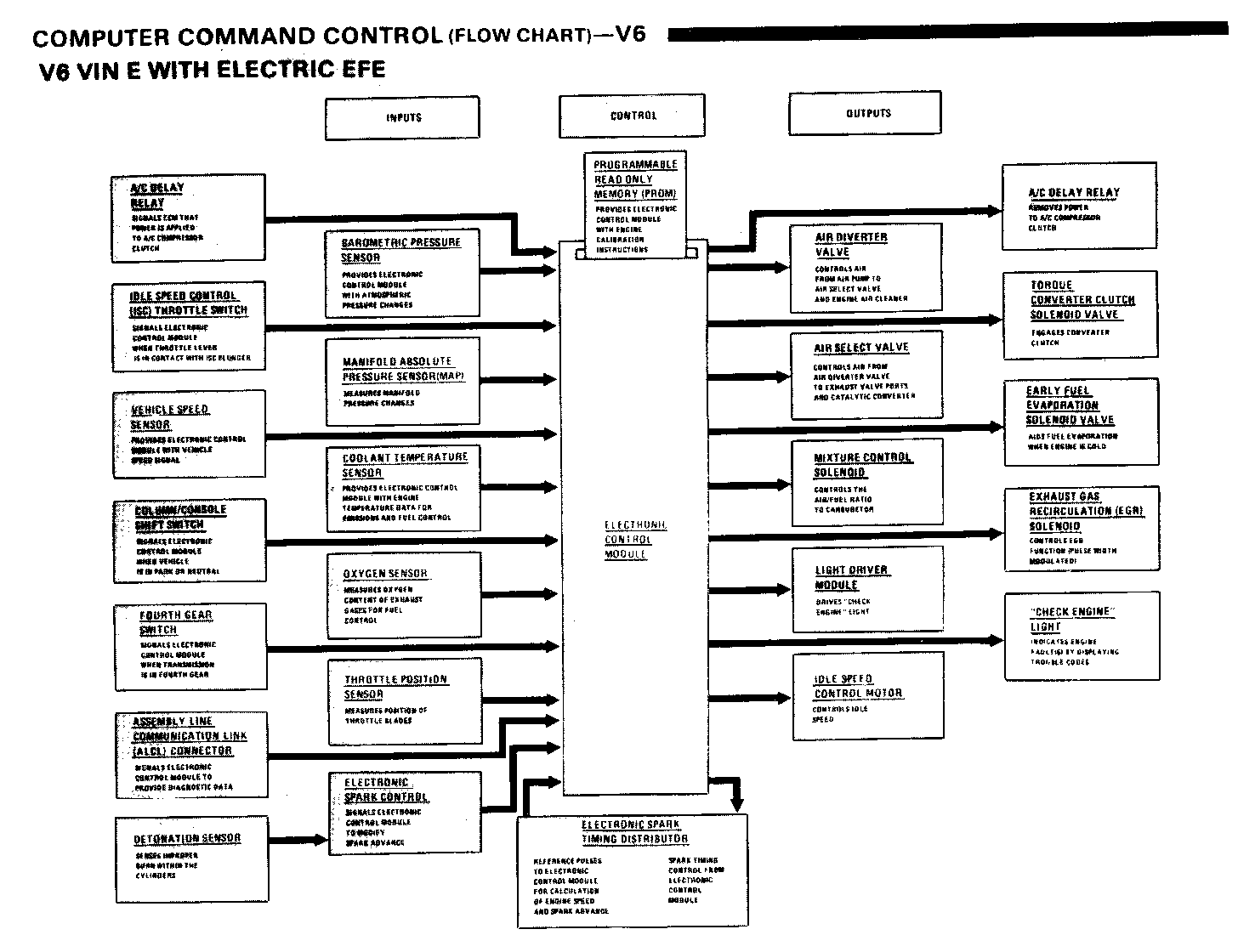
Included with this bulletin are the electrical schematics and electrical diagnosis information for the 19831/2 Centurys with EFE equipped 3.0L V6 engines. This information should be kept with your 1983 service manual until the next revision is issued.
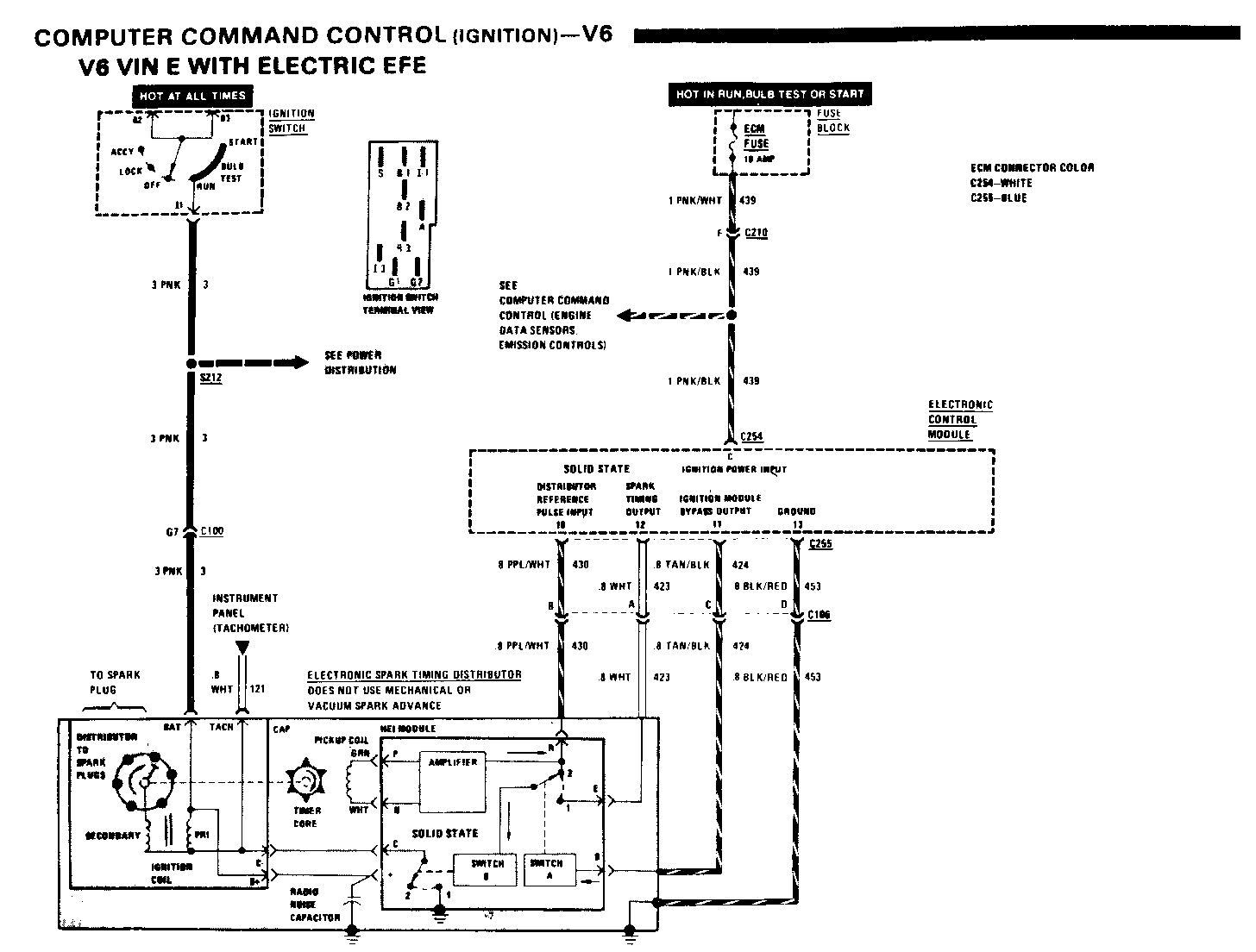
COMPUTER COMMAND CONTROL (IGNITION)-V6 SEE SECTION 6E FOR DETAILED DIAGNOSTIC PROCEDURES
COMPONENT LOCATION Page-Figure
Electronic Control Module... Behind RH side of I/P....................136-1 Fuse Block.................. Behind RH side of I/P....................102-1 Ignition Switch ............ Behind I/P, top of steering column.......179-2 C100 (34 cavities).......... LH cowl, behind shock tower..............167-1 C106 (4 cavities)........... RH side of engine, left of distributor...237-1 C210 (15 cavities).......... Behind glove box, below support bracket..136-1 S117........................ CCC harness, below distributor...........231-2 S212.........................I/P harness, above steering column.......183-1
CIRCUIT OPERATION
Ignition
The ELECTRONIC SPARK TIMING (EST) DISTRIBUTOR contains the ignition coil, amplifier, timer core, electronic switches, and magnetic pickup coil. Voltage is available to the EST DISTRIBUTOR when the IGNITION SWITCH is in "Run," "Bulb Test," or "Start." PICKUP ASSEMBLY
As the timer core turns, a magnetic circuit closes before each time a spark plug is to fire. The magnetic circuit is like an electric circuit with the magnet acting as battery and the pole pieces and shaft acting as wires. The pointed teeth on the pole piece and timer core act as a switch. When the teeth separate, the magnetic circuit opens. When the teeth come together, the switch closes and a magnetic pulse flows through the pickup. As the timer core turns, the magnetic circuit is rapidly closed and opened. Each rapid magnetic pulse produces a low voltage pulge which is applied to the amplifier. The amplifier increases the pulse voltage and sends reference pulses to terminal 10 of the ELECTRONIC CONTROL MODULE (ECM).
The ECM receives and processes these pulses. Based on the rate of these input reference pulses and the data it receives from engine sensors, the ECM selects the spark timing (retard or advance) needed for best engine performance. Then the ECM sends a control signal from terminal 11 to electronic switch A in the EST DISTRIBUTOR. This signals the switch to move to position 1 which allows the EST output timing pulse from terminal 12 of the ECM to be applied to electronic switch B.
When electronic switch B closes, it connects the ignition coil primary (PRI) to ground.
Current flows through the coil and builds up a magnetic field around the coil. When the switch opens, the magnetic field at the ignition coil primary (PRI) quickly falls. The quick fall of the magnetic field produces a high voltage in the ignition coil secondary (SEC). The high voltage passes to the rotor and cap and then to a spark plug to fire the mixture in the proper cylinder.
BY-PASS MODE
Under certain conditions, for example during start or with a problem in the EST circuit, the ECM will provide fixed timing. In such cases, the control signal sent from terminal 11 of the ECM will tell electronic switch A contacts to remain in position 2. This is called the by-pass mode because the spark control circuitry of the ECM does not modify engine timing. Instead, the spark control voltage goes directly from the amplifier, through switch A to electronic switch B.
The ECM can also be operated in the bypass mode by disconnecting the ELEC- TRONIC SPARK TIMING pigtail connector, C106. This disconnects the control signal from the ECM.
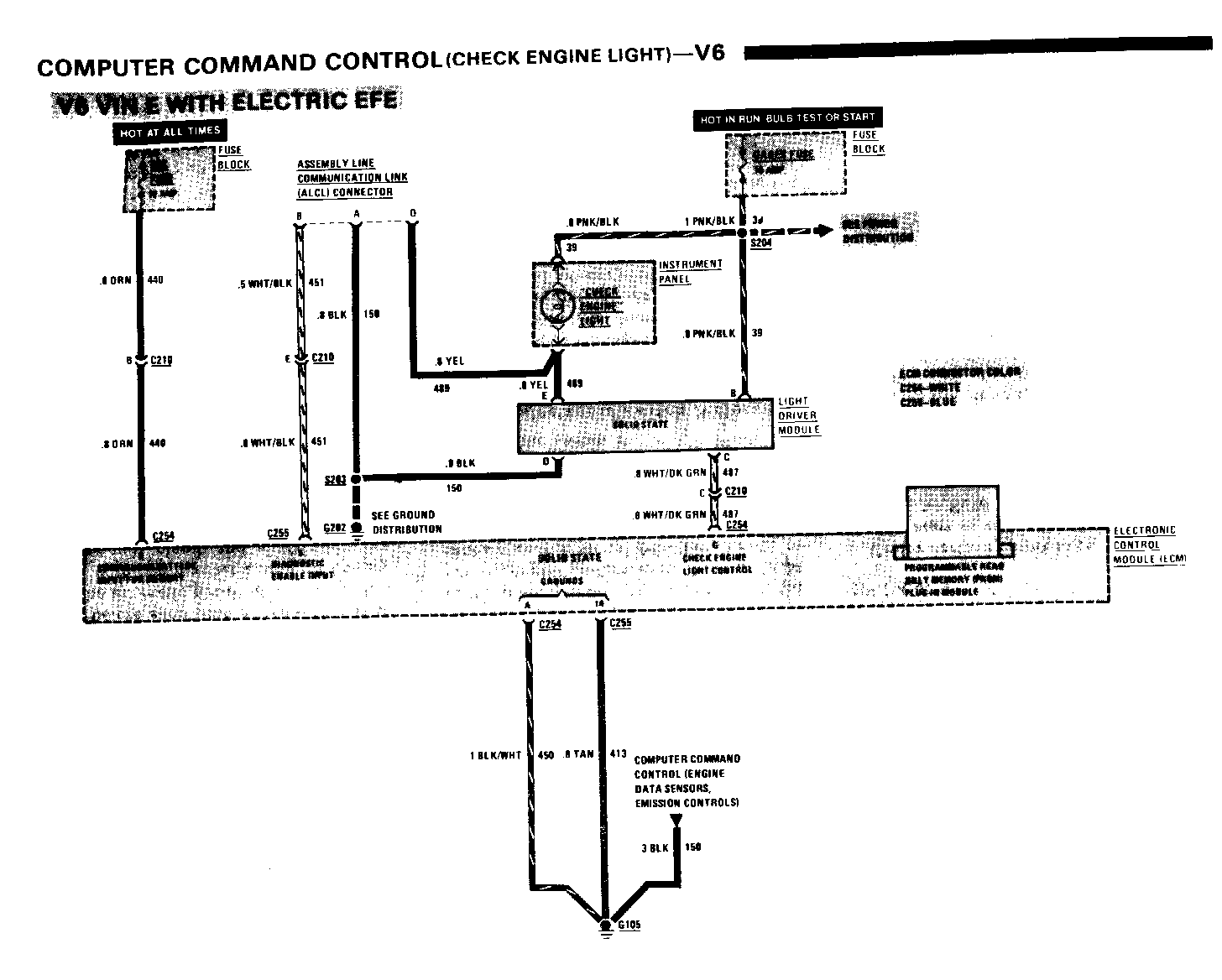
COMPUTER COMMAND CONTROL (CHECK ENGINE LIGHT)-V6 SEE SECTION 6E FOR DETAILED DIAGNOSTIC PROCEDURES
COMPONENT LOCATION Page-Figure
Assembly Line Communication Link (ALCL) Connector........ On bottom of I/P, near steering column...113-1 Electronic Control Module..... Behind RH side of I/P....................136-1 Fuse Block.................... Behind RH side of I/P....................102-1 Light Driver Module........... Taped to I/P hamess, behind glove box....183-1 C210 (15 cavities).............Behind glove box, below support bracket..136-1 G105.......................... Top of engine, left of generator.........237-1 G202.......................... Behind I/P, right of ash tray............183-1 S203.......................... I/P harness, right of steering column....183-1 S204.......................... I/P harness, near ash tray...............183-1
CIRCUIT OPERATION
The ELECTRONIC CONTROL MODULE (ECM) detects the most common problems in the COMPUTER COMMAND CONTROL SYSTEM (the sytem). It warns the driver of a problem by turning on the "CHECK ENGINE" LIGHT while the engine is running. The LIGHT DRIVER MODULE is controlled by the ECM to turn on the "CHECK ENGINE" LIGHT. The light also goes on for 1 to 4 seconds when the engine is started and then goes out. This is a bulb test.
The ECM records problems in its memory, and when the self-diagnostic system is activated, it flashes a trouble code through the "CHECK ENGINE" LIGHT. Because ECM does not self-diagnose all problems, the absence of a code does not necessarily mean that the system is operating properly. When the self- diagnostic features of the ECM indicates no problem, but the Command Control System is "suspect," a System Performance check is necessary. (See Section 6E.)
HOW TO GET CODES
1. With the engine NOT running and the IGNITION SWITCH in "Run," grounding "TEST" terminal B of the ASSEMBLY LINE COMMUNICATION LINK (ALCL) CONNECTOR (jumpering between terminals A and B) will cause the following:
The "CHECK ENGINE" LIGHT will flash code 12-one short and two long flashes. This shows that the ECM self-diagnostic system is working. Then if any Trouble Codes are stored, they will also be flashed.
The ECM will send a 30 DEG dwell signal to the FUEL METERING SOLENOID.
The ECM will turn on all ECM controlled solenoids.
The ECM will not record additional Trouble Codes when components are disconnected for troubleshooting. Remember to unground the "TEST" terminal before starting the engine.
2. With the engine running, grounding "TEST" terminal B of the ASSEMBLY LINE COMMUNICATION LINK (ALCL) CONNECTOR (jumpering between terminals A and B) will cause the "CHECK ENGINE" LIGHT to flash the Trouble Code three times. If more than one problem exists, the lower number code flashes first followed by the higher number codes. Each will flash three times. The codes will continue to flash in numerical order as long as the "TEST" terminal B is ground.
The ECM will not record additional Trouble Codes when components are disconnected for troubleshooting.
After repairs have been made, the ECM memory is cleared by removing the voltage supply to the ECM. This is done by removing the CCC FUSE for 10 seconds. Remember to unground the "TEST" terminal before starting the engine.
The PROGRAMMABLE READ ONLY MEMORY (PROM) is the set of calibration instructions for the ECM. Each vehicle type has a specific PROM designed for its use. Should PROM replacement be necessary, care must be taken not to interchange or incorrectly install PROMS.
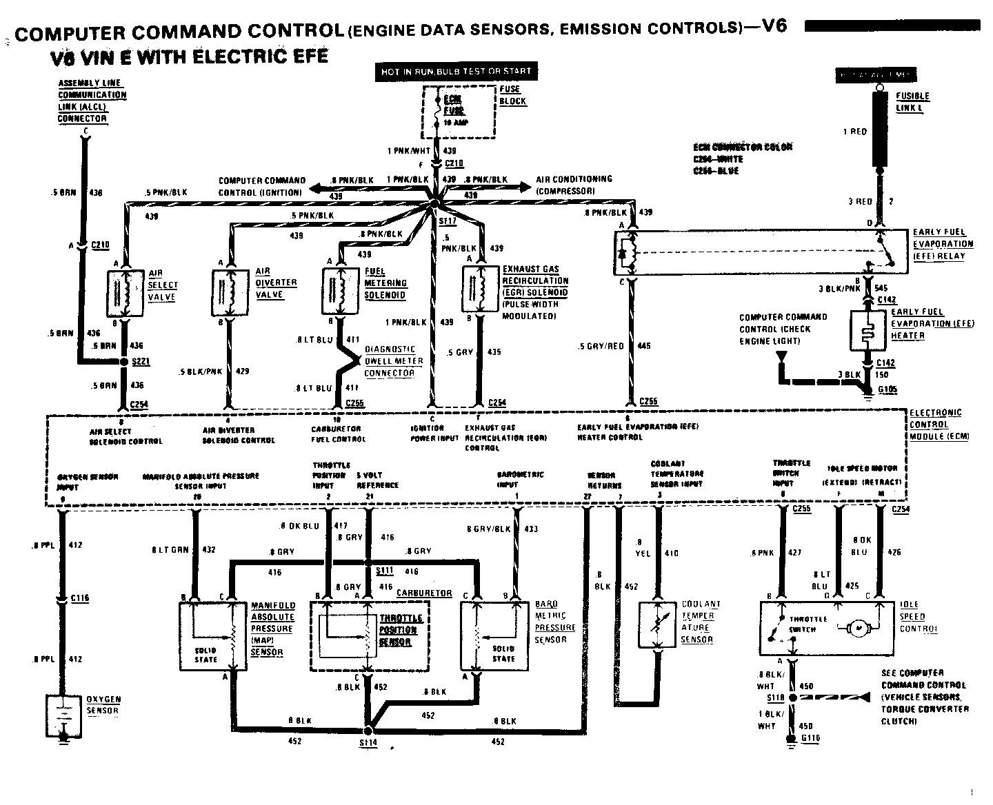
COMPUTER COMMAND CONTROL (ENGINE DATA SENSORS, EMISSION CONTROLS)-V6 SEE SECTION 6E FOR DETAILED DIAGNOSTIC PROCEDURES
COMPONENT LOCATION Page-Figure
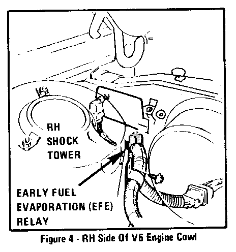
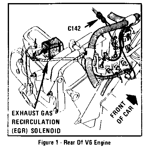
AIR Diverter Valve.......... On RH side of LH front wheel well..........236-1 AIR Select Valve.............On RH side of LH front wheel well..........236-1 Assembly Line Communication Link (ALCL) Connector.......On bottom of I/P, near steering column.....113-1 Barometric Pressure Sensor...Taped to CCC hamess, behind glove box......136-1 Coolant Temperature Sensor...Top of engine, left of distributor.........237-1 Diagnostic Dwell Meter Connector...................Taped to CCC harness, ahead of carburetor..237-2 Early Fuel Evaporation (EFE) Heater................Under base of carburetor Early Fuel Evaporation (EFE) Relay.................Upper RH side of engine cowl...............303-4 Electronic Control Module....Behind RH side of I/P......................136-1 Exhaust Gas Recirculation (EGR Solenoid)..............Center of rear valve cover.................314-1 Fuel Metering Solenoid.......Top of engine, ahead of carburetor........ 237-1 Fuse Block...................Behind RH side of I/P..................... 102-1 Fusible Link L...............Front of engine, near starter motor........212-3 Idle Speed Control...........Ahead of LH side of carburetor............ 237-2 Manifold Absolute Pressure (MAP) Sensor................On air filter assembly.................... 237-3 Oxygen Sensor................On rear exhaust manifold.................. 237-1 C116 (1 cavity)..............Rear of engine, near center of valve cover.237-1 C142 (2 cavities)............Top of engine, left of distributor........ 314-1 C210 (15 cavities)...........Behind glove box, below support bracket....136-1 G105.........................Top of engine, left of generator.......... 237-1 G110.........................Top of engine, left of generator.......... 237-1 S111.........................CCC harness, left of distributor.......... 237-1 S114.........................CCC harness, left of generator............ 237-1 S117.........................CCC harness, below distributor........... 231-2 S118.........................CCC harness, left of distributor.......... 237-1 S221.........................CCC harness, behind I/P near grommet.......136-1
CIRCUIT OPERATION
Engine Data Sensors
The COOLANT TEMPERATURE SENSOR measures engine coolant temperature and sends a signal to the ECM.
The MANIFOLD ABSOLUTE PRESSURE (MAP) SENSOR detects changes in manifold pressure. Such changes indicate the need for an adjustment in air/fuel mixture and electronic spark timing to maintain efficient engine operation.
The OXYGEN SENSOR measures the oxygen content of the exhaust gases and compares it with the oxygen content of the outside air. The difference between the two measurements creates a small voltage that is fed to the ECM. This voltage determines the air/fuel mixture. With a high OXYGEN SENSOR input voltage, the ECM will tell the FUEL METERING SOLENOID to lean the mixture. (Reduce the fuel in the air/fuel mixture.) With a low OXYGEN SENSOR input voltage, the ECM will tell the FUEL METERING SOLENOID to enrich the mixture. (Increase the fuel in the air/fuel mixture.)
NOTICE: Do not measure OXYGEN SENSOR output voltage. The current drain of most meters can permanently damage the OXYGEN SENSOR.
The THROTTLE POSITION SENSOR monitors the position of the throttle.
The BAROMETRIC PRESSURE SENSOR provides information to the ECM on atmospheric pressure changes. The ECM adjusts the air/fuel mixture in response to this information.
COMPUTER COMMAND CONTROL (ENGINE DATA SENSORS, EMISSION CONTROLS-V6) SEE SECTION 6E FOR DETAILED DIAGNOSTIC PROCEDURES
Emission Controls
The AIR SELECT VALVE directs air to the exhaust valve ports or to the midbed of the catalytic converter depending on car operating conditions. When the engine is cold, the ECM grounds the AIR SELECT VALVE solenoid. The valve switches, directing air to the cylinder exhaust ports. When the engine is warm or when the system is in closed loop mode, the ECM removes ground from the AIR SELECT VALVE solenoid. The AIR SELECT VALVE switches back to its de-energized position and air is directed to the midbed of the catalytic converter.
The AIR DIVERTER VALVE directs air to the AIR SELECT VALVE or to the air cleaner, depending on operating conditions. In most driving modes the ECM will ground the AIR DIVERTER VALVE solenoid.
* The EXHAUST GAS RECIRCULATION (EGR) SOLENOID controls vacuum to the EGR valve. The EGR SOLENOID is controlled by a variable duty cycle signal from the ECM. When the engine is warm, a 0% duty cycle signal is provided and the EGR valve is full on. When the engine is cold, a 100% duty cycle signal is provided and the EGR valve is full off. The EGR valve can be varied between full off and full on.
Fuel Control
The FUEL METERING SOLENOID changes the air/fuel ratio by allowing more or less fuel to mix with the air in the carburetor. With the solenoid off, maximum fuel flows to the idle and main metering jets.
When the solenoid is operated, it cycles on and off 10 times per second in response to ECM pulses. Leaning of the air/fuel mixture (reducing the amount of fuel mixed with air) is controlled by varying the "on" time of each pulse. The longer the "on" time the leaner the mixture. The relationship between the "on" time and the "off" time can be measured with a dwell meter at the DIAGNOSTIC DWELL METER CONNECTOR.
Early Fuel Evaporation (EFE) System
The EARLY FUEL EVAPORATION (EFE) SYSTEM provides quick fuel evaporation which aids cold engine operation. Exhaust emissions are also reduced.
When the ECM senses cold engine operation, it grounds the coil of the EFE RELAY. Current flows through FUSIBLE LINK L, the closed contacts of the EFE RELAY and the EFE HEATER to ground. The heater directly warms the air/fuel mixture entering the intake manifold.
Idle Speed Control
The IDLE SPEED CONTROL (ISC) system allows the engine to maintain proper idle speeds under various load conditions. The ECM monitors the IDLE SPEED CONTROL THROTTLE SWITCH. The opening or closing of this switch tells the ECM when the driver is depressing the accelerator. When the accelerator is released, the ECM selects the idle speed and "commands" the idle speed motor to extend or retract. This varies the engine RPM as required.
When the driver depresses the accelerator, the throttle stop moves away from the ISC, closing its throttle switch. The ISC is then commanded to extend, awaiting the release of the acceleratoi. When the driver releases the accelerator, the throttle stop again touches the ISC and opens its throttle switch. The ISC is then commanded to retract at a set speed, providing a gradual throttle closing.
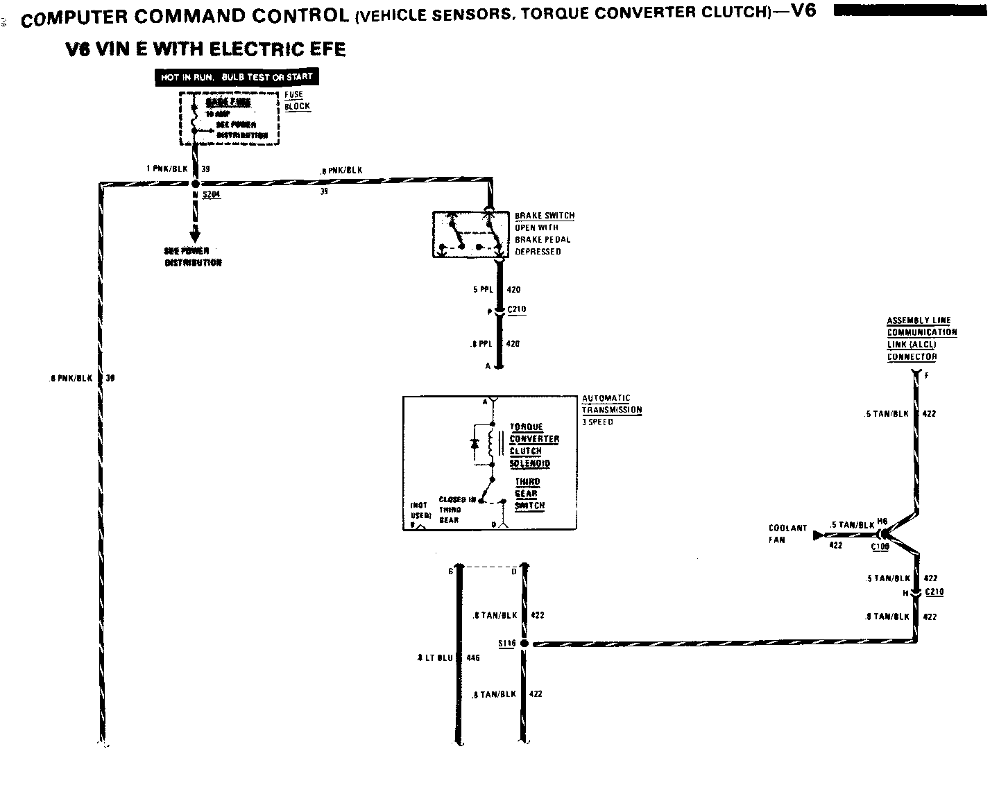
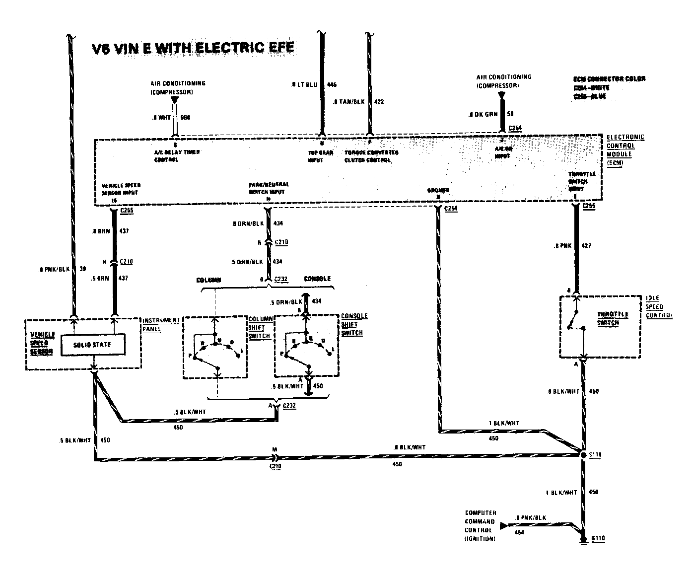
COMPUTER COMMAND CONTROL (VEHICLE SENSORS, TORQUE CONVERTER CLUTCH)-V6 SEE SECTION 6E FOR DETAILED DIAGNOSTIC PROCEDURES
COMPONENT LOCATION Page-Figure
Assembly Line Communication Link (ALCL) Connector........ On bottom of I/P, steering column........113-1 Brake Switch...................On brake pedal support...................165-2 Column Shift Switch............Lower base of steering column ...........175-1 Console Shift Switch...........Base of gear selector....................175-2 Electronic Control Module......Behind RH side of I/P............ .......102-1 Idle Speed Control.............Ahead of LH side of carburetor...........237-2 C100 (34 cavities).............LH cowl, behind shock tower..............167-1 C210 (15 cavities).............Behind glove box, below support bracket..136-1 C232 (2 cavities)............. Behind I/P, above steering column........191-1 G110...........................Top of engine, left of generator........ 237-1 S116.......................... CCC harness, below distributor ..........231-2 S118 ..........................CCC harness, left of distributor ....... 237-1 S204 ..........................I/P harness, near ash tray...............183-1
CIRCUIT OPERATION
The Torque Converter Clutch eliminates torque converter slippage and increases the efficiency of the automatic transmission assembly.
The ELECTRONIC CONTROL MODULE (ECM) controls Torque Converter Clutch engagement by controlling the ground connection to the TORQUE CONVERTER CLUTCH SOLENOID. The ECM grounds the TORQUE CONVERTER CLUTCH SOLENOID only when specific operating conditions are met as determined by vehicle sensor inputs to the ECM.
The VEHICLE SPEED SENSOR provides the ECM with a series of 12 volt pulses indicating vehicle speed. The COLUMN SHIFT SWITCH or CONSOLE SHIFT SWITCH closes in "Park" or "Neutral" and signals the ECM to retard ignition timing. The THIRD GEAR SWITCH closes when the car is in third gear.
When the brake pedal is depressed, the BRAKE SWITCH opens, cutting off current to the TORQUE CONVERTER CLUTCH SOLENOID. The torque converter clutch disengages. When the accelerator is released, the THROTTLE SWITCH closes. This signals the ECM to disengage the torque converter clutch. The ECM also disengages the torque converter clutch when vehicle sensor inputs indicate the need for engine torque multiplication.
COOLANT FAN-V6
COMPONENT LOCATION Page-Figure
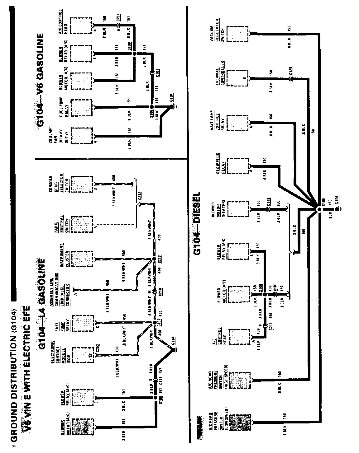
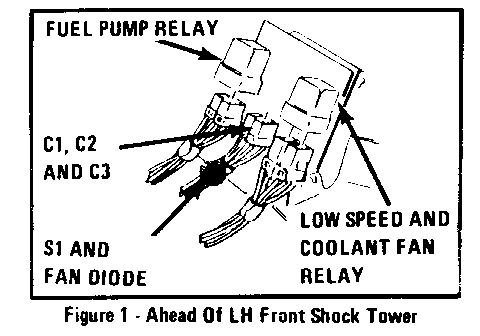
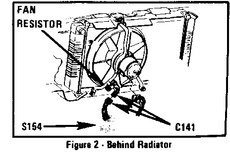
Coolant Fan Relay............. Ahead of LH shock tower, on fender...... 212-1 Coolant Fan Resistor.......... On cooling fan support bracket.......... 321-2 Coolant Fan Switch............ Top of engine near distributor.......... 212-3 Electronic Control Module..... Behind RH side of I/P .................. 136-1 Fuse Block.................... Behind RH side of I/P....................102-1 Fusible Link C................ Front of engine, near starter motor..... 212-3 High Speed Coolant Fan Relay.. Ahead of battery.........................321-1 Low Speed Coolant Fan Relay... On LH front wheel well, ahead of shock...321-1 tower C100 (34 cavities)............ LH cowl behind shock tower...............167-1 C101 (6 cavities)............. Upper center part of engine cowl.........234-4 C141 (2 cavities)............. Below cooling fan motor..................321-2 C209 (2 cavities)............. Behind I/P, near control head ...........197-1 C210 (15 cavities)............ Behind glove box, below support bracket..136-1 C211 (6 cavities)............. Behind center of I/P, near cowl grommet..197-1 G104.......................... On LH side of engine.................... 127-1 S106.......................... Engine harness, below brake fluid........182-1 reservoir S109.......................... Dash hamess, below vacuum tank.......... 234-4 S116.......................... CCC hamess, below distributor............231-2 S129.......................... Engine harness, below brake fluid........182-1 reservoir S154.......................... Engine harness, near cooling fan motor...321-2
CIRCUIT OPERATION
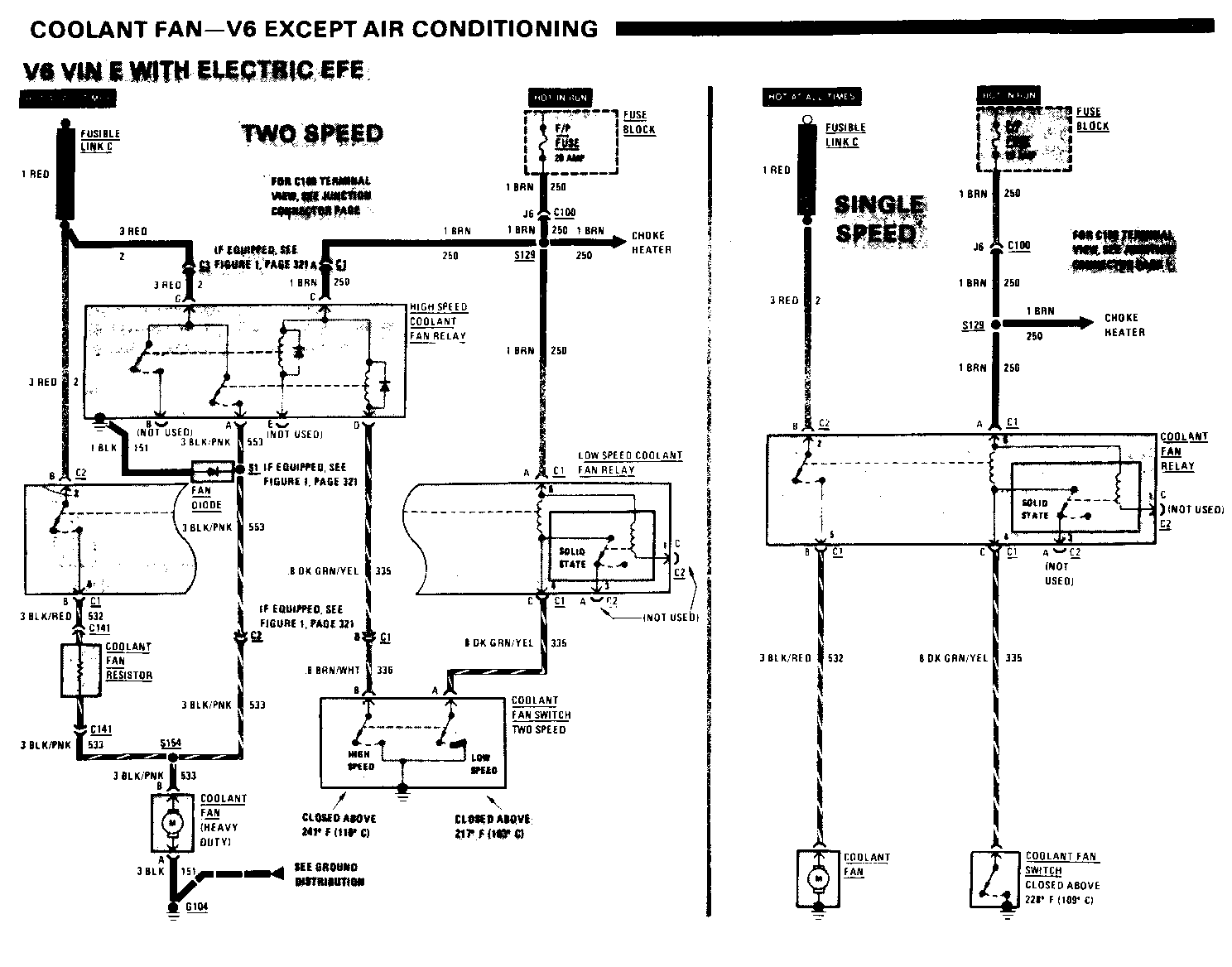
Single Speed
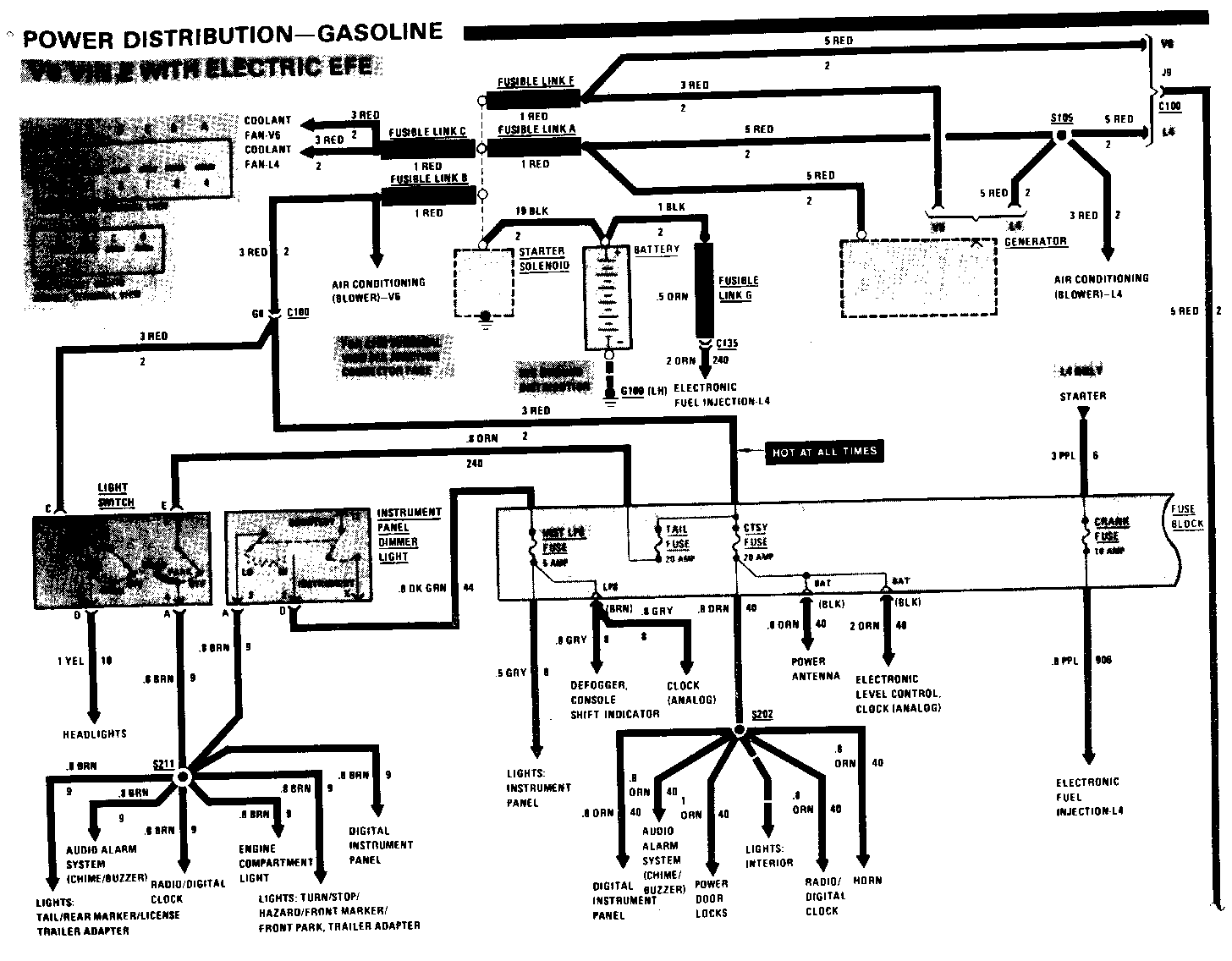
Voltage is available at all times through FUSIBLE LINK C to the COOLANT FAN RELAY contacts. With the IGNITION SWITCH in "Run," voltage is available through the F/P FUSE to the COOLANT FAN RELAY coil.
Depending on coolant temperature, the COOLANT FAN SWITCH contact will be open or closed.
With the COOLANT FAN SWITCH contact closed, current flows through the F/P FUSE, the COOLANT FAN RELAY coil, and the COOLANT FAN SWITCH contact to ground. The COOLANT FAN RELAY contact closes. Current flows through FUSIBLE LINK C, the COOLANT FAN RELAY contact, and the COOLANT FAN to ground. The COOLANT FAN operates.
Two Speed (Except Air Conditioning)
This circuit provides automatic 2-speed operation of the COOLANT FAN.
Voltage in available at all times through FUSIBLE LINK C to each contact of the LOW SPEED COOLANT FAN RELAY and the HIGH SPEED COOLANT FAN RELAY. With the IGNITION SWITCH in "Run," voltage is available through the F/P FUSE to each coil of both the LOW SPEED COOLANT FAN RELAY and the HIGH SPEED COOLANT FAN RELAY.
Depending on coolant temperature, the COOLANT FAN SWITCH will be in one of three states: 1) Both low and high speed contacts open (fan does not operate); 2) Low speed contacts closed; 3) High speed and low speed contacts closed.
With the COOLANT FAN SWITCH low speed contact closed, current flows through the F/P FUSE, the LOW SPEED COOL-ANT FAN RELAY coil and the COOLANT FAN SWITCH low speed contact to ground. The LOW SPEED COOIANT FAN RELAY contact closes. Current flows through FUSIBLE LINK C, the LOW SPEED COOLANT FAN RELAY contact, the COOLANT FAN RESISTOR, and the COOLANT FAN to ground. The COOLANT FAN operates at low speed.
With the COOLANT FAN SWITCH high speed contact closed, current flows through the F/P FUSE, the HIGH SPEED COOLANT FAN RELAY coil and the COOLANT FAN SWITCH high speed contact to ground. The HIGH SPEED COOLANT FAN RELAY contact closes. Current flows through FUSIBLE LINK C, the HIGH SPEED COOLANT FAN RELAY contact and the COOLANT FAN to ground. The COOLANT FAN operates at high speed.
COOLANT FAN-V6
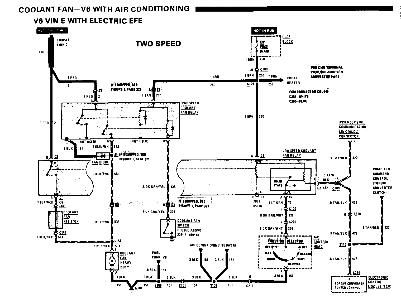
Two Speed (With Air Conditioning)
This circuit provides 2-speed operation of the COOLANT FAN.
Voltage is available at all times through the FUSIBLE LINK C to each contact of both the HIGH SPEED COOLANT FAN RELAY and the LOW SPEED COOLANT FAN RELAY. With the IGNITION SWITCH in "Run," voltage is available through the F/P FUSE to each coil of both the HIGH SPEED COOLANT FAN RELAY and the LOW SPEED COOLANT FAN RELAY.
With the FUNCTION SELECTOR in th "Max," "Norm," or "Bi-Level" position current flows through the F/P FUSE, the LOW SPEED COOLANT FAN RELA coil, and the FUNCTION SELECTOR to ground. The LOW SPEED COOLANT FAN RELAY contact closes. Current flow through FUSIBLE LINK C, the LOW SPEED COOLANT FAN RELAY contact the COOLANT FAN RESISTOR and the COOLANT FAN to ground. The COOLANT FAN operates at low speed.
With the TORQUE CONVERTE CLUTCH energized by the ELECTRONIC CONTROL MODULE, ground is applied to the solid state circuitry of the LOW SPEED COOLANT FAN RELAY. With the soli state circuitry grounded, the A/C CONTROL HEAD does not control the COOLANT FAN.
With the COOLANT FAN SWITCH contact closed, current flows through th F/P FUSE, the HIGH SPEED COOLANT FAN RELAY coil and the COOLANT FAN SWITCH to ground. The HIGH SPEED COOLANT FAN RELAY contact closes. Current flows through FUSIBLE LINK C, the HIGH SPEED COOLANT FAN RELAY contact and the COOLANT FAN to ground. The COOLANT FAN operates at high speed.
TROUBLESHOOTING HINTS
Single Speed, Two Speed and Two Speed with A/C
If COOLANT FAN doesn't run:
- Check F/P FUSE. - Check FUSIBLE LINK C. - Check that G104 is clean and tight. - Connect a jumper from COOLANT FAN RELAY coil (DK GRN/YEL WIRE) to ground. COOLANT FAN should run. - With Two Speed System, connect a jumper from the LOW SPEED COOLANT FAN RELAY coil (DK GRN/YEL wire or, with Air Conditioning, LT GRN wire) to ground. COOLANT FAN should run at slow speed. - With Two Speed System, connect a jumper from the HIGH SPEED COOLANT FAN RELAY coil (BRN/ WHT wire or, with Air Conditioning, DK GRN/YEL wire) to ground. The COOLANT FAN should run at high speed. - With Two Speed fans, check the COOLANT FAN RESISTOR for continuity. - In cars with Air Conditioning, check the TAN/BLK wire at the LOW SPEED COOLANT FAN RELAY for 12 volts.
If COOLANT FAN runs whenever IGNITION SWITCH is in "Run":
- Check COOLANT FAN SWITCH to see if switch is closed at all times.
- Check FUNCTION SELECTOR to see if it is grounded at all times.
- Check COOLANT FAN RELAY, LOW SPEED or HIGH SPEED COOLANT FAN RELAY for stuck contacts.
AIR CONDITIONING (COMPRESSOR)
COMPONENT LOCATION Page-Figure
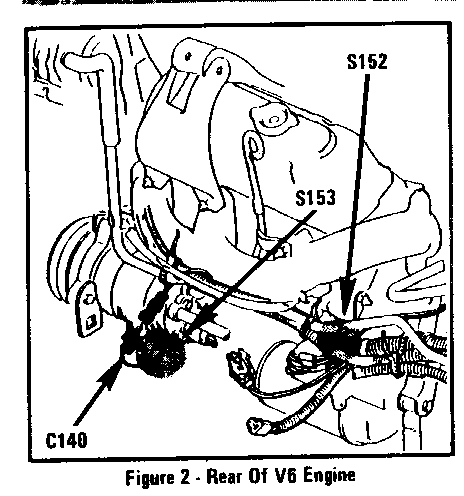
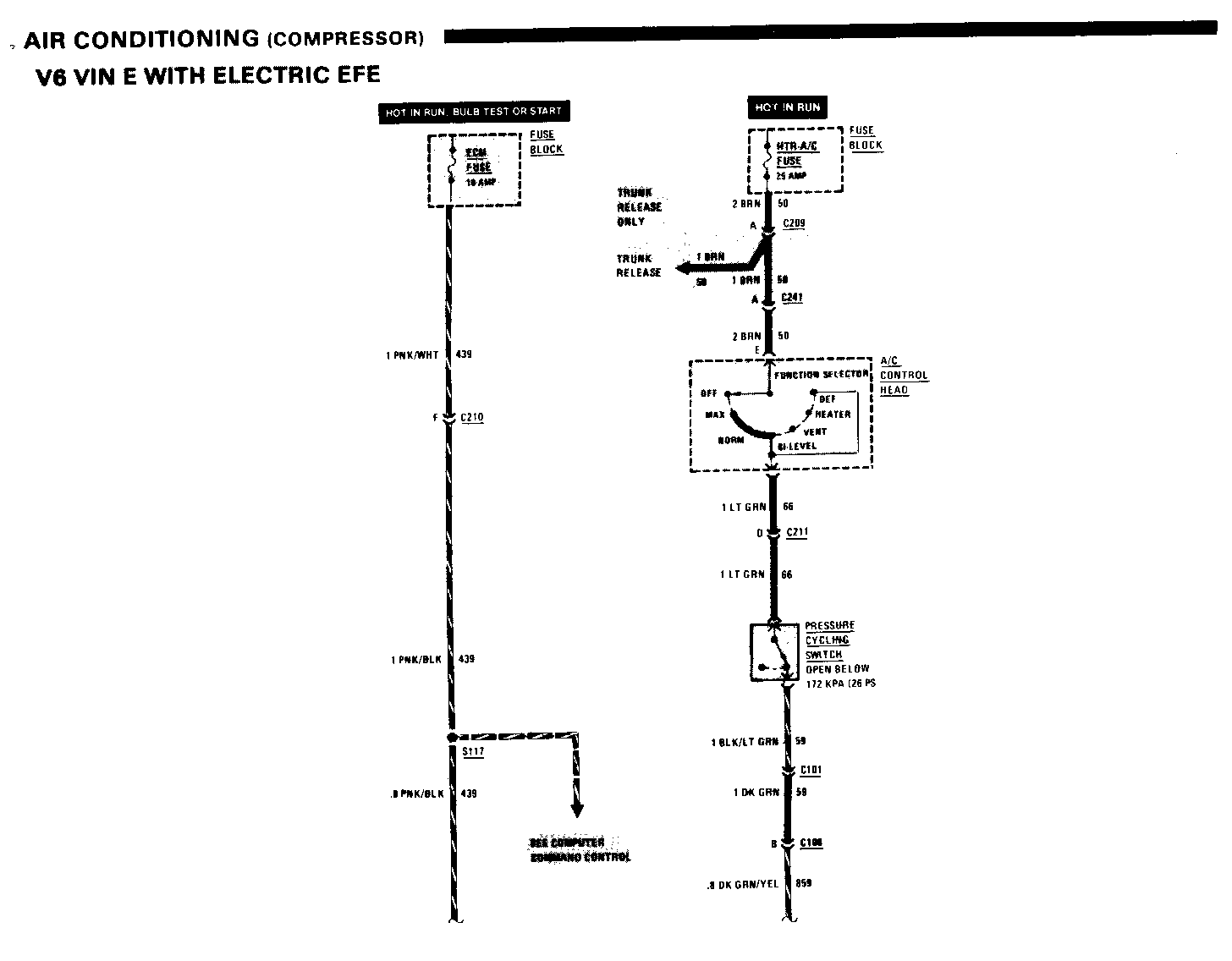
A/C Compressor Clutch.......... Part of A/C compressor............... 236-1 A/C Delay Relay................ Upper RH comer of engine cowl.........231-2 A/C High Pressure Cut-Out Switch........................ Left of A/C compressor............... 236-1 Electronic Control Module...... Behind RH side of I/P.................136-1 Fuse Block..................... Behind RH side of I/P ................102-1 Power Steering Cut-Out Switch...Front of engine Pressure Cycling Switch........ Engine cowl, near receiver/drier..... 234-4 C101 (6 cavities).............. Upper center part of engine cowl......234-4 C108 (2 cavities).............. Front of engine, below exhaust........236-2 manifold C140 (1 cavity()3 speed)....... Rear of engine, near A/C compressor.. 303-2 C209 (2 cavities).............. Behind I/P, near control head........ 197-1 C210 (15 cavities)..............Behind glove box, below support...... 136-1 bracket C211 (6 cavities).............. Behind center of I/P, near grommet....197-1 C241 (2 cavities).............. Behind I/P, below control head....... 197-1 S117............................CCC harness, below distributor........231-2
CIRCUIT OPERATION
With the IGNITION SWITCH in "Run," voltage is applied through the HTR-A/C FUSE to the A/C CONTROL HEAD.
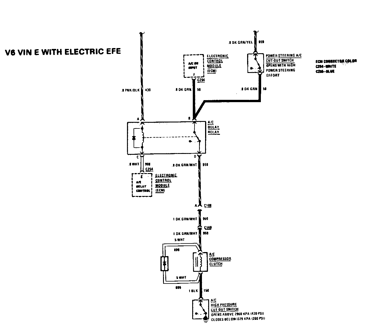
With the control head in "Max," "Norm," "Bi-Level," or "Def," current flows through the FUNCTION SELECTOR, the PRESSURE CYCLING SWITCH, the POWER STEERING CUT-OUT SWITCH, the normally closed contacts of the A/C DELAY RELAY, the A/C COMPRESSOR CLUTCH, and the A/C HIGH PRESSURE CUT-OUT SWITCH to ground. The A/C COMPRESSOR CLUTCH operates.
The POWER STEERING CUT-OUT SWITCH opens to cut off the A/C COMPRESSOR. This relieves the engine load when the power steering requires maximum effort.
The A/C HIGH PRESSURE CUT-OUT SWITCH opens only if pressure within the air conditioner becomes too high for safety (2960 kPa, or 430 psi).
The PRESSURE CYCLING SWITCH opens below 172 kPa (26 psi) to prevent evaporator freeze-up. Terminal J of the ELECTRONIC CONTROL MODULE (ECM) senses the position of the PRESSURE CYCLING SWITCH. When the PRESSURE CYCLING SWITCH closes to power the compressor, the ECM sends "command" signals to the engine controls to adjust for the A/C load on the engine. The ECM delays the compressor operation by grounding terminal E of the ECM. The A/C DELAY RELAY contacts open, disconnecting the A/C COMPRESSOR CLUTCH. After a programmed delay, the ECM ungrounds terminal E, which stops current through the A/C DELAY RELAY. The relay contacts close and power is applied to the compressor clutch. Above about 1400 RPM, no delay is programmed.
When the current to the A/C COMPRESSOR CLUTCH coil is cut off, the field surrounding the coil collapses. This creates unwanted voltage spikes. The diode across the coil suppresses these spikes.
TROUBLESHOOTING HINTS
If A/C COMPRESSOR CLUTCH will not operate, but BLOWER MOTOR runs:
- Check for voltage through PRESSURE CYCLING SWITCH to A/C COMPRESSOR CLUTCH.
- Check continuity of A/C HIGH PRESSURE CUT-OUT SWITCH.
General Motors bulletins are intended for use by professional technicians, not a "do-it-yourselfer". They are written to inform those technicians of conditions that may occur on some vehicles, or to provide information that could assist in the proper service of a vehicle. Properly trained technicians have the equipment, tools, safety instructions and know-how to do a job properly and safely. If a condition is described, do not assume that the bulletin applies to your vehicle, or that your vehicle will have that condition. See a General Motors dealer servicing your brand of General Motors vehicle for information on whether your vehicle may benefit from the information.
