DIGITAL INSTRUMENT CLUSTER 1983 CENTURYS AND RIVIERAS

MODELS AFFECTED: 1983 Centurys and Rivieras
Buick is pleased to announce an exchange repair program for the optional !983 digital instrument cluster on Buick Century and Riviera cars. This program, effective September 15, 1982, provides repaired digital instrument clusters in exchange for inoperative units at a cost substantially below the cost of new replacement parts.
Digital Instrument Clusters will be serviced with the exchange units indicated below. An exchange unit consists of processor and driver circuit boards assembled to a dial. These exchange units are available from the three authorized AC-Delco Service Centers listed in this bulletin.
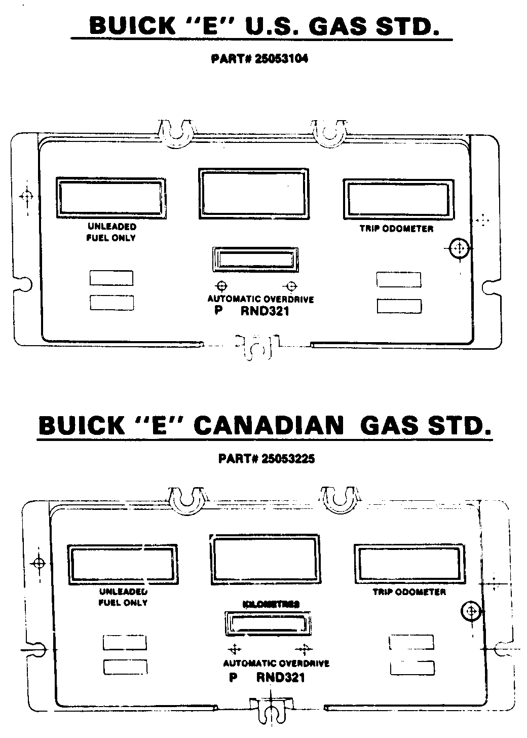
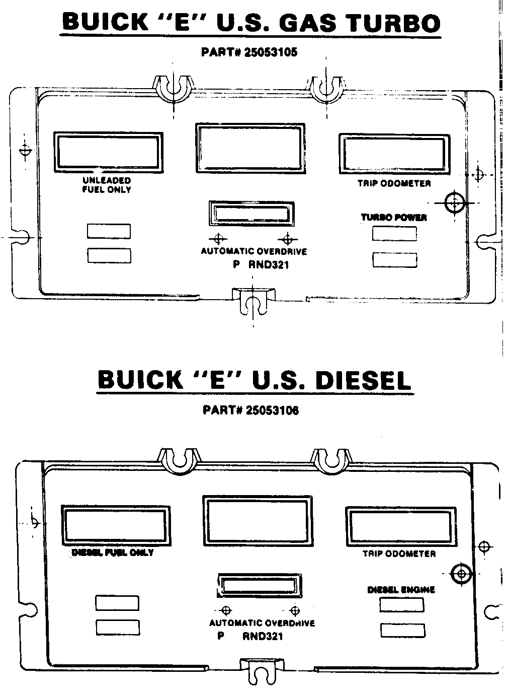
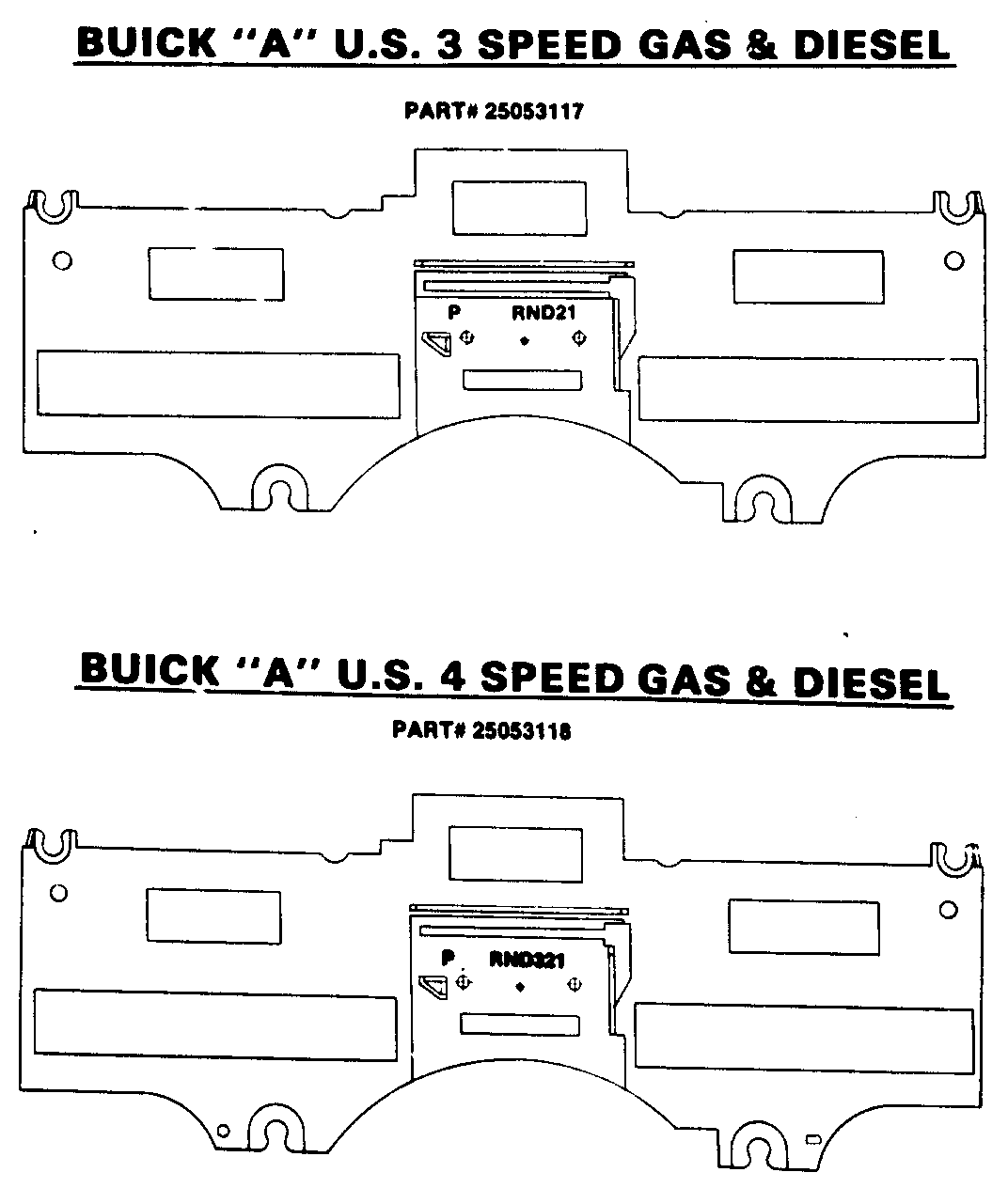
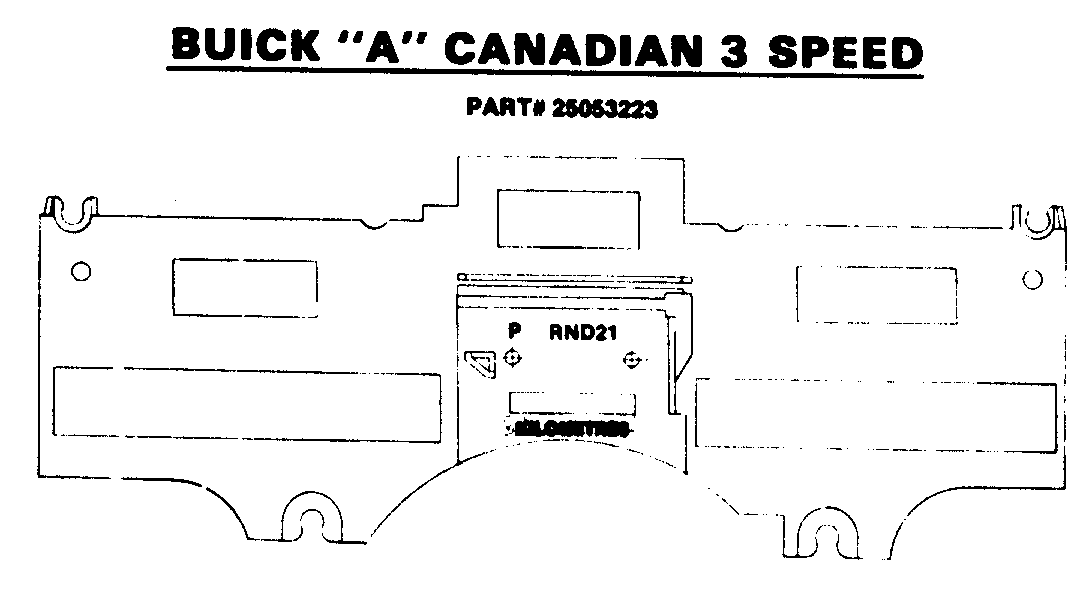
Exchange Unit Part No. Application -------- ----------- 25053104 Buick Riviera, U.S. - Gas - Std. 25053105 Buick Riviera, U.S. - Gas - Turbo 25053106 Buick Riviera, U.S. - Diesel 25053225 Buick Riviera, Canadian - Gas - Std. 25053117 Buick Century, U.S. - 3 Spd. - Gas & diesel 25053118 Buick Century, U.S. - 4 Spd. - Gas & Diesel
25053223 Buick Century, Canadian - 3 Spd.
An advance exchange Digital Instrument Cluster may be obtained by telephoning one of the three repair centers. (For your convenience, all three centers have toll free numbers). The requested exchange unit will be shipped via UPS within 24 hours, along with a memo billing for the price of the exchange unit. The memo billing will be cancelled upon receipt of the inoperative unit and a properly completed ACD - 1078 claim fom. For out of warranty service, the service center will bill you for the cost of the repair upon receipt of the inoperative unit.
Please adhere to the following procedure when a vehicle requires dealer service for an inoperative digital cluster:
1. Follow the diagnostics procedure in the Service Manual precisely and completely. Many conditions perceived by the observer to be in the digital cluster are actually problems with the remote sensors and connectors. Proper diagnostics will identify the source of the problem and avoid the unnecessary removal and shipping of functional clusters to The AC-Delco Service Centers. For your reference, a copy of Riviera cluster diagnostics from the 1983 Buick Service Manual is attached to this bulletin.
2. When diagnostics are complete and the fault is determined to be located in the digital cluster, call one of the service centers (See Page 3), and request the appropriate exchange unit as listed. Pictorial displays of 1983 Buick digital clusters are shown on Pages 4 through 7 of this bulletin to aid you in making the correct determination.
3. After the exchange unit is received from the repair center, remove the inoperative cluster by following the Removal and Installation Procedures contained in this bulletin.
4. Remove the exchange unit from the reuseable shipping container and attach the speedometer mechanism to the exchange unit. Reassemble the shift indicator lens, and trip odometer knob. Install in vehicle. Use care in handling the exchange cluster. Hands must be free of dirt and grease. Avoid touching electronic components in the cluster, as static electricity discharge can affect electronic components.
5. Pack the inoperative cluster removed from the vehicle in the reuseable shipping container, together with all five copies of the completed ACD-1078 warranty fom. To assist the service center in isolating the problem, be sure to include a description of the cluster problem in the "Nature of Problem" area on the ACD-1078 form. Failure to return the inoperative cluster in the special reuseable container will result in a $10.00 container replacement fee to your dealership.
6. Enclosed in the reuseable container is a pre-addressed shipping label. Attach this label to the outside of the box and ship immediately to the service center. The dealer copy of the ACD-1078 warranty fom will be returned to you and the memo billing will be cancelled upon receipt of the inoperative unit at the repair center.
The success of the Digital Cluster Exchange Program is dependent upon return of inoperative clusters to The AC-Delco Service Centers. Operation is essential to maintain sufficient exchange stock at these service centers.
Authorized AC-Delco Service Centers (Digital Cluster Repair Program)
West Auto Electric Radio 1841 W. Commonwealth Fullerton, CA 92633 (714) 871-7426 1-800-321-6969 - Outside California 1-800-321-6970 - California Only East United Radio Service 2949 Erie Blvd, East Syracuse, NY 13224 (315) 446-5570 1-800-448-0944 - Outside New York 1-800-962-0901 - New York Only Midwest Specmo Instrument Service 2344 N. Woodward Avenue Royal Oak, MI 48073 (313) 399-5645 1-800-545-7911 - Outside Michigan 1-800-545-7910 - Michigan Only
ELECTRONIC CLUSTER
CIRCUIT OPERATION
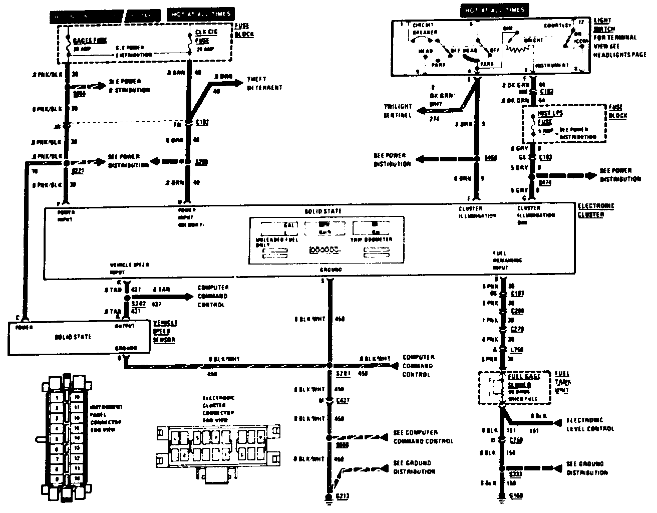
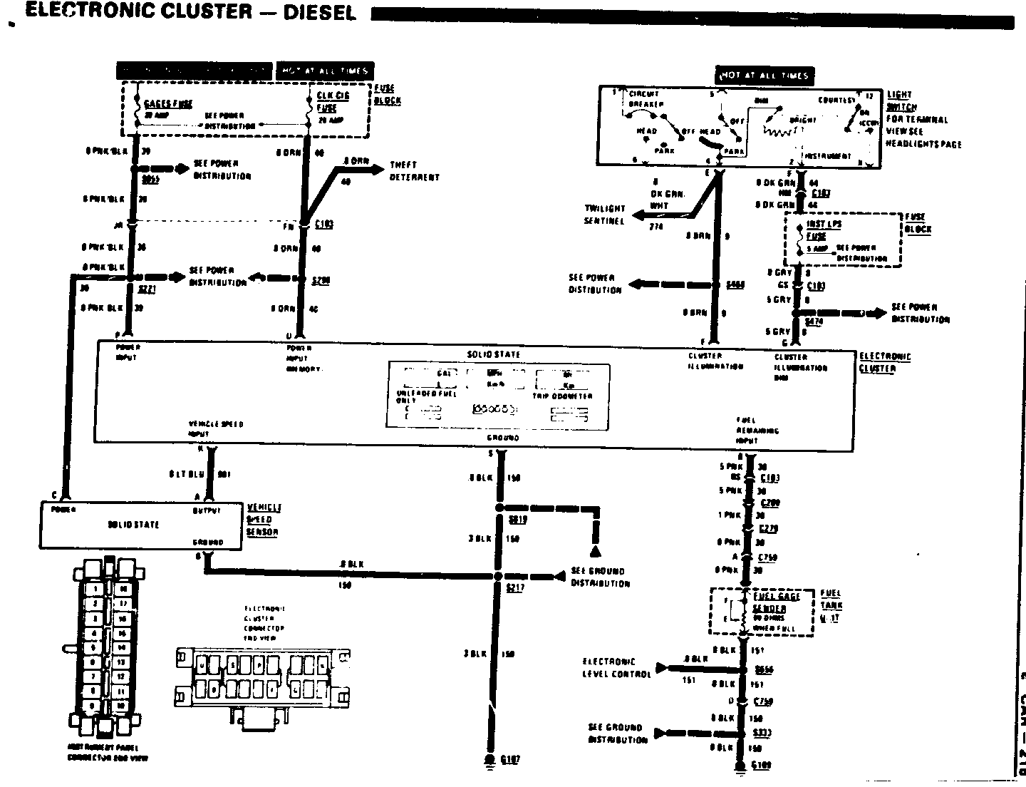
The ELECTRONIC CLUSTER uses a digital microprocessorr to develop data for fuel supply, trip distance and vehicle speed. The ELECTRONIC CLUSTER also contains conventional indicators and a mechanical total miles odometer.
Current flows at all times through the CLK-CIG FUSE and the ORN wire (40), to the ELECTRONIC CLUSTER. This power retains the TRIP ODOMETER memory when the IGNITION SWITCH is "Off." With the IGNITION SWITCH in "Run," "Bulb Test" or "Start,"voltage is applied through the GAGES FUSE to the ELECTRONIC CLUSTER. One second later all digital display segments come on together as a display test. The display test lasts up to 3 seconds. The displays then show their current data. When the reset button is turned, the digital displays change betwwn English units (MI. MPH and GAL) and Metric units (km. km/h,L).
With the LIGHT SWITCH in "Off," no voltage in applied to the BRN wire (9), and the digital display shows maximum brightness. With the LIGHT SWITCH in "Park" or "Head," battery voltage is applied through the BRN wire (9) to the CLUSTER ILLUMINATION input at the ELECTRONIC CLUSTER. Voltate is also applied through the INSTRUMENT PANEL DIMMER, the INST LPS FUSE and the GRY wire (8) to the ELECTRONIC CLUSTER. The voltage on the GRY wire (8) varies as the dimmer is moved. The digital display illumination varies along with the voltage of the GRY wire (8). (The display dims as the GRY wire voltage is reduced.)
COMPONENT LOCATION Page-Figure ------------------ ----------- Fuel Tank Unit Top center of fuel tank 595.5 Fuse Block Under LH side of I/P 406-1 Vehicle Speed Sensor Attached to back RH side of duster carrier assembly 430-2 C103 (44 cavities) Behind I/P, to left of steering column 485-2 C209(11 cavities) Attached to LH side of fuse block 523-2 C279 (7 cavities) In trunk, behind LH rear wheel well 475-1 C759 (6 cavities) Behind center of rear bumper, near tank 475-2 G107 Behind I/P, below RH side of radio 530-1 G169 Intrunk, near LH rear lights 475-1 S217 I/P harness, above LH side of radio 530-1 S221 I/P harness, to left of radio 530-1 S298 I/P harness above light switch 485-2 S333 Rear lights harness, near LH back up light 475-2 S468 Dash harness, abouve fuse block 523-2 S474 I/P harness, left of steering column 485-2 S655 Dash harness, above fuse block 523-2 S656 Rear lights harness, left of license plate 475-2 S819 I/P harness, left of steering column 485-2
Speedometer Display
With IGNITION SWITCH in "Run," "Bulb Test" or "Start," current flows throught the GAGES FUSE and the VEHICLE SPEED SENSOR, to ground. As the car moves, the speedometer cable turns the shaft to the mechanical total miles odometer. An infra-red light shines from the VEHICLE SPEED SENSOR onto a rotating field plate in the speedometer. The field plate reflects pulses of light to the VEHICLE SPEED SENDER. These pulses of light are converted by a photocell to electrical pulses. The VEHICLE SPEED SENSOR sends these pulses to the ELECTRONIC CLUSTER (connector cavity K0. The pulse rate (speed) is displayed as MPH or km/h.
Trip Odometer Display
The ELECTRONIC CLUSTER display adde up the number of reflected light pulses (see preceding paragraph) and advances the TRIP ODOMETER mileage display. When the reset button in pressed,the TRIP ODOMETER returne to "0.0" display. The TRIP ODOMETER displays tenths of miles until "999.9" and miles from "1000" to "3999". After "3999" the TRIP ODOMETER returns to a "0.0" display.
Fuel Gage Display
Current from the ELECTRONIC CLUSTER display flows through the PNK wire (30), the FUEL TANK UNIT and the BLK wire (150) to ground G169.
The resistance of the FUEL SENDER changes with the amount of fuel in the tank. With a full tank the resistance in 90 ohms, and with an empty tank the resistance is less than 1 ohm.
The digital microprocessorr is programmed to account for battery voltage changes. Therefore, changes in battery voltage do not affect the FUEL GAGE reading.
The FUEL GAGE shown an "F" when the tank in full. As the tank empties, the display decreases in whole numbers from "17" gallons ("64" liters) to "2" gallons or "2" liters. Below 2 gallons or liters, the FUEL GAGE shows an "E" display. When the tank is almost empty, the "E" flashes.
If an open (105 ohms and above) occure in the FUEL TANK UNIT circuit, the FUEL GAGE displays flashing bars ("-").
CAUTION:
Before removing ELECTRONIC CLUSTER, turn IGNITION SWITCH to "Off" and disconnect negative battery cable. Caution: Whenever handling pressurized halogen instrument panel illumination bulbs, wear protective eyeglasses and clothing and dispose of bulbs with proper care.
CAUTION:
Be careful when handling ELECTRONIC CLUSTER as damage may occur.
ELECTRONIC CLUSTER COMPLAINTS: Page ------------------------------ ---- Verify Customer Complaint 218 All Digital Displays Show High Values 218 Electronic Cluster Shows Digit Display Error 218 Electronic Cluster Does Not Light or Dim 218 Speedometer and Trip 0dometer Do Not Wor 219 Speedometer or Trip 0dometer Does Not Work 219 Fuel Gage Displays 220 Fuel Gage Displays Flashing "E" with Fuel in Fuel Tank 221 Fuel Gage is Not Accurate 222 TEXT ZONE
TROUBLESHOOTING HINTS
VERIFY CUSTOMER COMPLAINT:
1. Turn IGNITION SWITCH to "Run."
2. All digital displays are blank for one second.
3. All display segments light for up to three seconds (display check).
4. Digital displays then show fuel level, speed, and trip odometer distance.
ALL DIGITAL DISPLAYS SHOW HIGH VALUES:
1. Check position of "E/M" (English/Metric) switch.
2. Advise customer of proper operation of switch.
ELECTRONIC CLUSTER SHOWS DIGIT DISPLAY ERROR:
One or more digits in "Segment Check" do not light, except leading zeros. Leading zeros are not displayed.
1. Turn IGNITION SWITCH to "Off."
2. Replace ELECTRONIC CLUSTER
3. Turn IGNITION SWITCH to"Run."
- Check operation of ELECTRONIC CLUSTER
ELECTRONIC CLUSTER DOES NOT LIGHT OR DIM:
1. Turn IGNITION SWITCH to "Off".
2. Remove ELECTRONIC CLUSTER
- Check BLK ground wire between cluster connector pin S and body metal ground.
3. Turn IGNITION SWITCH to "Run"/
- Measure voltage to body ground (See next page for chart):
4. Turn IGNITION SWITCH to "Off".
5. Replace ELECTRONIC CLUSTER PANEL
6. Turn IGNITION SWITCH to "Run."
- Check operation of ELECTRONIC CLUSTER
SPEEDOMETER AND TRIP ODOMETER DO NOT WORK:
1. Check operation of mechanical odometer by watching odometer increase while driving several tenths of a mile.
2. Remove ELECTRONIC CLUSTER
- Remove VEHICLE SPEED SENSOR connector (3 cavities) from VEHICLE SPEED SENSOR.
3. Check ground BLK wire from VEHICLE SPEED SENSOR connector to body metal ground.
4. Check ground BLK wire between cluster connector pin S and body metal ground.
5. Turn IGNITION SWITCH to "Run".
- Check PNK/BLK wire at VEHICLE SPEED SENSOR pin C for 12 volts.
- Measure voltages to body metal ground (SEE CRART BELOW):
6.Turn IGNITION SWITCH to "Off."
- Reconnect VEHICLE SPEED SENSOR connector to VEHICLE SPEED SENSOR.
- Connect 10.000 ohm 1 watt resistor between cluster connector pin K and cluster connector pin P with clip leads.
- Insert small screwdriver into speedometer frame neck on back of ELECTRONIC CLUSTER
7. Turn IGNITION SWITCH to "Run."
- Measure voltage between cluster connector pin K and body metal ground.
- Turn screwdriver slowly. Voltage should alternate between 0 to 1.5 volts and 9.6 to 12 volts.
8. If no voltage measured, replace VEHICLE SPEED SENSOR.
9. If proper voltage measured, replace ELECTRONIC CLUSTER.
10. Turn IGNITION SWITCH to "Off."
- Remove 10,000 ohm resistor and clip leads.
11. Install ELECTRONIC CLUSTER.
12. Turn IGNITION SWITCH to "Run."
- Check operation of ELECTRONIC CLUSTER.
SPEEDOMETER OR TRIP ODOMETER DOES NOT WORK
1. Turn IGNITION SWITCH to "Off".
2. Replace ELECTRONIC CLUSTER.
3. Turn IGNITION SWITCH to "Run."
- Check operation of ELECTRONIC CLUSTER.
ELECTRONIC INSTRUMENT PANEL VOLTAGE CHECK
CLUSTER IGNITION SWITCH LIGHT SWITCH I/P DIMMER* CONNECTOR PIN "OFF" "Run" "Off" "Park" "Dim" "Bright" --- ----- ----- ----- ------ ----- --------- G 0 12 volts volts U 12 12 12 12 12 12 volts volts volts volts volts volts P 0 12 volts volts F 0 12 volts volts
FUEL GAGE DISPLAYS "-"
A display of "--" means that the FUEL SENDER circuit resistance is more than 105 ohms.
1. Disconnect C279 (7 cavities) located in trunk behind LH rear wheel well.
2. Connect forwad PNK wire at C279 with clip lead to body metal ground.
3. Turn IGNITION SWITCH to "Run." FUEL GAGE should show flashing "E".
4. If "E" flashes, check PNK wire and BLK wire to FUEL TANK UNIT, ground G169 and FUEL SENDER (part of FUEL TANK UNIT) on Fuel Tank.
5. If "-" is still displayed, turn IGNITION SWITCH "Off".
- Remove clip lead.
- Reconnect C279.
6. Disconnect C209 (11 cavities), located on left side of FUSE BLOCK under the Instrument Panel.
- Connect clip lead between forward PNK wire at C209, and body metal ground.
7. Turn IGNITION SWITCH to "Run."
8. If flashing "E" is displayed, check C209, C279 and PNK wire between connectors.
9. If "--" is still displayed, turn IGNITION SWITCH to "Off".
- Remove clip lead. - Reconnect C209.
10. Disconnect C103 (44 cavities) located behind Instrument Panel, left of column.
- Connect clip lead between forward PNK wire at C103 pin B5, and body metal ground.
11. Turn IGNITION SWITCH to "Run."
12. If flashing "E" is displayed, check C 103, C209 and PNK wire between connectors.
13. If "-" still displayed, tum IGNITION SWITCH to "Off."
- Remove clip lead. - Reconnect C103.
14. Remove ELECTRONIC CLUSTER
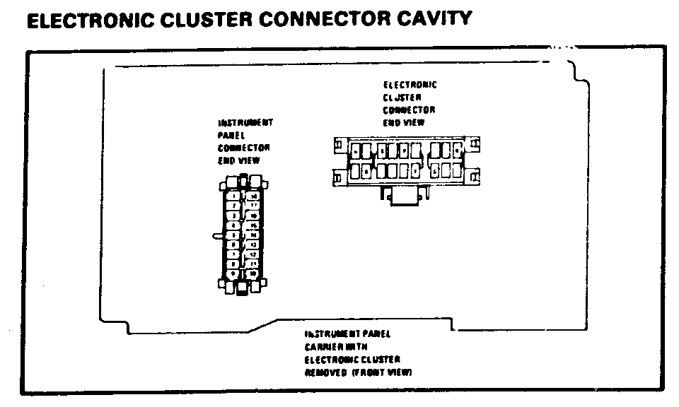
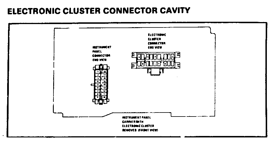
- Check seating of CLUSTER CONNECTOR in instrument panel carrier.
15. Measure voltages to body metal ground (SEE CHART ON PREVIOUS PAGE)
16. Measure resistance between CLUSTER CONNECTOR pin B and body metal ground.
17. If more than 90 ohms, skip to Step 19.
- If 90 ohme or less, replace ELECTRONIC CLUSTER.
18. Turn IGNITION SWITCH to"Run."
- Check operation of new ELECTRONIC CLUSTER.
- Skip steps 19 through 21.
19. If resistance is more than 90 ohms, check PNK wire between CLUSTER CONNECTOR pin B and C103 pin B5.
20. Repair wires or connectors.
- Reinstall ELECTRONIC CLUSTER.
21. Check operation of ELECTRONIC CLUSTER.
FUEL GAGE DISPLAYS FLASHING "E" WITH FUEL IN FUEL TANK:
Display shows less than a gallon or 2 liters of fuel in fuel tank.
1. Turn IGNITION SWITCH to "Off".
- Disconnect C279 (7 cavities) located in trunk behind LH rear wheel well.
2. Turn IGNITION SWITCH to "Run." FUEL GAGE shows "-."
3. Turn IGNITION SWITCH to "Off." Measure resistance of rearward PNK wire between C279 and body metal ground.
4. With full fuel tank, resistance should be 90 ohms.
- If not, repair wiring, check G169, or replace FUEL SENDER (part of FUEL TANK UNIT)
5. If flashing "E" still displayed, turn IGNITION SWITCH to"Off."
- Reconnect C279.
6. Disconnect C209 (11 cavities), located on left side of FUSE BLOCK under the Instrument Panel.
- Turn IGNITION SWITCH to "Run."
- FUEL GAGE should show "--"
7. Turn IGNITION SWITCH to "Off." Measure resistance of rearward PNK wire between C209 and body metal ground.
8. With full fuel tank, resistance should be 90 ohms.
- If not, check C209, C279 and PNK wire between connectors.
9. If flashing "E" is still displayed, turn IGNITION SWITCH to "Off"
- Reconnect C209.
10. Disconnect C103 (44 cavities) located behind Instrument Panel, left of steering column.
- Turn IGNITION SWITCH to "Run."
- FUEL GAGE should show "--".
11. Turn IGNITION SWITCH to "Off". Measure resistance of rearward PNK wire between C103 pin B5 and body metal ground.
12. With full fuel tank, resistance should be 90 ohms.
- If not, check C103, C209 and PNK wire between connectors.
13. If flashing "E" is still displayed, turn IGNITION SWITCH to "Off."
- Reconnect C103.
14. Remove ELECTRONIC CLUSTER.
- Check seating of CLUSTER CONNECTOR in instrument panel carrier.
15. Measure resistance between CLUSTER CONNECTOR pin B and body metel ground.
16. With full fuel tank, resistance should be 90 ohms.
- If not, check PNK wire between C201 pin B and C103 pin B5.
17. Measure voltage to body metal ground (SEE CHART BELOW).
18. Reinstall ELECTRONIC CLUSTER.
19. Turn IGNITION SWITCH TO "Run".
- Check operation of ELECTRONIC CLUSTER.
ELECTRONIC CLUSTER VOLTAGE CHECK
CLUSTER IGNITION SWITCH LIGHT SWITCH I/P DIMMER * CONNECTOR PIN "Off" "Run" "Off" "Park" "Dim" "Bright" --- ----- ----- ----- ------ ----- --------- G 0 12 volts volts U 12 12 12 12 12 12 volts volts volts volts volts volts P 0 12 volts volts F 0 12 volts volts
Fuel Gage is Not Accurate:
1. Turn IGNITION SWITCH to "Off".
- Disconnect C279 (7 cavities) located in trunk behind Lh rear wheel well.
2. Connect GG4 tester between forward PNK wire at C279 and body metal ground.
3. Set GG4 tester to zero ohms.
- Turn IGNITION SWITCH to "Run". - FUEL GAGE should show flashing "E". - Set GG4 tester to 45 ohms. - FUEL GAGE should show "8.5" gallons ("32"liters). - set GG4 tester to 90 ohms. - FUEL GAGE should show "F".
4. If FUEL GAGE is accurate, turn IGNITION SWITCH to "Off".
- Check PNK wire and BLK wire to FUEL TANK UNIT, G169 and FUEL SENDER (part of FUEL TANK UNIT) on fuel tank.
5. If FUEL GAGE is not accurate, reconnect C279.
6. Disconnect C209 (11 cavities), located on left side of FUSE BLOCK, under the Instrument Panel.
- Connect GG4 tester between forward PNK wire at C209, and body metal ground.
7. Set GG4 tester to 0 ohms.
- Turn IGNITION SWITCH to "Run". - FUEL GAGE should show flashing "E". - Set GG4 tester to 45 ohms. - FUEL GAGE should show "8.5" gallons (32 liters). - Set GG4 tester to 90 ohms. - FUEL GAGE should show "F".
8. If FUEL GAGE is accurate, turn IGNITION SWITCH to "Off".
- Check PNK wire between C209 and C279.
9. If FUEL GAGE is not accurate, reconnect C209.
10. Disconnect C103 (44 cavities) located behind Instrument Panel, left of steering column.
- Connect GG4 tester between forward PNK wire at C103, pin B5, and body metal ground.
11. Set GG4 tester to zero ohms.
- Turn IGNITION SWITCH to "Run." - FUEL GAGE should show flashing "E." - Set GG4 tester to 45 ohms. - FUEL GAGE should show "8.5" gallons ("32" liters). - Set GG4 tester to 90 ohms. - FUEL GAGE should show "F".
12. If FUEL GAGE is accurate, turn IGNITION SWITCH to "Off". - Check PNK wire between C103 pin B5 and C209.
13. If FUEL GAGE is not accurate, remove ELECTRONIC CLUSTER. - Check seating of CLUSTER CONNECTOR in instrument panel carrier.
14. Measure voltages to body metal ground (SEE CHART ON PREVIOUS PAGE).
15. Check PNK wire between CLUSTER CONNECTOR pin B and C103 pin B5.
16. If PNK wire is okay, replace ELECTRONIC CLUSTER.
17. Turn IGNITION SWITCH to "Run".
- Check operation of ELECTRONIC CLUSTER.
1983 BUICK RIVIERA ELECTRONIC CLUSTER REMOVAL AND INSTALLATION
1. Disconnect negative battery cable.
2. Remove center trim plate by pulling straight out.
3. Remove left trim plate by pulling straight out (first remove headlamp switch knob and bezel.)
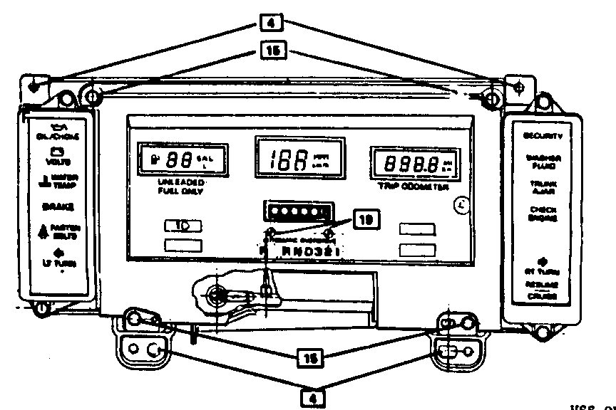
4. Remove four (4) 7mm screws that hold cluster carrier to I/P carrier (see Figure #1).
5. Disconnect speedometer cable from the cruise control transducer or transmission in order to feed cable through cowl panel so there is slack to bring cluster carrier assembly forward.
6. Disconnect shift indicator clip from steering column bowl. (For installation it may be necessary to remove two (2) 7mm screws and lower front of left I/P sound insulator.)
7. Tip the top edge of the cluster carrier assembly forward and pull forward about two inches.
8. Remove check engine bulb and socket by rotating socket and pulling out of carrier assembly.
9. Disconnect cluster harness connector by pinching lock tab and pulling out of carrier assembly.
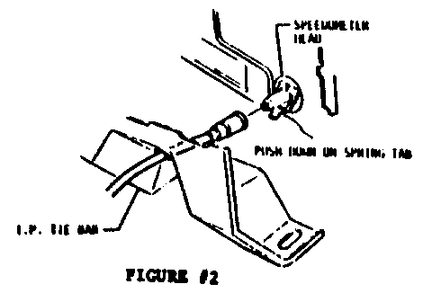
10. Disconnect speedometer cable from speedometer frame by pushing in retaining clip and pulling cable away from cluster (Figure #2).
11. Disconnect one (1) 6mm screw connecting ground strap to I/P tie bar.
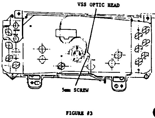
12. Pull the gear shift lever down into Low 1 and pull the cluster carrier assembly outward tipping top side out first. Pull out just far enough to gain access to the one (1) 5mm screw holding the vehicle speed sensor optic head to the back of the speedometer frame and disconnect (Figure #3).
13. Pull cluster carrier assembly all the way out.
14. Unscrew knob from trip set lever.
15. Remove four (4) 6mm screws from clear cluster lens cover to cluster carrier (see Figure #1).
16. Remove clear lens and black filler.
17. Remove spring arbd needle assembly from shift indicator,
18. Remove five (5) 6mm screws holding tube and circuit board assembly to cluster carrier. Lift tube and circuit board assembly out of cluster carrier noting the position of the gaskets covering the indicator lights.
19. Remove two (2) standard head screws from tube and circuit board face plate holding speedometer frame to tube and circuit board (see Figure #1).
20. Remove mechanical speedometer assembly.
21. To install, reverse Removal Procedures.
General Motors bulletins are intended for use by professional technicians, not a "do-it-yourselfer". They are written to inform those technicians of conditions that may occur on some vehicles, or to provide information that could assist in the proper service of a vehicle. Properly trained technicians have the equipment, tools, safety instructions and know-how to do a job properly and safely. If a condition is described, do not assume that the bulletin applies to your vehicle, or that your vehicle will have that condition. See a General Motors dealer servicing your brand of General Motors vehicle for information on whether your vehicle may benefit from the information.
