CAMPAIGN: ENGINE COOLING FAN RELAY MAY FAIL

MODELS AFFECTED: 1983 CENTURYS EQUIPPED WITH 3.0L (LK9) ENGINES
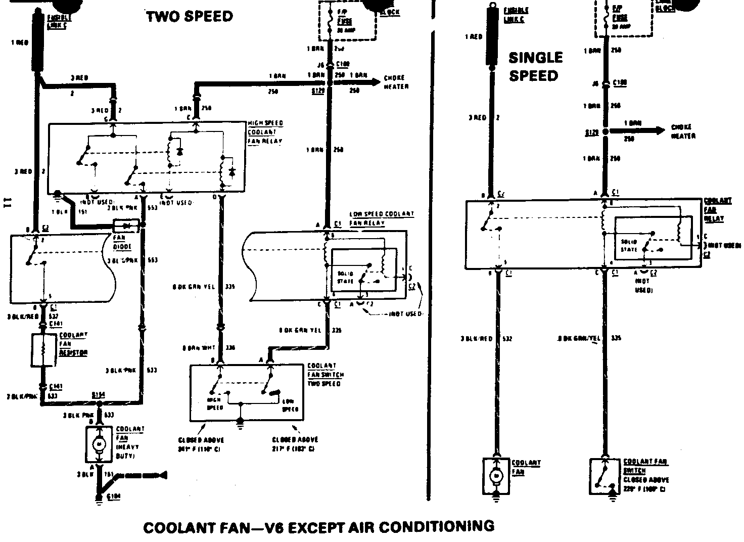
General Motors has determined that some 1983 Buick Centurys were assembled with an engine cooling fan relay that may fail. A failed relay can cause the fan motor to continue to operate with the ignition switch in the "OFF" position, resulting in a discharged battery.
DEALER CAMPAIGN RESPONSIBILITY
To prevent the possibility of this from occurring, dealers are to perfom the following action, as instructed in the Technical Procedure of this bulletin:
- Vehicles equipped with air conditioning, replace the fan high-speed relay with a heavy duty relay.
- Vehicles equipped with heater, less heavy duty cooling, replace the fan single-speed relay with an improved relay.
- Vehicles equipped with heater and heavy duty cooling, replace both the fan high-speed and low-speed relays.
Dealers are to service all vehicles subject to this campaign at no charge to owners, regardless of mileage, age of vehicle, or ownership, from this time forward.
Whenever a vehicle subject this campaign is taken into your new or used vehicle inventory or if in your dealership for service in the future, you should take the steps necessary to be sure the campaign correction has been made before reselling or releasing the vehicle.
Owners of vehicles recently sold from your new vehicle inventory are to be contacted by the dealer, and arrangements made to make the required modification according to instructions contained in this bulletin.
VEHICLES INVOLVED
- Certain 1983 Centurys equipped with 3.0L engines (LK9, VIN E), and air conditioning, with the following serial numbers:
Assembly Plant Beginning Up To & Including -------------- --------- ----------------- Doraville DD447187 DD453144 Oklahoma City D6414727 D6417901
- Certain 1983 Centurys eguipped with 3.0L engines (LK9 VIN E) and standard heater (C-41), and Centurys with 3.0L engine and standard heater (C-41) and heavy duty cooling (V-08) within the following serial numbers:
Assembly Plant Beginning Up To & Including -------------- --------- ----------------- Doraville DD447436 DD462213 Oklahoma City D6415302 D6420354
A number of vehicles within the serial number groups had relay(s) changed at the assembly plants prior to shipment. These corrected vehicles will not be on the vehicle listing.
DEALER MATERIAL AND PARTS INFORMATION
If your dealership has vehicles involved in this campaign, you will receive a listing of all vehicles involved in this campaign shipped to your dealership, and a campaign identification label for each vehicle. The CAMP ID (campaign identification column on your vehicle listing will indicate what part kit(s) is required for each vehicle. For example:
- If 83-C05A is listed, vehicle is equipped with air conditioner (C-60). Relay Kit No. 25519237 is required.
- If 83-C05B is listed, vehicle is equipped with standard heater (C-41) only, Kit No. 25519249 is required.
- If 83-C05C is listed, vehicle is equipped with standard heater (C-41) and heavy-duty cooling (V-08), Kits No. 25519237 and 25519249 are required.
o High-Speed Relay Kit 25519237 contains the following parts:
(1) High-Speed Relay No. 25519047 (1) Jumper Harness (2) Relay Attaching Screws (2) Single-Wire Connectors (1) Two-Wire Connector
o Single/Low-Speed Relay Kit No. 25519249 contains the following parts:
(1) Single/Low-Speed Fan Relay No. 25515230 (1) 3-Way Wire Connector, Gray in Color (1) 3-Way Wire Connector, Black in Color
To ensure this part will be obtained as soon as possible, kits should be ordered from GM Parts (WDDGM) on a C.I.O. order with no special instruction code, but order on an advise code (2).
Involved vehicles are identified on computer listings. Computer listings contain the complete vehicle identification number, owner name and address data, and are furnished to the involved dealers with the campaign bulletin. Owner name and address data furnished will enable dealers to follow up with the owners involved in this campaign.
The computer listings may contain owner names and addresses obtained from State Motor Vehicle Registration Records. The use of such motor vehicle registration data for any other purpose is a violation of law in several states. Accordingly, you are urged to limit the use of this listing to the follow up necessary to complete this campaign. Any dealer not receiving a computer listing with the campaign bulletin was not shipped any involved vehicles.
TRANSFER OF VEHICLE
If a vehicle on your listing is not in your area, please forward vehicle information for this vehicle to your Buick Zone Office for handling with the proper dealer.
CHANGE OF OWNER INFORMATION
Dealers are to use the Dealer Communication System (DCS) to provide Buick Motor Division with subsequent Buick owner information. By reporting a change of owner name or address of a vehicle in campaign status over the DCS, the need to send in an S-866 fo m for that vehicle is eliminated. Terminal input instructions are covered in the DCS manual under Section 9, page 9-J01A and B.
TECHNICAL PROCEDURE
PART I - Installation of Relay and Jumper Harness Kit No. 25519237. Vehicles equipped with air conditioner or with heater and heavy duty cooling.
Some vehicles have a wire connected from the #4 terminal of the low speed-fan relay to ground at the radiator tie bar. This wire should be removed and discarded during the following procedure:
1. Raise hood and cover left fender.
2. Remove the two (2) screws that attach left sheet metal brace to radiator upper tie bar. Loosen the brace rear attaching screw and rotate brace inward to expose area over the battery.
3. Remove the positive cable from battery. Cover positive terminal on battery with electrical tape.
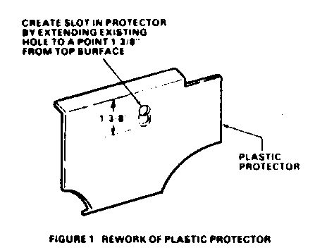
4. Remove plastic protector from upper tie bar and slot as shown in Figure 1.
5. Remove screw retaining forward lamp and battery round terminals to tie bar. Retain screw for use in Step 7. If there is a wire from the low-speed relay which is grounded by this screw, this wire should be removed and discarded.
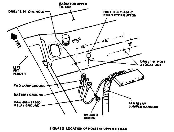
6. Drill two (2) 1/8" relay mounting holes in tie bar at locations shown in Figure 2. Use furnished relay as a template, if required.
7. Drill one (1) 13/64" hole in tie bar and attach ground wire of furnished jumper harness, along with forward lamp and battery ground wires, using screw removed in Step 5. Refer to Figure 2.
NOTICE: Electrical connectors are packed with special water resistant grease. Do not remove or wipe this grease from parts during installation of kit.
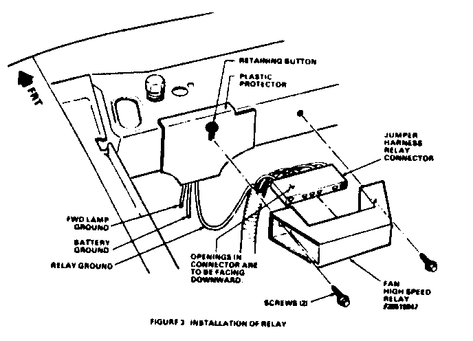
8. Reinstall plastic protector on tie bar, plug jumper harness connector on relay and attach relay to tie bar using furnished screws. Refer to Figure 3.
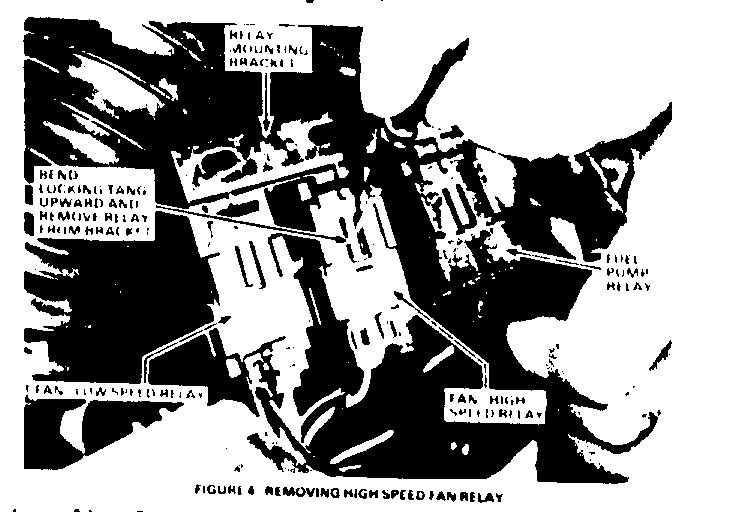
9. Remove the fuel pump, high and low-speed relay mounting bracket, from left wheel house. Remove the fan high-speed (center) relay from bracket. Refer to Figure 4.
IF VEHICLE IS EQUIPPED WITH HEATER AND HEAVY DUTY COOLING, PRIOR TO THE FOLLOWING STEP, INSTALL FAN SINGLE/LOW-SPEED RELAY AS INSTRUCTED IN STEPS 3, 4, AND 5 OF PART II OF TECHNICAL PROCEDURE.
10. Assemble relay mounting bracket to wheelhouse.
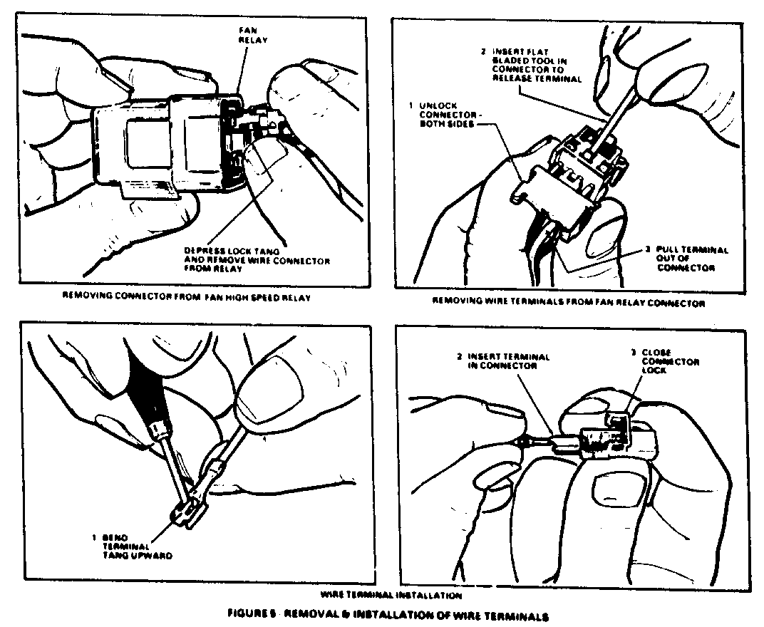
11. Remove wiring connector from fan high-speed relay. Unlock this connector, remove the four wire terminals and discard connector. Refer to Figure 5.
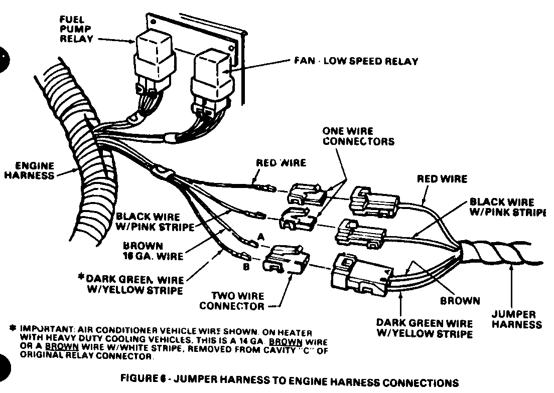
12. Install the four wire terminals removed in Step 10 into the three furnished connectors as shown, and plug the connectors into the jumper harness. Refer to Figure 6. Original wire colors must match the wire colors in the jummper harness, except for the wire removed from cavity "C" of original connector on vehicles with heater and heavy-duty cooling.
Refer to important note on Figure 6.
13. Check cooling fan high-speed relay operation by grounding the relay jumper harness dark green with yellow striped wire. Any change from the following procedure could result in damage to tne new relay.
a. Insert a jumper wire probe in relay jumper harness connector cavity "B" so that probe contacts terminal of the dark green with yellow striped wire. Refer to Figure 6.
b. Attach the other end of jumper wire to a suitable ground (sheet metal screw, battery negative terminal, etc).
c. Remove tape from battery positive terminal and reinstall positive cable.
d. Recheck to be sure you have a good connection between ground and jumper harness dark green wire with yellow stripe.
e. Place air conditioner selector lever in the "OFF" position.
f. Turn ignition switch to "ON". Fan should run at high speed. If fan does not operate, cause should be detemined and corrected.
g. Allow fan to operate for a minimum of ten (10) seconds. Turn ignition off and remove jumper wire.
14. Reinstall left sheet metal brace front attaching screws and tighten the rear attaching screw. Be sure plastic conduit is on brace in area over battery.
15. Install campaign identification label as instructed in Part III.
PART II - Installation of Single/LOW-Speed Relay Kit No. 25519249. Vehicles equipped with heater.
1. Raise vehicle hood, cover fender, and remove battery positive cable.
2. Remove the fuel pump and fan relay mounting bracket from the left wheelhouse.
3. Lift up tang on bracket and remove fan single/low-speed relay. Disconnect wiring connector from relay. Unlock connector and remove the four wire terminals and discard connector. Refer to Figures 4 and 5. (Figures 4 and 5 show procedure for high-speed fan relay. Procedure is the same for single/low-speed relay except for location of relay on bracket.)
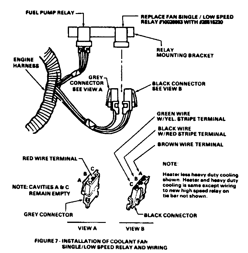
4. Insert the four wire terminals removed in Step 3 into the two connectors furnished in kit as shown in Figure 7. Plug these connectors onto new relay No. 25515230. Install relay on mounting bracket.
5. Check cooling fan single/low-speed relay operation by grounding the relay dark green with yellow striped wire.
Any change from the following procedure could result in damage to the new relay.
a. Insert a jumper wire probe in single/low-speed relay connector cavity so that probe contacts the terminal of the dark green with yellow striped wire. Refer to Figure 7.
b. Attach the other end of jumper wire to a suitable ground.
c. Connect battery positive cable.
d. Recheck to be sure you have a good connection between ground and relay dark green wire with yellow stripe.
e. Turn ignition switch to "ON". Fan should run at single/low-speed. If fan does not operate, cause should be determined and corrected.
f. Allow fan to operate for a minimum of ten (10) seconds. Turn ignition switch off and remove jumper wire.
6. Assemble relay mounting bracket to wheelhouse.
7. Install campaign identification label as instructed in Part III.
PART III - Install Campaign Identification Label
Each vehicle modified in accordance with the instructions outlined in this "Technical Procedure" will require a campaign identification label. Each label provides a space to include the campaign number, the five (5) digit dealer code of the dealer performing the campaign service, and the date vehicle was campaigned. This information may be inserted with a typewriter or ballpoint pen. When installing label, clean the surface of the radiator upper mounting support and apply the campaign label where it is readily visible.
DISPOSITION OF PARTS
Replaced parts must be held for disposition by Buick Contact Personnel. Parts must have a claim tag attached, showing the repair order and the VIN of the vehicle from which they were removed.
WARRANTY INFORMATION
Dealers are to submit each campaigned vehicle as a separate case on the one-line warranty document, Form S-764. Dealers submitting warranty claims by teletype terminal are to transmit completions as a separate case.
List the one applicable labor operation.
FAILURE OPER. LABOR OTHER SUBLET OPERATION COUNT PART NO. ALLOW. CODE NO. HOURS HOURS MTL. TWG. --------- ----- ------- ----- ---- --- ----- ----- --------- Install High- Speed Relay Kit Vehicles With A/C 1 25519237 ** 96 V-1730 .6 *.1
Install Single/ Low-Speed Relay Kit, Vehicles With Heater Only 1 25519249 *** 96 V-1731 .4 *.1
Install Single/ Low & High-Speed Relay Kits - Vehicles With Heater & Heavy Duty Cooling 2 25519237 **** 96 V-1732 .7 *.1
* .1 Hour for administration. ** List current dealer price, plus 30% of Relay Kit No. 25519237. *** List current dealer price, plus 30% of Relay Kit No. 25519249. **** List current dealer price, plus 30% if both kits.
To assure accurate records of all transactions on this campaign, it is recommened that campaign repairs for each vehicle be listed on a seperate repair order. Other repairs performed to the vehicle may be listed on the same repair order, and warranty, other than campaigns, may be listed on the same warranty document.
Warranty documents on this campaign are not to be sent to the Zone Office. Send directly to Buick, Flint, as is done with normal submissions of warranty documents. Zone authorization is not required.
General Motors bulletins are intended for use by professional technicians, not a "do-it-yourselfer". They are written to inform those technicians of conditions that may occur on some vehicles, or to provide information that could assist in the proper service of a vehicle. Properly trained technicians have the equipment, tools, safety instructions and know-how to do a job properly and safely. If a condition is described, do not assume that the bulletin applies to your vehicle, or that your vehicle will have that condition. See a General Motors dealer servicing your brand of General Motors vehicle for information on whether your vehicle may benefit from the information.
