CAMPAIGN: ANTI-LOCK BRAKE PRESSURE WARNING LIGHT

Models: 1986-1987 Pontiac STE, Equipped With JM4 (Anti-Lock Brake System)
TO: ALL GENERAL MOTORS DEALERS
DEFECT:
General Motors of Canada has determined that a defect which relates to motor vehicle safety may exist in some 1986-1987 STE models, equipped with Anti-Lock Brake System (ABS).
Involved 1986 vehicles may exhibit brake fluid seepage from the ABS pressure (warning) switch which eventually can lead to loss of the brake system hydraulic pump motor. Additionally on both 1986 and 1987 involved vehicles, the hydraulic pump motor and ABS electrical relays may have been exposed to water contamination during vehicle assembly. This condition can cause loss of the hydraulic pump motor and/or loss of the ABS function.
Loss of the hydraulic pump motor would, after accumulated pressure has been depleted (approximately 10-30 normal stops), result in a total loss of rear brakes as well as power assist to the front brakes. The red "Brake" warning light would, before accumulated pressure has been depleted, illuminate and. stay ON. If this warning is not heeded, a loss of rear brakes, at a time when minimum stopping distance is required, could result in a vehicle crash.
An inoperative ABS relay could cause loss of the ABS function, but normal power assisted braking would be retained. The amber "Anti-Lock" warning light would illuminate and stay ON.
To correct these conditions, on 198-, model year vehicles, both the ABS and hydraulic pump motor relays will be replaced. On 1986 model year vehicles, both the ABS and hydraulic pump motor relays and 30 amp fuses will be replaced. In addition, on 1986 models, the hydraulic pump motor assembly and pressure/warning switch will be inspected and if required, replaced.
VEHICLES INVOLVED:
Involved are certain 1986-1987 Pontiac STE, equipped with Anti-Lock Brake System (ABS) within the following breakpoints:
From Through
STE 1986 G9238623 G9323920 1987 2G2AHSlWOH9201013
All affected vehicles have been identified by the VIN listing provided to involved Dealers with this bulletin. Any Dealer not receiving a listing was not shipped any of the affected vehicles.
DEALER CAMPAIGN RESPONSIBILITY:
Dealers are to service all vehicles subject to this campaign at no charge to owners, regardless of mileage, age of vehicle, or ownership, from this time forward.
Whenever a vehicle subject to this campaign is taken into your new or used vehicle inventory, or it is in your Dealership for service in the future, you should take the steps necessary to be sure the campaign correction has been made before reselling or releasing the vehicle.
Owners of vehicles recently sold from your new vehicle inventory are to be contacted by the Dealer, and arrangements made to make the required modification according to instructions contained in this bulletin.
CAMPAIGN PROCEDURE:
Refer to Section 4 of the Service Policies and Procedures Manual for the detailed procedure on handling Product Campaigns. Dealers are requested to complete the campaign on all transfers as soon as possible.
OWNER NOTIFICATION:
All owners of record at the time of campaign release are shown on the attached computer listing and have been notified by first class mail from General Motors. The listings provided are for campaign activity only and should not be used for any other purpose.
PARTS INFORMATION:
Parts required for this campaign should be ordered through regular channels, as follows:
Part Number Description Quantity/Vehicle ----------- ----------- ---------------- 12040835 Relay 2
12004011 30 Amp Fuse 2
25530882 Pressure/Warning Switch 1- As Required
25528401 Hydraulic Pump and Motor Assy 1- As Required
It is anticipated that most cars will require a pressure (warning) switch, but that less than 20% will require a hydraulic pump and motor. All cars will require relay and fuses. Please adjust your orders accordingly for the hydraulic pump and motor.
DISPOSITION OF PARTS
Replaced parts must be held for disposition by Zone personnel. Parts must have a claim tag attached showing the repair order and the VIN of the vehicle from which they were removed.
PARTS AND LABOUR CLAIM INFORMATION:
Credit for the campaign work performed will be paid upon receipt of a properly completed campaign claim card, RAPID terminal or DCS transmission in accordance with the following:
Repair Code Operation Time Allowance
2A Inspect & Install: .4 2 - Relays
3A Inspect & Install .4 2 - Relays 2 - 30 Amp Fuses
4A Inspect & Install: .5 * $1.50 2 - Relays 2 - 30 Amp Fuses 1 - Pressure/Warning Switch
6A Inspect & Install: .7 * $3.95 2 - Relays 2 - 30 Amp Fuses 1 - Hydraulic Pump & Motor Assy
6A Inspect & Install: .8 * $3.95 2 - Relays 2 - 30 Amp Fuses 1 - Pressure/Warning Switch 1 - Hydraulic Pump & Motor Assy
Time allowance includes 0.1 hour for Dealer administrative detail associated with this campaign. Parts credit will be based on Dealer net plus 30% to cover parts handling.
* Allowance for Brake Fluid.
SERVICE PROCEDURE
1986 AND 1987 MODEL YEAR VEHICLES
1. Disconnect negative battery cable.
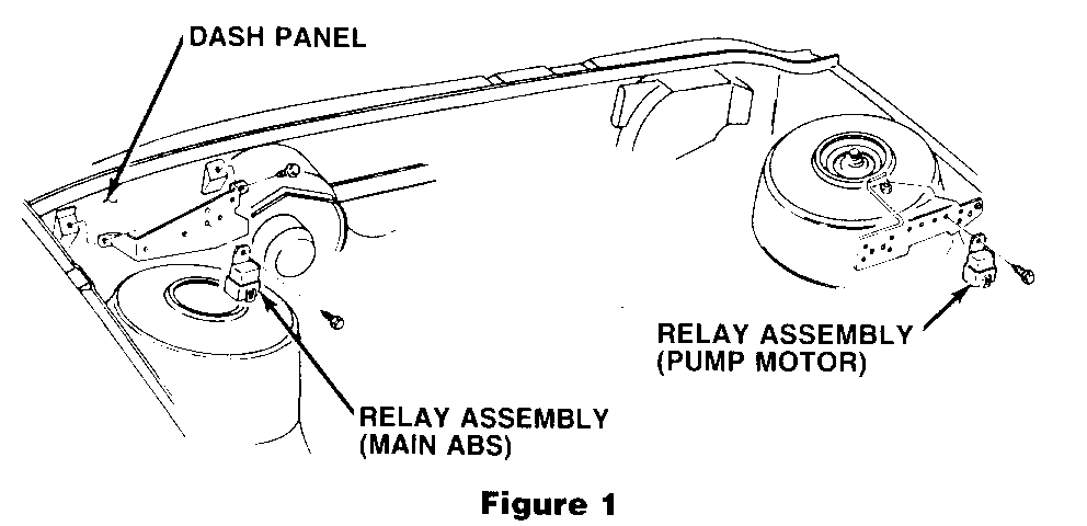
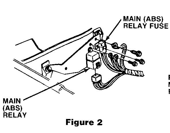
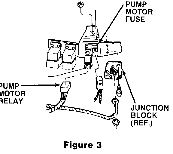
2. Remove two (2) relay assemblies (P/N 12040835) from their respective brackets (see figures 1, 2, & 3) and disconnect from electrical harness.
3. Reconnect electrical harness to new relay assemblies and install in original position. Torque bolts/screws to 3-4 N.m (27-35 lbs. in.)
RELAYS MUST BE INSTALLED WITH CONNECTOR AT BOTTOM TO PREVENT WATER ENTRY.
1986 MODEL YEAR VEHICLES ONLY
4. Replace both the pump motor 30 amp fuse and the ABS 30 amp main fuse (See figures 2 and 3).
CAUTION:
FAILURE TO FULLY DEPRESSURIZE THE HYDRAULIC ACCUMULATOR BEFORE PERFORMING SERVICE OPERATIONS COULD RESULT IN INJURY TO SERVICE PERSONNEL AND DAMAGE TO PAINTED SURFACES.
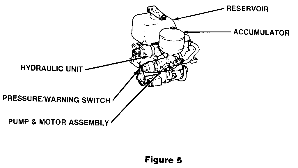
5. Visually inspect hydraulic pump and motor housing for any evidence of brake fluid seepage below pressure/warning switch. If any components require replacement, care should be taken to prevent brake fluid spillage onto motor (See figure 5).
A. If any evidence of brake fluid seepage is indicated, perform following steps as indicated in the 1987 Pontiac 6000 Service Manual pages 5E - 5, 6 & 7. If no seepage is indicated, proceed to step 5B.
1. Replace hydraulic pump and motor assembly.
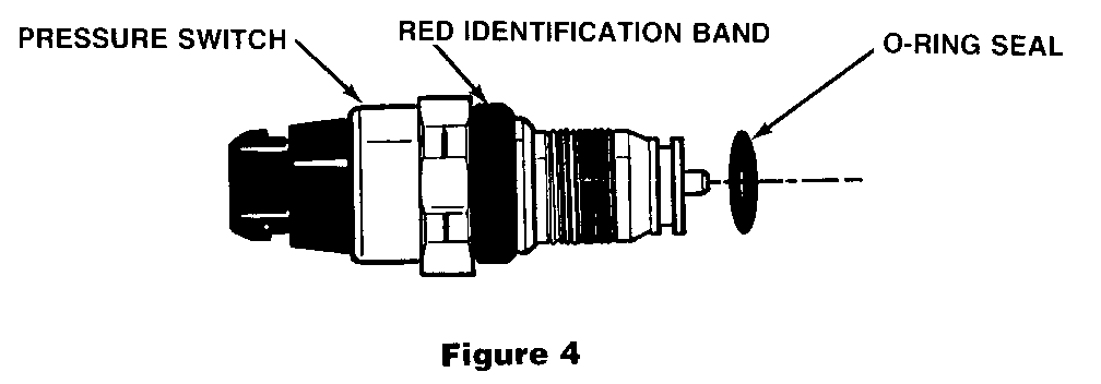
2. Inspect pressure/warning switch for red plastic identification band (See figure 4). If red bandis observed, switch requires replacement. If red band is not observed, original switch must be transferred to replacement pump and motor assembly.
B. If there is no evidence of brake fluid seepage, inspect only pressure/warning switch for red plastic identification band (See figure 4). If red band is observed, switch requires replacement. Follow pressure switch replacement procedure in 1987 Pontiac Service Manual page 5E - 7. If red band is not observed, proceed to step 5C.
C. If visual inspection does not indicate any parts replacement except for relay and fuses (as applicable) replaced in steps 2 - 3, reconnect battery cable and proceed to step 7.
6. If pressure/warning switch is replaced, without pump and motor assembly replacement; check fluid level in reservoir and ensure it is filled to mark. Do not overfill or underfill. Reconnect battery cable and turn ignition key to ON position until pump motor stops. Check for brake fluid leak.
NOTE: Use only DOT 3 brake fluid from a clean, sealed container. Do not use fluid from a container which is wet with water. Use of DOT 5 silicone fluid is not recommended. Internal damage to pump components may result.
If hydraulic pump motor assembly is replaced:
A. Fill reservoir with brake fluid. Connect battery cable.
B. Turn ignition key to ON position until pump motor stops.
C. Check for brake fluid leak.
D. Turn ignition key to OFF position and discharge accumulator. See Checking and Filling in 1987 Pontiac Service Manual page 5E - 3.
E. Ensure that brake fluid reservoir is filled to mark. Do not overfill or underfill.
INSTALLATION OF CAMPAIGN IDENTIFICATION LABEL
Clean surface of radiator upper mounting panel and apply a Campaign Identification Label. Make sure the correct campaign number is inserted on the label. This will indicate that the campaign has been completed.
Dear General Motors Customer:
This notice is sent to you in accordance with the requirements of the Canada Motor Vehicle Safety Act.
General Motors of Canada has determined that a defect which relates to motor vehicle safety may exist in some 1986-1987 Pontiac STE models, equipped with Anti-Lock Brake Systems (ABS).
Loss of the hydraulic pump motor after accumulator pressure has been depleted (approximately 10-30 normal stops), result in a total loss of rear brakes as well as power assist to the front brakes. The red "Brake" warning light would, before accumulated pressure has been depleted, illuminate and stay ON.
To correct these conditions, both the ABS and hydraulic pump motor relays and 30 amp fuses will be replaced. In addition, the hydraulic pump motor assembly and pressure/warning switch will be inspected and, if required, replaced. Instructions for making this correction have been sent to your Dealer. The labour time to complete this replacement ranges from 15-35 minutes depending on whether pump motor/pressure (waming) switch replacement is required. Please ask your Dealer if you wish to know how much additional time will be needed to process your vehicle.
This letter identifies your vehicle. Presentation of this letter to your Dealer will assist their Service personnel im completing the necessary correction to your vehicle in the shortest possible time.
Further assistance, if required, may be obtained from the General Motors Zone Office nearest you. Your vehicle Owner's Manual provides the location and phone number of each respective Zone Office.
General Motors bulletins are intended for use by professional technicians, not a "do-it-yourselfer". They are written to inform those technicians of conditions that may occur on some vehicles, or to provide information that could assist in the proper service of a vehicle. Properly trained technicians have the equipment, tools, safety instructions and know-how to do a job properly and safely. If a condition is described, do not assume that the bulletin applies to your vehicle, or that your vehicle will have that condition. See a General Motors dealer servicing your brand of General Motors vehicle for information on whether your vehicle may benefit from the information.
