A/C ODOR -CLEANING PROCEDURE & AFTERBLOW MODULE

MODELS AFFECTED: 1987 THROUGH 1990 CENTURY
Some of the above vehicles may experience odors emitted from the air conditioning system primarily at start up in hot, humid climates. This odor may be the result of debris in the heater/evaporator case and/or microbial growth on the evaporator core. To address this odor condition, the following equipment and procedure should be used.
REQUIRED EQUIPMENT
- GM Goodwrench air conditioning system disinfectant kit, P/N 25533404 - Kent-Moore tool J-36645 air conditioning system cleaning gun - Rubber gloves, safety goggles (ordinary safety glasses are not sufficient) - Pedestal fan - Afterblow module, P/N 25533406
Parts are currently available from GMSPO.
CAUTION:
THIS PROCEDURE SHOULD ONLY BE PERFORMED ON A COLD CAR. IT HAS BEEN DEMONSTRATED THAT IRRITATING VAPORS WILL BE FORMED IN THE ENGINE COMPARTMENT IF THE DISINFECTANT COMING OUT OF THE DRAIN OUTLET CONTACTS HOT ENGINE COMPONENTS.
SAFETY GLASSES MUST BE WORN, DISINFECTANT CAN CAUSE SUBSTANTIAL, BUT TEMPORARY EYE INJURY. DO NOT GET IN EYES OR ON CLOTHING. WASH THOROUGHLY WITH SOAP AND WATER AFTER HANDLING.
FIRST AID:
If disinfectant gets into eyes, hold eyelids open and flush with steady stream of water for 15 minutes. Obtain medical attention if irritation persists.
PROCEDURE:
1. Put on rubber gloves and safety goggles.
2. Pour the small bottle of the air conditioning system disinfectant kit, P/N 25533404 into the large bottle. Seal and invert the large container once or twice to mix the contents.
3. Connect battery charger to the battery and charge, during cleaning process, to avoid draining the battery.
4. Remove the resistor block as described in the Service Manual to access the evaporator core face closest to the blower. Do not disconnect the wiring connector.
CAUTION:
RESISTOR BLOCK MAY BE HOT
NOTICE:
Do not allow the coils of the resistor to be grounded to any metal surface as this may result in internal circuitry damage.
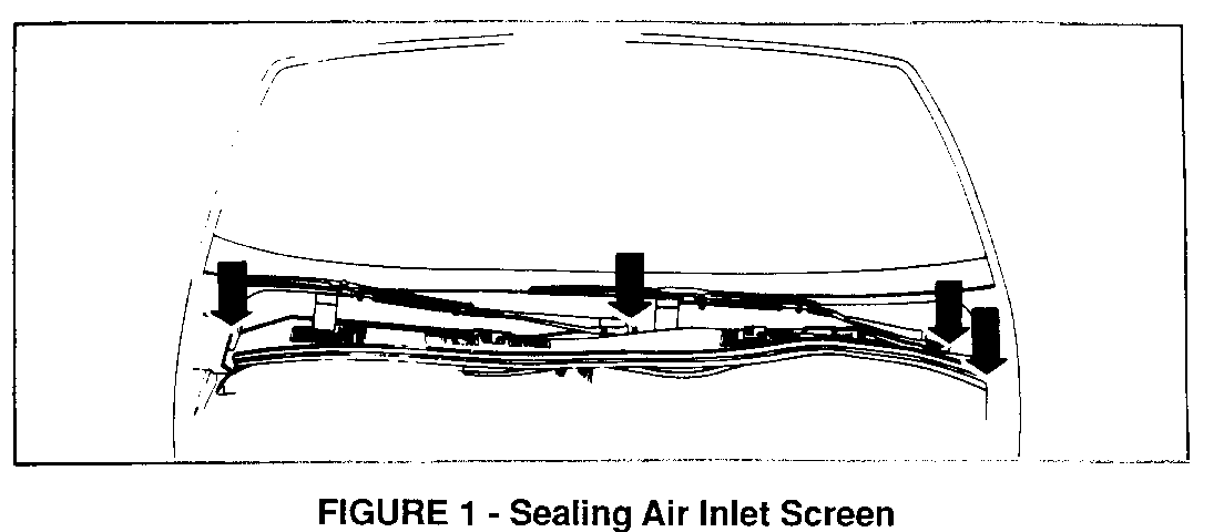
5. Check the heater/evaporator case for debris. Remove any debris present through the resistor block opening. If the debris is imbedded into the evaporator core face and cannot be removed, the core will have to be removed from the vehicle and cleaned off the car. If a large amount of debris is present in the heater/evaporator case, the air inlet screen will require sealing around the windshield wiper post holes and fender edges as shown in Figure 1.
6. Turn the ignition to the "On" position but do not start the vehicle.
7. Set the mode selector lever to vent, blower switch to low speed and temperature lever to full cold.
8. Open all windows and doors and exit the vehicle.
CAUTION:
DO NOT ENTER THE VEHICLE UNTIL CLEANING PROCEDURE IS COMPLETED TO AVOID EXPOSURE TO DISINFECTANT.
9. Place drain pan with at least a two quart capacity below the heater/evaporator drain to catch the disinfectant and rinse water runoff.
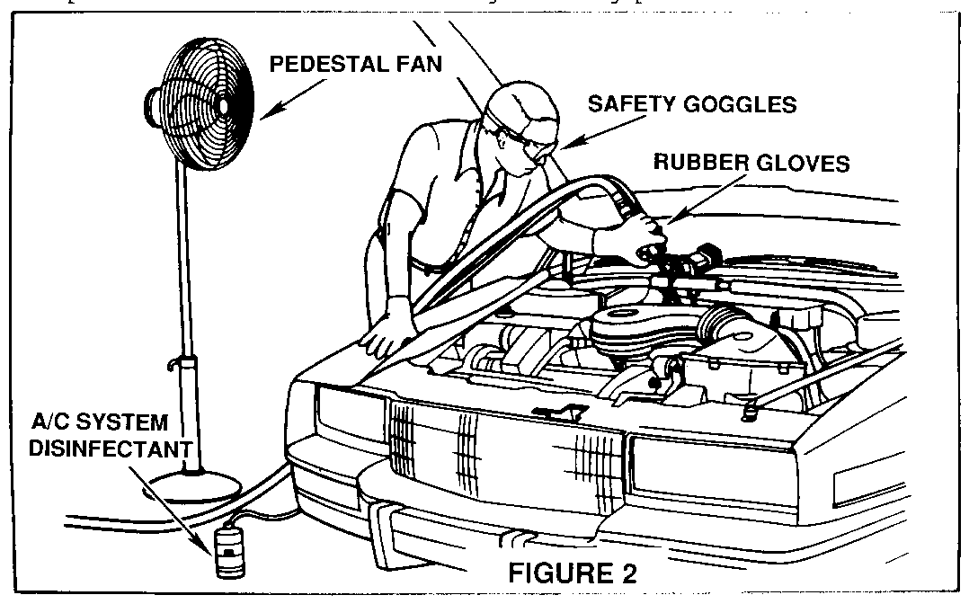
10. Position pedestal fan as shown in Figure 2 and turn on high to provide cross ventilation during cleaning procedure.
11. Use Kent-Moore tool J-36645 or equivalent siphon-type cleaning spray gun capable of delivering two ounces per minute of liquid when driven with shop air at 80-90 psi. Insert the nozzle of the spray gun through the resistor block opening and insert the siphon hose into the container of disinfectant. Take care to place the bottle of disinfectant in a secure upright position, to avoid spilling the contents. Direct the spray toward evaporator face, taking extra care to ensure adequate coverage of the corners and edges, completely saturating the entire core. Use the entire container of disinfectant.
12. Reach into the vehicle and turn the ignition to the off position and allow the evaporator core to soak for five (5) minutes.
13. Reach into the vehicle and start the engine.
14. Use the spray gun and one (1) quart of clean water to thoroughly rinse the evaporator core, to remove any and all of the disinfectant residue.
15. Reach into the vehicle and turn off the ignition and reinstall the resistor block.
CAUTION:
RESISTOR BLOCK MAY BE HOT
16. Dispose of disinfectant and rinse water in the drain pan into a sanitary drain system.
17. Disconnect the battery charger.
THE FOLLOWING STEPS ARE THE INSTRUCTIONS FOR THE INSTALLATION OF THE AFTERBLOW MODULE.
IMPORTANT:
The afterblow module will enable the blower to run at high speed for five (5) minutes approximately fifty (50) minutes after the vehicle ignition is turned off, if the compressor was engaged for four (4) minutes or more during the last ignition cycle.
IMPORTANT:
All The connections of the afterblow harness to the vehicle wiring should be spliced, using the proper techniques shown in Section 8A of the appropriate Service Manual. The splices should be made using splice clips, solder and wrapping the splice with electrical tape. Do not use instant connectors such as 3M's "SCOTCHLOK" brand.
IMPORTANT:
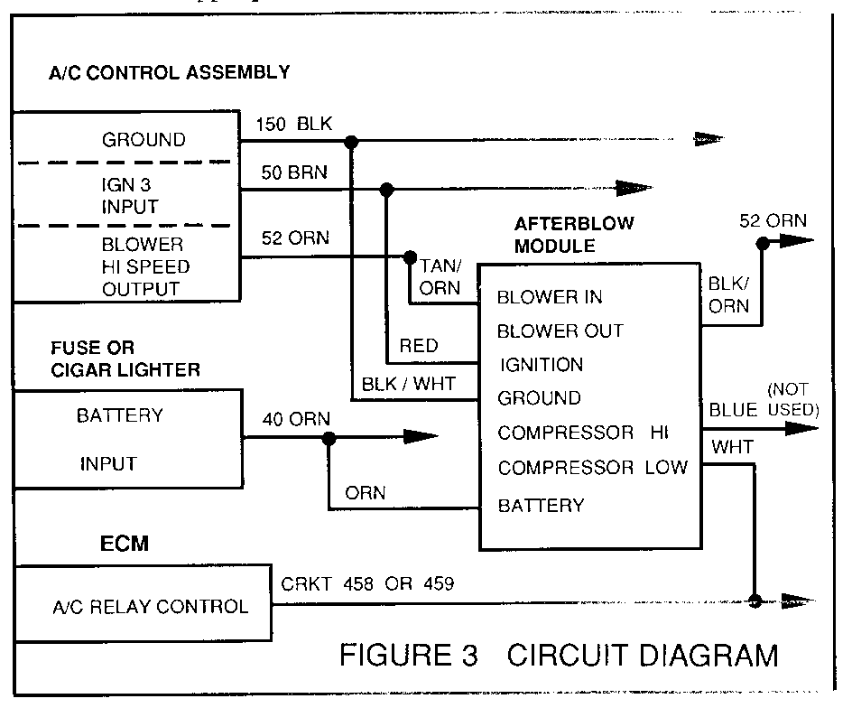
The circuit diagram shown in Figure 3 shows the circuit numbers generally used on the subject model year car lines. However, to make sure of the correct circuits and wire colors are spliced into, refer to Section 8A of the Service Manual.
18. Disconnect the negative battery cable.
19. Remove close out panels, fuse block, trim plates, A/C control head and glove box as required to gain access to the circuits shown in the circuit diagram. Refer to Section 8A of the Service Manual for component location and service procedures.
20. Disconnect the afterblow module from its jumper harness and set the module aside.
21. Splice the black/white wire (PIN C) of the harness into the black ground wire of the A/C control head wiring (circuit #150).
22. Splice the orange wire (PIN A) of the harness to a battery feed at the fuse block or the cigar lighter (circuit #40).
23. Splice the red wire (PIN B) of the harness to the ignition feed wire of A/C control head wiring (circuit #50).
24. Cut the orange high speed blower output wire (circuit #52) of the A/C control wiring. Splice the tan/orange wire (PIN F) of the harness to the orange wire leading to the A/C control head. Splice the black/orange wire (PIN G) of the harness to the other end of the orange wire leading to the blower motor.
25. Splice the white wire (PIN E) of the harness to the A/C compressor control wire coming out of the ECM. This is usually circuit #458, #459 or #366.
26. Cut off the bare end of the blue wire (PIN D) of the harness, tape the end and fold and tape the wire to the harness.
27. Connect the negative battery cable.
28. Test the afterblow module for operation.
29. Mount the afterblow module in a convenient location under the dash, using foam insulation as necessary to ensure a rattle-free installation of the module.
30. Replace the vehicle components that were removed for the installation of the module.
TO TEST THE AFTERBLOW MODULE USE THE FOLLOWING PROCEDURE:
1. Start the engine.
2. Turn the A/C system on to engage the compressor.
3. Connect jumper wire to apply battery voltage to the open cavity (PIN H) (green wire) of the afterblow module for at least thirty (30) seconds with compressor engaged.
4. Turn the ignition key off.
5. The blower should come on after approximately ten (10) seconds) for one (1) second then go off.
6. Disconnect the jumper wire.
NOTICE:
The afterblow module is not compatible with some non-factory installed theft alarm systems. The module current draw at key off position could trigger alarms that sense battery voltage changes or current drain.
7. Advise owner of changes in operation of blower motor, (will enable the blower motor to run at high speed for (5) minutes approximately fifty (50) minutes after the vehicle ignition is turned off, if the compressor was engaged for four (4) minutes or more during the last ignition cycle).
WARRANTY INFORMATION:
Labor Operation No.: T6235 Labor Time: 1.9 hrs.
If the debris needs to be removed from the heater/evaporator case and the air inlet screen needs to be sealed, use and add time of .2 hours.


General Motors bulletins are intended for use by professional technicians, not a "do-it-yourselfer". They are written to inform those technicians of conditions that may occur on some vehicles, or to provide information that could assist in the proper service of a vehicle. Properly trained technicians have the equipment, tools, safety instructions and know-how to do a job properly and safely. If a condition is described, do not assume that the bulletin applies to your vehicle, or that your vehicle will have that condition. See a General Motors dealer servicing your brand of General Motors vehicle for information on whether your vehicle may benefit from the information.
