SERVICE MANUAL UPDATE ENGINE CRANK BUT WON'T RUN

SUBJECT: REVISED FACING PAGE AND CHART
MODELS AFFECTED: 1987-89 CENTURYS WITH 2.5L ENGINE (VIN CODE R) 1987-89 SKYLARKS WITH 2.5L ENGINES (VIN CODE U) 1987 SOMERSETS WITH 2.5L ENGINES (VIN CODE U)
NOTICE: This bulletin supersedes all information contained in previously released bulletin 89-6-1, which should be discarded.
This bulletin revises Chart A-3 (Page 2 of 3), "Engine Cranks But Won't Run", used in the diagnosis of 1987 through 1989 "N" carline (VIN U) and "A" carline (VIN R) with 2.04925L engines.
When measuring crankshaft sensor resistance, as described in "Test Description" Step Number 5, make certain the crankshaft sensor is at room temperature. High resistance readings could result if the crankshaft sensor is warmer than room temperature.
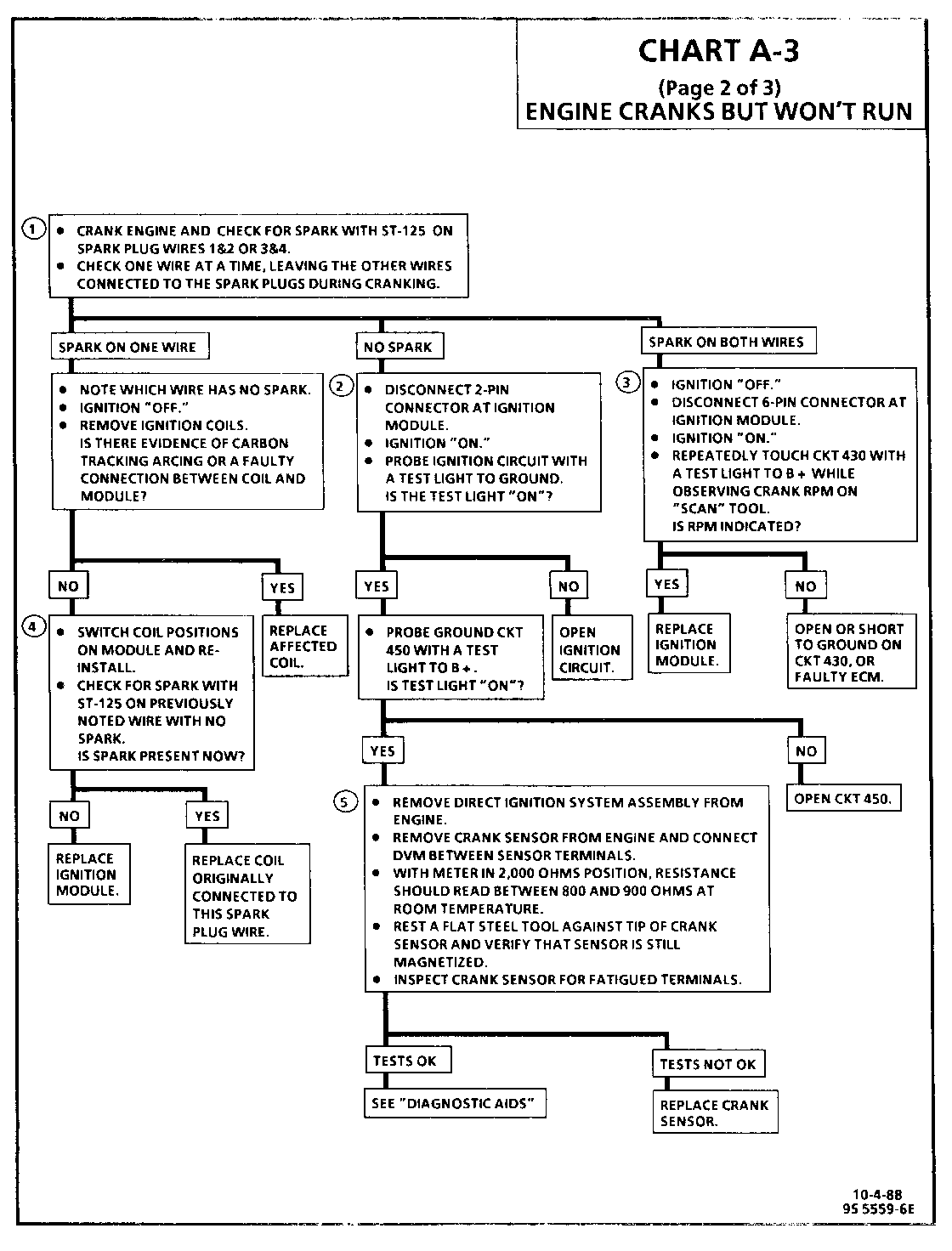
Also, a "Diagnostic Aids" section has been added to the facing page which addresses the correction procedure for an intermittent crankshaft sensor condition. The diagnostic chart has been updated to reflect this change as well. CHART A-3 (Page 2 of 3) ENGINE CRANKS BUT WON'T RUN
Circuit Description:
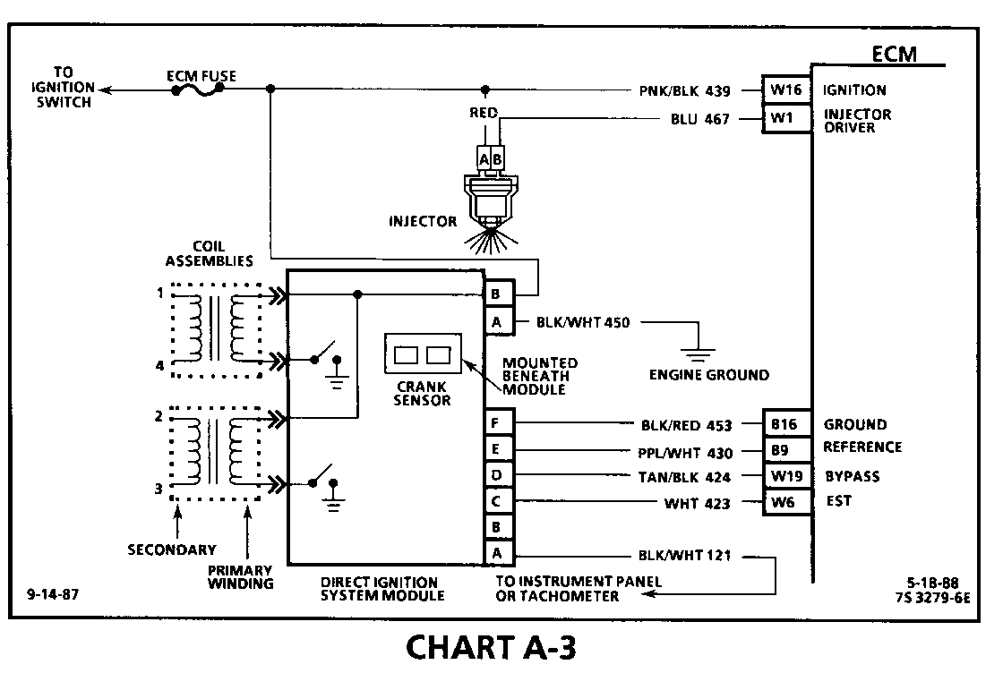
A magnetic crank sensor is used to determine engine crankshaft position, much the same way as the pick-up coil did in HEI type systems. The sensor is mounted in the block, near a slotted wheel on the crankshaft. The rotation of the wheel creates a flux change in the sensor, which produces a voltage signal. The DIS ignition module processes this signal and creates the reference pulses needed by the ECM to trigger the correct coil at the correct time.
If the "Scan" tool did not indicate cranking rpm, and there is no spark present at the plugs, the problem lies in the direct ignition system or the power and ground supplies to the module.
Test Description: Numbers below refer to circled numbers on the diagnostic chart.
1. The direct ignition system uses two plugs and wires to complete the circuit of each coil. The other spark plug wire in the circuit must be left connected to create a spark.
2. This test will determine if the 12 volt supply and a good ground is available at the DIS ignition module.
3. This test will determine if the ignition module is not generating the reference pulse, or if the wiring or ECM are at fault. By touching and removing a test light to 12 volts on CKT 430, a reference pulse should be generated. If rpm is indicated, the ECM and wiring are OK.
4. This test will determine if the ignition module is triggering the problem coil, or if the tested coil is at fault. This test could also be performed by substituting a known good coil. The secondary coil winding can be checked with a DVM. There should be 5,000 to 10,000 ohms across the coil towers. There should not be any continuity from either coil tower to ground.
5. Checks for continuity of the crank sensor and connection as well as sensor magnetism. These checks must be performed with the crank sensor at room temperature in order to obtain accurate readings.
DIAGNOSTIC AIDS:
An intermittent problem with crankshaft sensor could cause a "Cranks But Won't Run condition. Therefore, the crankshaft sensor must be replaced first. If the "Cranks But Won't Run" condition persists, then replace the DIS module.


General Motors bulletins are intended for use by professional technicians, not a "do-it-yourselfer". They are written to inform those technicians of conditions that may occur on some vehicles, or to provide information that could assist in the proper service of a vehicle. Properly trained technicians have the equipment, tools, safety instructions and know-how to do a job properly and safely. If a condition is described, do not assume that the bulletin applies to your vehicle, or that your vehicle will have that condition. See a General Motors dealer servicing your brand of General Motors vehicle for information on whether your vehicle may benefit from the information.
