SERVICE MANUAL UPDATE SEC. 7A TRANSAXLE ASSEMBLY

SUBJECT: SERVICE MANUAL UPDATE - SECTION 7A - 4T60 TRANSAXLE ASSEMBLY REPLACEMENT (REVISED PROCEDURE)
MODELS AFFECTED: 1989-'91 CENTURY WITH 3300 V6 AND 4T60 TRANSAXLE
SERVICE MANUAL UPDATE - SECTION 7A
The following Transaxle Assembly Replacement Procedure updates and replaces the current procedure found in the 1989-91 Century Service Manual Section 7A.
4T60 TRANSAXLE ASSEMBLY
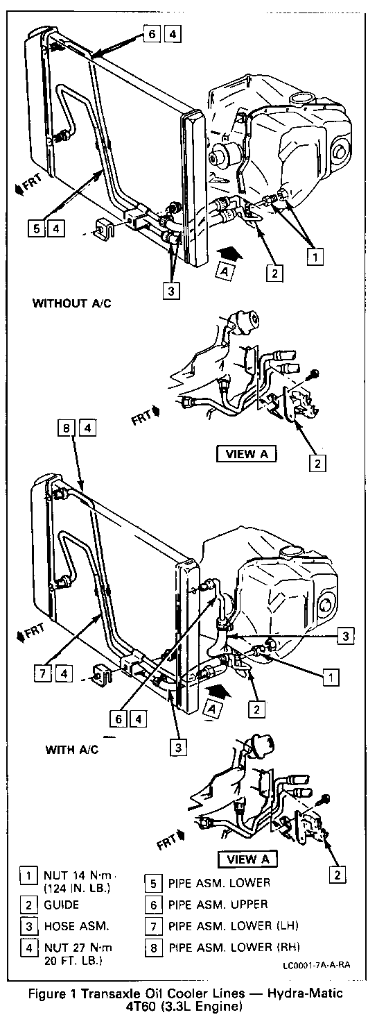
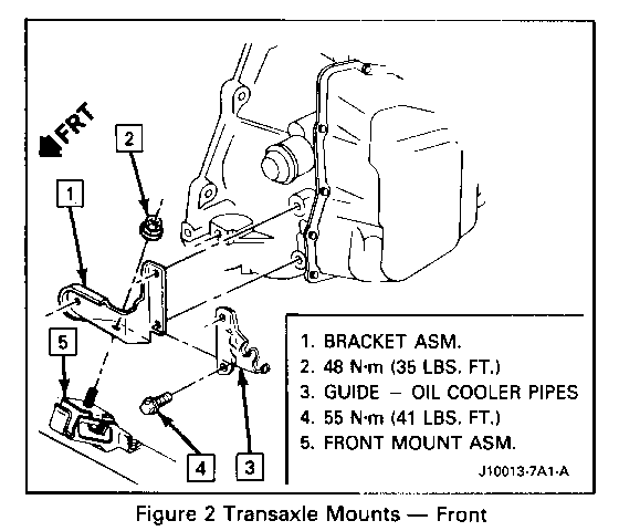
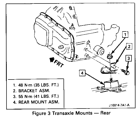
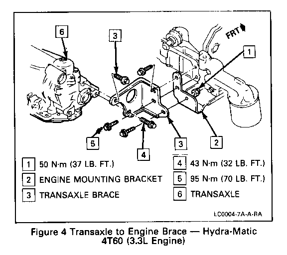
Figures 1 through 7
Tools Required:
J 28467-A Engine Support Fixture J 34754 Drive Axle Seal Protector J 35944 Oil Cooler and Line Flusher J 37292-A Axle Seal Protector
Remove or Disconnect
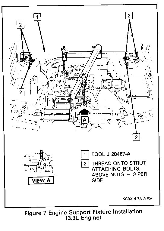
1. Negative battery cable 2. Air cleaner and duct assembly 3. T.C.C. switch electrical connector 4. A/C low pressure switch electrical connector 5. Neutral start switch electrical connector 6. T.V. cable from throttle body and transaxle 7. Shift control cable from transaxle mounting bracket and lever 3. Vacuum modulator line from modulator 9. Three upper transaxle bolts from engine and ground wires 10. Steering shaft pinch bolt. Refer to Power Steering Gear and Pump (Section 3B1). 11. Install J 28467-A 12. Raise vehicle and suitably support. Refer to General Information (Section 0A). 13. Front tire and wheel assemblies. Refer to Tires and Wheels (Section 3E). 14. Engine splash shields 15. Pinch bolts from control arms. Refer to Front Suspension (Section 3C). 16. Stabilizer shaft bolts and reinforcement plates from frame 17. Stabilizer shaft nuts and bracket from control arm. Separate stabilizer shaft from control arm. 18. Using a 7/16 inch drill bit, drill through two spot welds located between front and rear holes of left front stabilizer shaft mounting. 19. Front and rear transaxle mounting nuts 20. Power steering cooler line bolts 21. Right frame to left frame retaining bolt. Position jack stand under frame for support. Refer to Frame and Underbody (Section 10-3). 22. Loosen two right frame mounts and discard bolts. 23. Two left frame bolts from frame 24. Left frame assembly 25. Transaxle mount retaining bolts from transaxle case. Remove mount. 26. Two flywheel inspection covers 27. Torque converter bolts
NOTICE: DRIVE AXLE SEAL PROTECTOR J 34754 SHOULD BE MODIFIED AND INSTALLED ON ANY DRIVE AXLE PRIOR TO SERVICE PROCEDURES ON OR NEAR THE DRIVE AXLE. FAILURE TO OBSERVE THIS MAY RESULT IN SEAL DAMAGE AND POSSIBLE JOINT FAILURE. REFER TO DRIVE AXLE (SECTION 4D) FOR INFORMATION ON J 34754 AND FOR PROPER DRIVE AXLE REMOVAL AND HANDLING PROCEDURES.
28. Drive axles from transaxle. Refer to Drive Axle (Section 4D). 29. Transaxle support bracket bolts from transaxle 30. Vehicle speed sensor electrical connector from transaxle 31. Transaxle cooler lines 32. Install transaxle jack 33. Rear transaxle bolts from engine 34. Remaining transaxle bolts 35. Transaxle
Inspect
For inspection and overhaul procedures, refer to Unit Repair Section of the Service Manual.
Clean
Transaxle oil cooler and lines should be flushed with J 35944 or equivalent whenever the transaxle has been removed for overhaul or replacement of the torque converter pump or case. Refer to "Oil Cooler Flushing" in the Service Manual.
Install or Connect
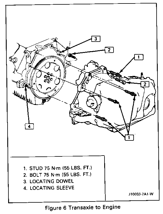
1. Transaxle 2. Remaining transaxle bolt
Tighten Bolts to 75 N.m (55 lbs. ft.)
3. Remove transaxle jack 4. Transaxle cooler lines 5. Rear transaxle to engine bolt
Tighten Bolts to 55 N.m (41 lbs. ft.)
6. V.S.S. electrical connector to transaxle 7. Transaxle support bracket and bolts to transaxle
Tighten Bolts to 43 N.m (32 lbs. ft.)
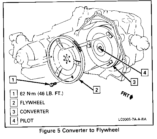
8. Drive axles to transaxle. Refer to Drive Axle (Section 4D). 9. Converter to flywheel bolts
Tighten All bolts to 62 N.m (46 lbs. ft.) Retorque the first bolt after all three have been tightened.
10. Two flywheel inspection covers
Tighten Bolts to 10 N.m (89 lbs. in.)
11. Transaxle mount and transaxle mounting bolts to transaxle case.
Tighten Bolts to 55 N.m (41 lbs. ft.)
12. Left frame assembly 13. Left frame assembly bolts to body
Tighten Bolts to 54 N.m (40 lbs. ft.)
14. Right frame bolts to body
Tighten Bolts to 54 N.m (40 lbs. ft.)
15. Remove jack stand 16. Right frame to left frame retaining bolts. Refer to Frame and Underbody (Section 10-3). 17. Power steering cooler lines 18. Transaxle mounting nuts
Tighten Nuts to 50 N. m (37 lbs. ft.)
19. Left stabilizer shaft to control arm nuts 20. Stabilizer shaft bolts and reinforcement plates to frame using support. 21. Pinch bolts to control arms. Refer to Front Suspension (Section 3C). 22. Engine 3plash shields 23. Front tire and wheel assemblies. Refer to Tires and Wheels (Section 3E). 24. Lower vehicle and remove J 24867-A. 25. Steering shaft pinch bolt. Refer to Power Steering Gear and Pumps (Section 3Bl). 26. Three upper transaxle bolts and ground wires to engine.
Tighten Bolts 75 N.m (55 lbs. ft.)
27. Vacuum modulator line to modulator 28. Transaxle shift cable, mounting bracket and lever 29. T.V. cable to throttle body and transaxle 30. T.C.C. switch electrical connector 31. A/C low pressure switch electrical connector 32. Neutral start switch electrical connector 33. Air cleaner and duct assembly 34. Negative battery cable
Adjust
T.V. cable. Refer to "T. V. Cable Setting" in this section. Toe-in, if required. Refer to Wheel Alignment (Section 3A).
Transaxle fluid
Inspect Proper fluid levels Fluid leaks
General Motors bulletins are intended for use by professional technicians, not a "do-it-yourselfer". They are written to inform those technicians of conditions that may occur on some vehicles, or to provide information that could assist in the proper service of a vehicle. Properly trained technicians have the equipment, tools, safety instructions and know-how to do a job properly and safely. If a condition is described, do not assume that the bulletin applies to your vehicle, or that your vehicle will have that condition. See a General Motors dealer servicing your brand of General Motors vehicle for information on whether your vehicle may benefit from the information.
