INADEQUATE A/C PERFORMANCE INSTALL CONDENSER/FAN & MEMCAL

SUBJECT: INADEQUATE AIR CONDITION SYSTEM PERFORMANCE (INSTALL CONDENSER, PUSHER FAN, MEMCAL)
VEHICLES AFFECTED: 1989-91 "A" CAR WITH 3.3L (LG7 V6) ENGINE
CONDITION:
---------- Some customers may comment on inadequate A/C performance.
CAUSE:
------ A/C compressor shutoff at idle designed to provide engine idle smoothness and prevent the engine from stalling. Also, an A/C condenser air recirculation condition that can reduce the A/C system capacity at high ambient temperatures and relative humidity.
CORRECTION:
----------- Install a new condenser, pusher fan and new ECM Memory Calibrator (MEMCAL), using the following service parts and procedure:
SERVICE PARTS
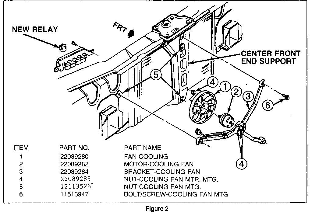
QTY PART NUMBER PART NAME --- ----------- --------------------------- 1 22089280 Fan-Aux. Engine Cooling 1 22089282 Motor-Aux. Engine Cooling Fan 1 22089284 Bracket-Aux. Engine Cooling Fan 4 22089285 Nut-Aux. Engine Cooling Fan 3 11513947 Bolt/Screw-Engine Cooling Fan Bracket 1 12113526 Harness Asm-Aux. Engine Cooling Fan 1 11509135 Bolt/Screw-Wiring Harness Ground 1 52461314 Condenser Asm.-Air Condition 2 14077377 Insulator-A/C Condenser Lower 2 14077378 Insulator-A/C Condenser Upper 4 411700 Retainer-Plastic Push-In 4 12337820 Retainer-Plastic Adjustable 1 10188092 Label-A/C Charge Specification
Also, one of the following ECM Memory Calibrators (MEMCAL) for the appropriate application:
PART BROADCAST SCANNER APPLICATION NUMBER CODE ID ------- ----------- -------- ------------------ 16168738 AZBW 8764 1989 Nationwide W/C60 and MD9 16168740 AZBX 8774 1989 Nationwide W/C60 and ME9 16168735 AZBS 8734 1990-91 Federal W/C60 and MD9 16168745 AZBZ 8794 1990-91 Calif. W/C60 and MD9 16168736 AZBT 8744 1990-91 Federal W/C60 and ME9 16168742 AZBY 8784 1990-91 Calif. W/C60 and ME9
C60 is A/C, MD9 is 3sp Auto Trans and ME9 is Auto 4sp Trans.
PROCEDURE:
---------- Where necessary use the specified torque requirements as shown in the appropriate Service Manual.
1. Disconnect the negative battery cable.
2. Discharge and recover the A/C system.
3. Remove the grille.
4. Remove the A/C condenser and the centre front end support following the appropriate Service Manual procedures.
5. On Oldsmobile only, remove the side air baffles from the old condenser.
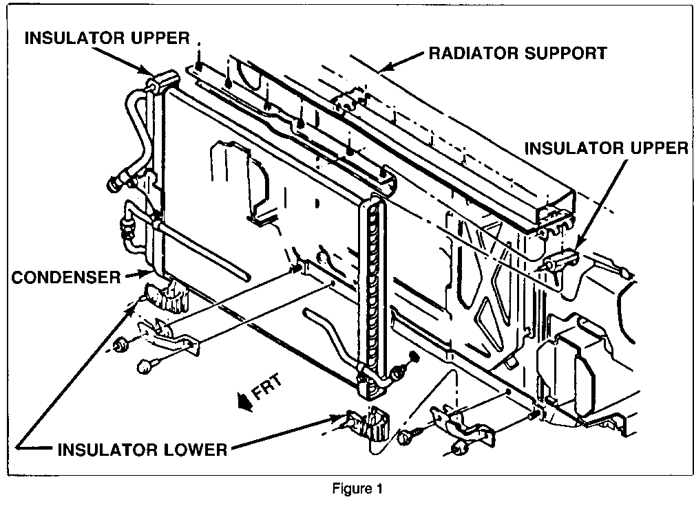
6. Discard the old upper and lower condenser insulators, refer to Figure 1.
7. On Oldsmobile only, install the side air baffles to the new condenser, using the new plastic push in retainers. Leave out one of the RH baffle retainers until the fan harness is routed. Slit the baffles as necessary to fit around the new condenser pipes.
8. Install the new condenser, as shown in Figure 1, using Service Manual procedures. Tie the outboard side of the baffles, on Oldsmobile, to the Energy Absorbing Units using two of the adjustable plastic retainers.
9. Install the front end center support.
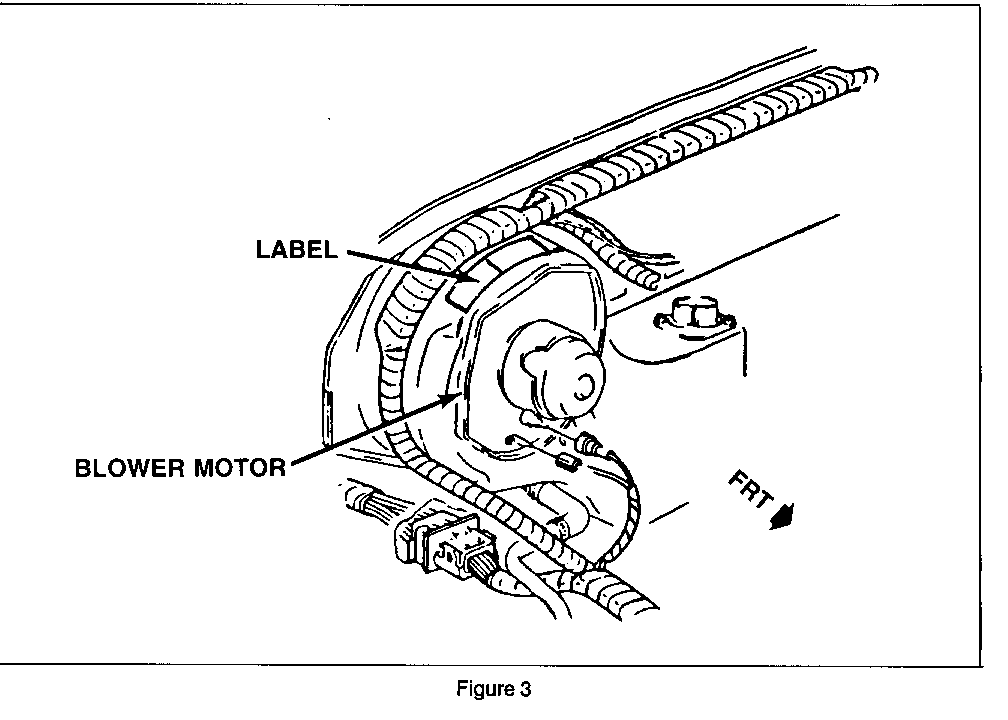
10. Clean the top surface of the blower motor and install the new A/C charge specification Label. Figure 2.
11. Evacuate, charge and leak test the A/C system. Charge the system to 1.02 Kg (2.25 lbs.)
12. Assemble the cooling fan to the motor and fan and motor assembly to the bracket, as shown in Figure 3.
13. Install the cooling fan assembly, as shown in Figure 3.
14. Route the motor harness along the RH outboard leg of the bracket and secure in place with the two other adjustable plastic retainers. Cut off excess ends of retainer.
15. Attach the jumper wiring harness to the fan motor harness and route jumper harness through the front end panel.
16. Install the remaining plastic push-in retainer to the RH side air baffle and condenser.
17. Install the new relay (part of jumper wiring harness) in the relay mounting bracket on the RH side of front end panel, as shown in Figure 3.
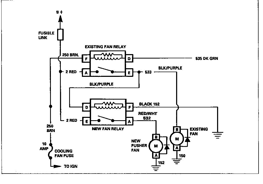
18. Splice the red wire from cavity E of the new relay connector to the red wire in cavity A of the existing cooling fan relay connector. Cover the splice with the heat shrink tubing that is taped to the wire. Figure 4.
19. Splice the black/purple wire from cavity D of the new relay connector to the black/purple wire of cavity E of the existing cooling fan relay connector and cover the splice with heat shrink tubing.
Important: Use the approved splicing materials and instructions as shown in the appropriate Service Manual.
20. To ground the new relay and fan motor, install the black wire ring terminal of the wiring harness to the relay mounting bracket by replacing one of the mounting screws with screw, P/N 11509135.
21. Install the grille.
22. Replace the existing ECM Memory Calibrator (MEMCAL) with the new appropriate Calibrator, using the procedures specified in the Service Manual.
23. Connect the negative battery cable.
24. Check for proper operation of the new pusher type cooling fan.
For vehicle being repaired under warranty use:
Labour Time: 2.8 Hours


General Motors bulletins are intended for use by professional technicians, not a "do-it-yourselfer". They are written to inform those technicians of conditions that may occur on some vehicles, or to provide information that could assist in the proper service of a vehicle. Properly trained technicians have the equipment, tools, safety instructions and know-how to do a job properly and safely. If a condition is described, do not assume that the bulletin applies to your vehicle, or that your vehicle will have that condition. See a General Motors dealer servicing your brand of General Motors vehicle for information on whether your vehicle may benefit from the information.
