SERVICE MANUAL UPDATE SEC. 6A ENGINE MECHANICAL-FLYWHEEL

SUBJECT: MANUAL UPDATE SECTION 6A - ENGINE MECHANICAL FLYWHEEL REPLACEMENT REVISED PROCEDURE
VEHICLES AFFECTED: 1989-91 OLDS AND BUICK A-CAR W/3.3,4T60
The following Flywheel Replacement procedure updates and replaces the current procedure found in the 1989 through 1991 Oldsmobile Cutlass Ciera, Cutlass Cruiser and Buick Century Service Manual - Section 6A.
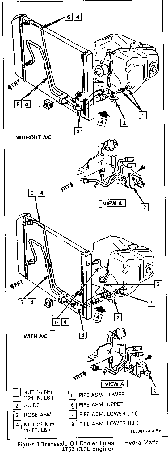
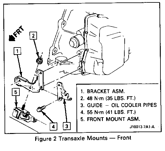
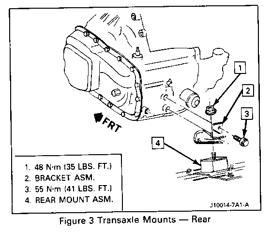
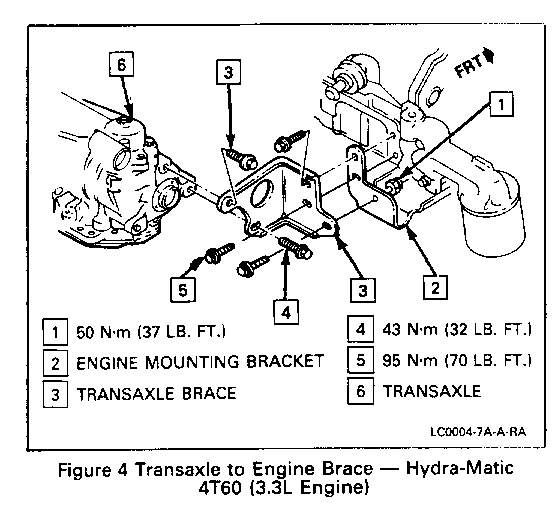
FLYWHEEL REPLACEMENT - Figures 1 through 7
Tools Required:
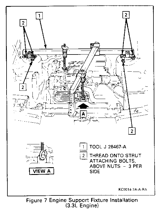
J 28467-A Engine Support FIXTURE J 34754 Drive Axle Seal Protector J 35944 Oil Cooler and Line Flusher J 37292-A Axle Seal Protector
Remove or disconnect
1. Negative battery cable. 2. Air cleaner and duct assembly. 3. T.C.C. switch electrical connector. 4. A/C low pressure switch electrical connector. 5. Neutral start switch electrical connector. 6. T.V. cable from throttle body and transaxle. 7. Shift control cable from transaxle mounting bracket and lever. 8. Vacuum modulator line from modulator. 9. Three upper transaxle bolts from engine and ground wires. 10. Steering shaft pinch bolt. Refer to Power Steering Gear and Pump (Section 3B1) . 11. Install J 28467-A. 12. Raise vehicle and suitably support. Refer to General Information (Section 0A). 13. Front tire and wheel assemblies. Refer to Tires and Wheels (Section 3E). 14. Engine splash shields. 15. Pinch bolts from control arms. Refer to Front Suspension (Section 3C). 16. Stabilizer shaft bolts and reinforcement plates from frame. 17. Stabilizer shaft nuts and bracket from control arm. Separate stabilizer shaft from control arm. 18. Using a 7/16 inch drill bit, drill through two spot welds located between front and rear holes of left front stabilizer shaft mounting. 19. Front and rear transaxle mounting nuts. 20. Power steering cooler line bolts. 21. Right frame to left frame retaining bolt. Position jack stand under frame for support. Refer to Frame and Underbody (Section 10-3) 22. Loosen two right frame mounts and discard bolts. 23. Two left frame bolts from frame. 24. Left frame assembly. 25. Transaxle mount retaining bolts from transaxle case. Remove mount. 26. Two flywheel inspection covers. 27. Torque converter bolts.
NOTICE: DRIVE AXLE SEAL PROTECTOR i 34754 SHOULD BE MODIFIED AND INSTALLED ON ANY DRIVE AXLE PRIOR TO SERVICE PROCEDURES ON OR NEAR THE DRIVE AXLE. FAILURE TO OBSERVE THIS MAY RESULT IN SEAL DAMAGE AND POSSIBLE JOINT FAILURE. REFER TO DRIVE AXLE (SECTION 4D) FOR INFORMATION ON i 34754 AND FOR PROPER DRIVE AXLE REMOVAL AND HANDLING PROCEDURES.
28. Drive axles from transaxle. Refer to Drive Axle (Section 4D). 29. Transaxle support bracket bolts from transaxle. 30. Vehicle speed sensor electrical connector from transaxle. 31. Transaxle cooler lines. 32. Install transaxle jack. 33. Rear transaxle bolts from engine. 34. Remaining transaxle bolts. 35. Transaxle. 36. Flywheel attaching bolts and flywheel. Discard bolts.
Inspect
Flywheel, if cracked, badly worn or broken teeth, replace. Crankshaft and flywheel mating surfaces for burrs. Remove as required.
Install or Connect
1. Flywheel and six new attaching bolts. Apply thread lock compound GM P/N 12345493 or equivalent to bolt threads before assembly.
Tighten Bolts to 82 N.m (61 ft.lbs.)
2. Dial indicator on engine block and check flywheel runout at three attaching bosses.
IMPORTANT
The crankshaft end-play must be held in one direction during this check. Run-out should not exceed 0.381 mm (0.015 in.).
3. If run-out exceeds 0.381 mm (0.015 in.) attempt to correct by tapping high side with mallet. 4. If condition cannot be corrected, replace flywheel. 5. Transaxle. 6 Remaining transaxle bolt.
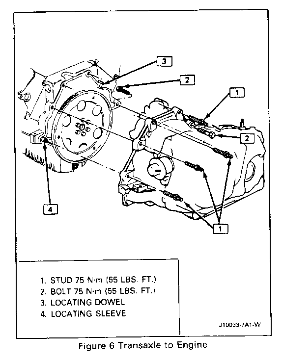
Tighten Bolts to 75 N.m (55 ft.lbs.)
7. Remove transaxle jack. 8. Transaxle cooler lines.
9. Rear transaxle to engine bolt.
Tighten Bolts to 55 N.m (41 ft.lbs.).
10. V.S.S. electrical connector to transaxle. 11. Transaxle support bracket and bolts to transaxle.
Tighten Bolts to 43 N.m (32 ft.lbs.)
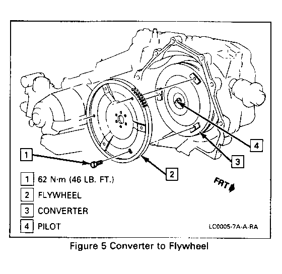
12. Drive axles to transaxle. Refer to Drive Axle (Section 4D). 13. Converter to flywheel bolts.
Tighten All bolts to 62 N.m (46 ft. lbs.). Retorque the first bolt after all three have been tightened.
14. Two flywheel inspection covers.
Tighten Bolts to 10 N.m (89 ft.lbs.)
15. Transaxle mount and transaxle mounting bolts to transaxle case.
Tighten Bolts to 55 N.m (41 ft.lbs.).
16. Left frame assembly. 17. Left frame assembly bolts to body.
Tighten Bolts to 54 N.m (40 ft.lbs.)
18. Right frame bolts to body.
Tighten Bolts to 54 N.m (40 ft.lbs.).
19. Remove jack stand. 20. Right frame to left frame retaining bolts. Refer to Frame and Underbody (Section 10-3). 21. Power steering cooler lines. 22. Transaxle mounting nuts.
Tighten Nuts to 50 N.m (37 ft.lbs.).
23. Left stabilizer shaft to control arm nuts. 24. Stabilizer shaft bolts and reinforcement plates to frame using a jack stand for support. 25. Pinch bolt to control arms. Refer to Front Suspension (Section 3C). 26. Engine splash shields. 27. Front tire and wheel assemblies. Refer to Tires and Wheels (Section 3E). 28. Lower vehicle and remove i 24867-A. 29. Steering shaft pinch bolt. Refer to Power Steering Gear and Pumps (Section 3B1) . 30. Three upper transaxle bolts and ground wires to engine.
Tighten Bolts to 75 N.m (55 ft.lbs.).
31. Vacuum modulator line to modulator. 32. Transaxle shift cable, mounting bracket and lever. 33. T.V. cable to throttle body and transaxle. 34. T.C.C. switch electrical connector. 35. A/C low pressure switch electrical connector. 36. Neutral start switch electrical connector. 37. Air cleaner and duct assembly. 38. Negative battery cable.
Adjust T.V. cable. Refer to "T.V. Cable Setting" in the Service Manual Toe-in, if required. Refer to Wheel Alignment (Section 3A). Transaxle fluid.
Inspect Proper fluid levels. Fluid leaks.
General Motors bulletins are intended for use by professional technicians, not a "do-it-yourselfer". They are written to inform those technicians of conditions that may occur on some vehicles, or to provide information that could assist in the proper service of a vehicle. Properly trained technicians have the equipment, tools, safety instructions and know-how to do a job properly and safely. If a condition is described, do not assume that the bulletin applies to your vehicle, or that your vehicle will have that condition. See a General Motors dealer servicing your brand of General Motors vehicle for information on whether your vehicle may benefit from the information.
