
| Subject: | Revised Piston Pin Removal/Installation Procedures |
| Models: | 1994-96 Buick Regal |
| 1994-96 Chevrolet Beretta, Corsica |
| 1995-99 Chevrolet Monte Carlo |
| 1994-96 Oldsmobile Cutlass Cierra |
| 1994-97 Oldsmobile Cutlass Supreme |
| 1994-98 Oldsmobile Achieva |
| 1997-99 Oldsmobile Cutlass |
| 1994-99 Pontiac Grand Prix |
| with 3.1L Engine (VIN M -- RPO L82) |
This bulletin is being revised to update the models information. Please
discard Corporate Number 01-06-01-002 (Section 06-Engines).
This bulletin is being issued to revise the piston and rod assembly
removal/installation procedures in the Engine Section of the Service Manual.
Revised Service Procedure
The following steps are provided to assist in the replacement of the
piston assemblies.
Tools Required
| • | J 24086 Connecting Rod Press |
| • | J 24086-C Piston Pin Remover/Installer |
| • | Connecting Rod Oven (Rod Kiln) |
Piston and Connecting Rod Disassemble
Important: Prior to piston/connecting rod removal, mark or identify the piston/connecting
rod assembly, and its orientation to the front of the engine, before removal.
- Remove the pistons from the engine following the instructions found
in the Engine Repair Section of the Service Manual.
Notice: A rod kiln MUST be used during assembly of the connecting rod to the
piston. If a connecting rod kiln is not available, seek the assistance of
a reputable machine shop with a kiln. Under NO circumstances should an acetylene
torch or other uncontrolled heating device be used on connecting rods, as
permanent damage to the connecting rod may result.
Important: It is not necessary to replace the piston rings, unless they were damaged
during the repair process. If the piston rings are to be reused, mark or
identify the location/order of the rings as they correspond to location on
the piston being serviced. Refer to ring gap placement instructions found
in the Engine Repair Section of the Service Manual.
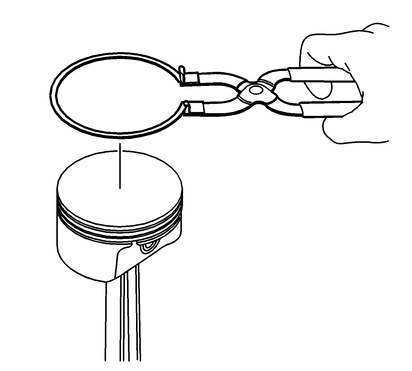
- Using piston ring pliers, remove the piston rings from the piston.
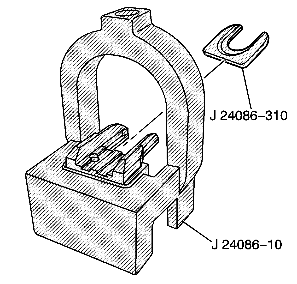
- Install the J 24086-310 fork insert
into the J 24086-10 fixture support assembly.
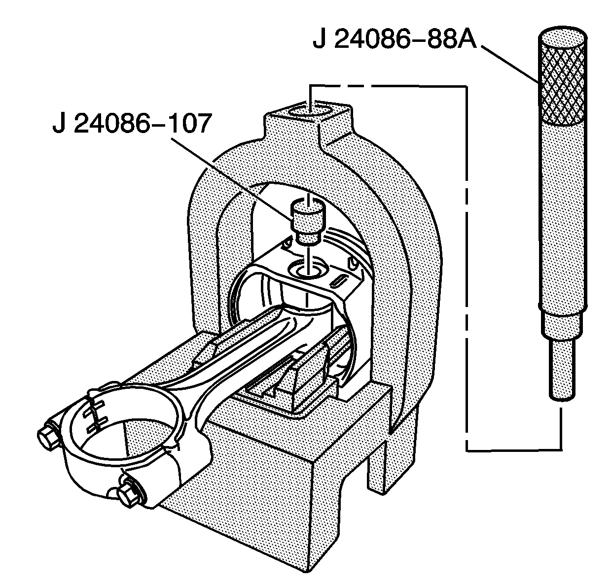
- Install the piston and connecting rod
assembly onto the J 24086-10.
- Install the J 24086-107 adapter onto the piston pin, and
install the J 24086-88A through the J 24086-10 and onto the
J 24086-107.
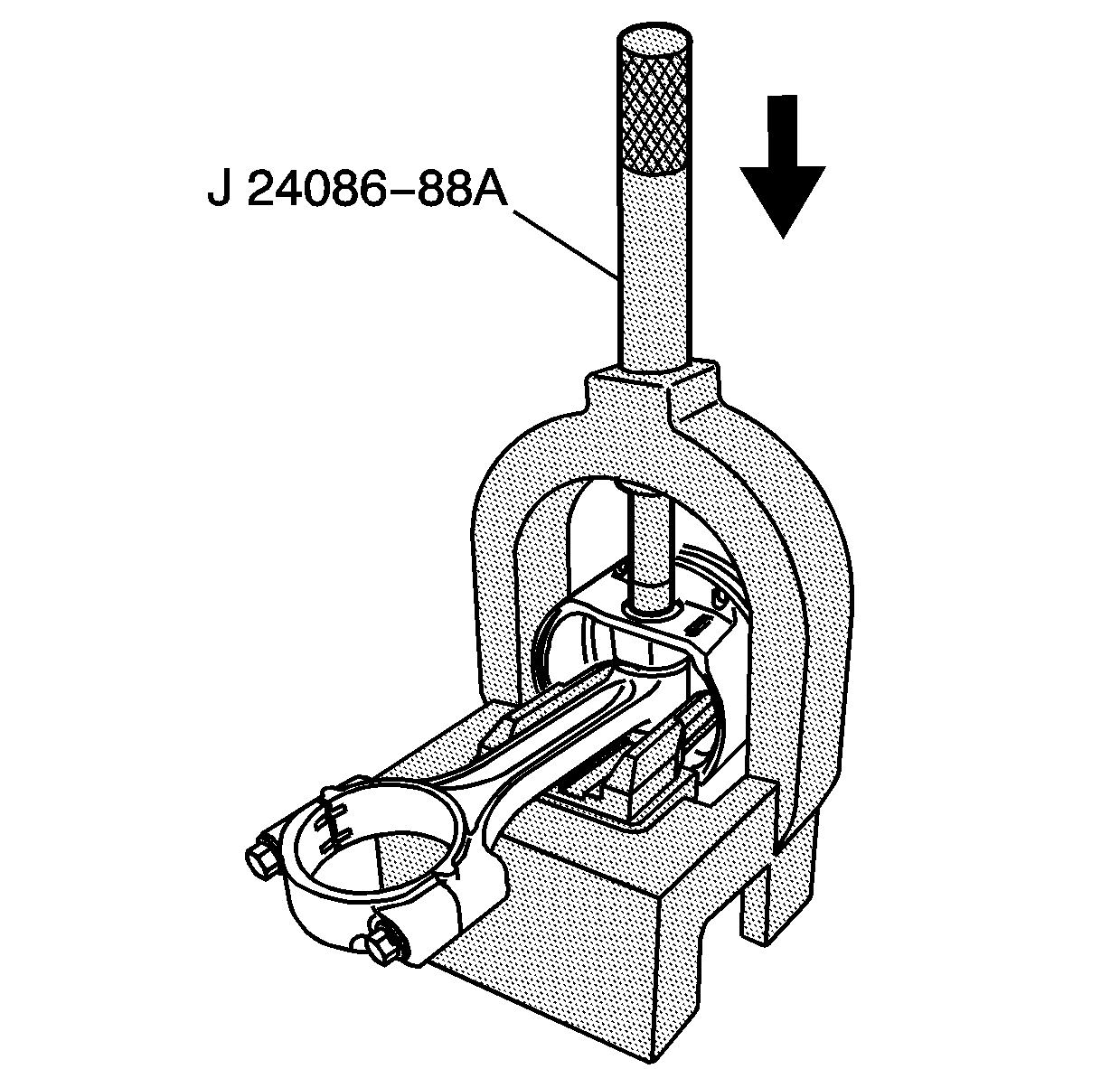
Important: The piston and pin are a matched set and are not to be serviced separately.
- Press the piston pin from the piston and connecting rod assembly.
Piston and Connecting Rod Assemble

- Install the J 24086-310 fork insert
into the J 24086-10 fixture support assembly.
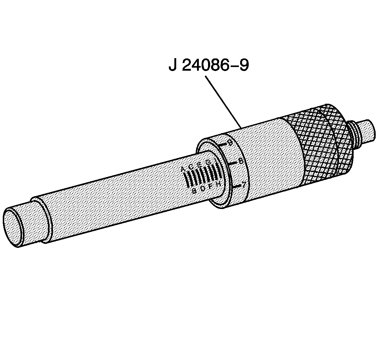
- Adjust the J 24086-9 installation
pin to the following setting: G-7.
Caution: Avoid contact with HOT components. Wear safety glasses and protective
heat gloves to avoid personal injury!
Notice: Applying excessive heat to the connecting rod may damage or distort
the connecting rod or piston. Connecting rod temperatures should not exceed
320°C (612°F).
- Using a connecting rod kiln, heat the piston pin end of the connecting
rod to 320°C (612°F).
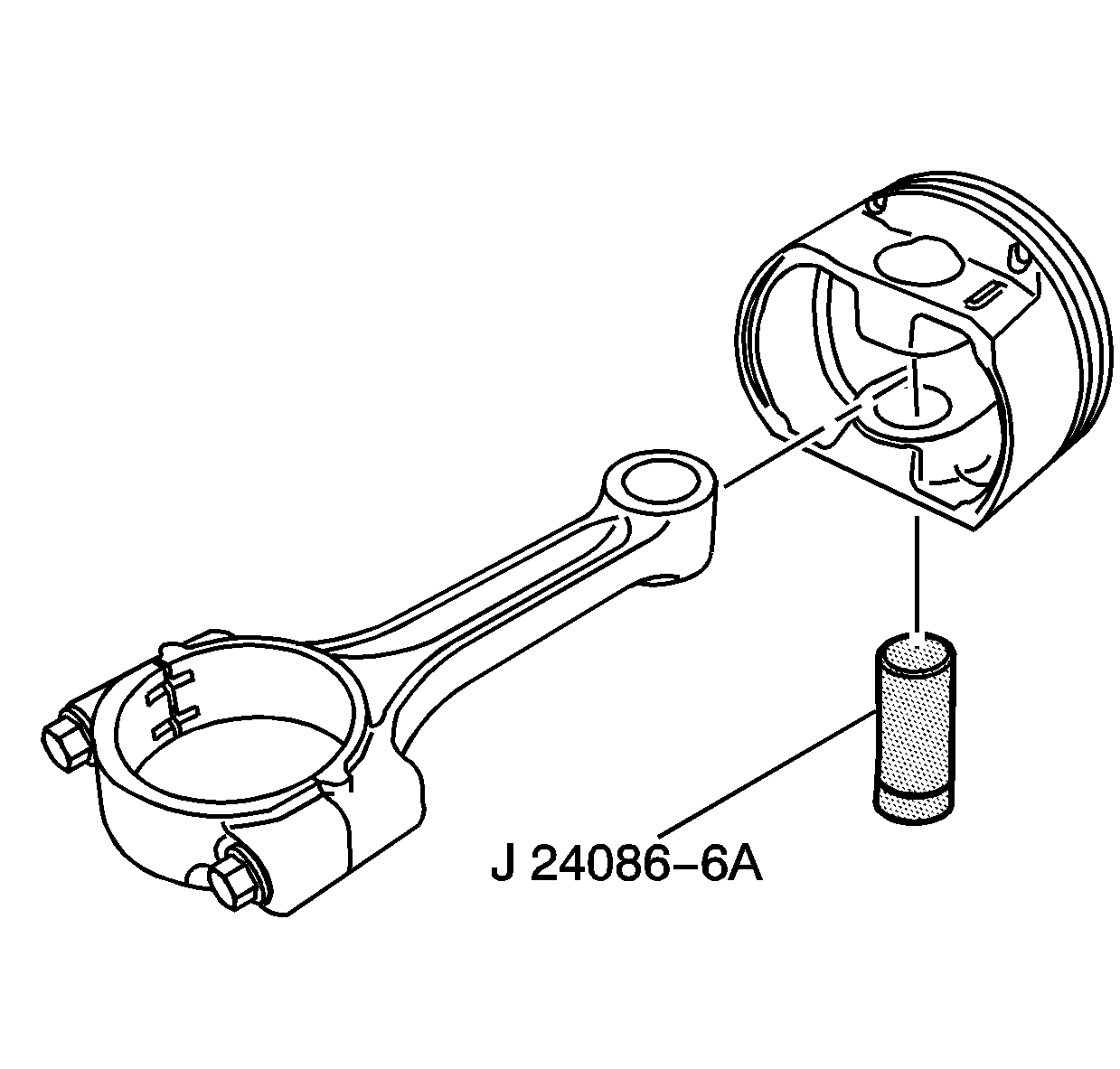
- Refer to the above illustration. Assemble
the piston, the connecting rod, and the J 24086-6A adapter as shown.
Insert the piston and connecting rod assembly into the J 24086-10
fixture support assembly.
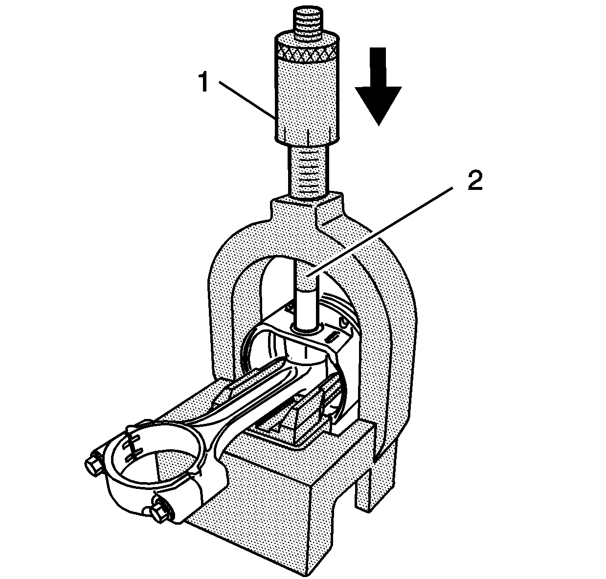
Notice: After the J 24086-9 installation pin bottoms on the J 24086-10
fixture support assembly, do not exceed a pressure of 35,000 kPa (5,000 psi),
or damage to the connecting rod press may result.
- Refer to the above illustration. Install the J 24086-105 (2)
onto the piston pin. Position the J 24086-9 (1) though the J 24086-10
fixture support assembly and onto the J 24086-105 (2).
- Press the J 24086-9 (1) installation pin until it bottoms
on the J 24086-10 fixture support assembly.
- Reinstall the piston rings onto the new piston. Refer to the Engine
Repair Section of the Service Manual for proper ring gap positioning.
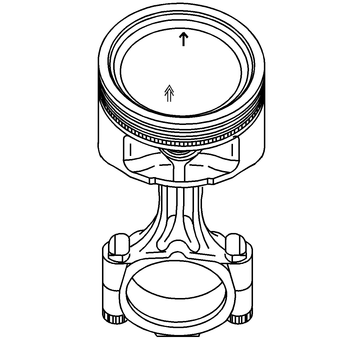
- Refer to the above illustration. Install
the assembled piston and rod assembly into the engine. Verify that the directional
arrows on the top of the piston point to the front of the engine.
- Follow the remaining engine assembly instructions found in the
Engine Mechanical Section of the Service Manual.


