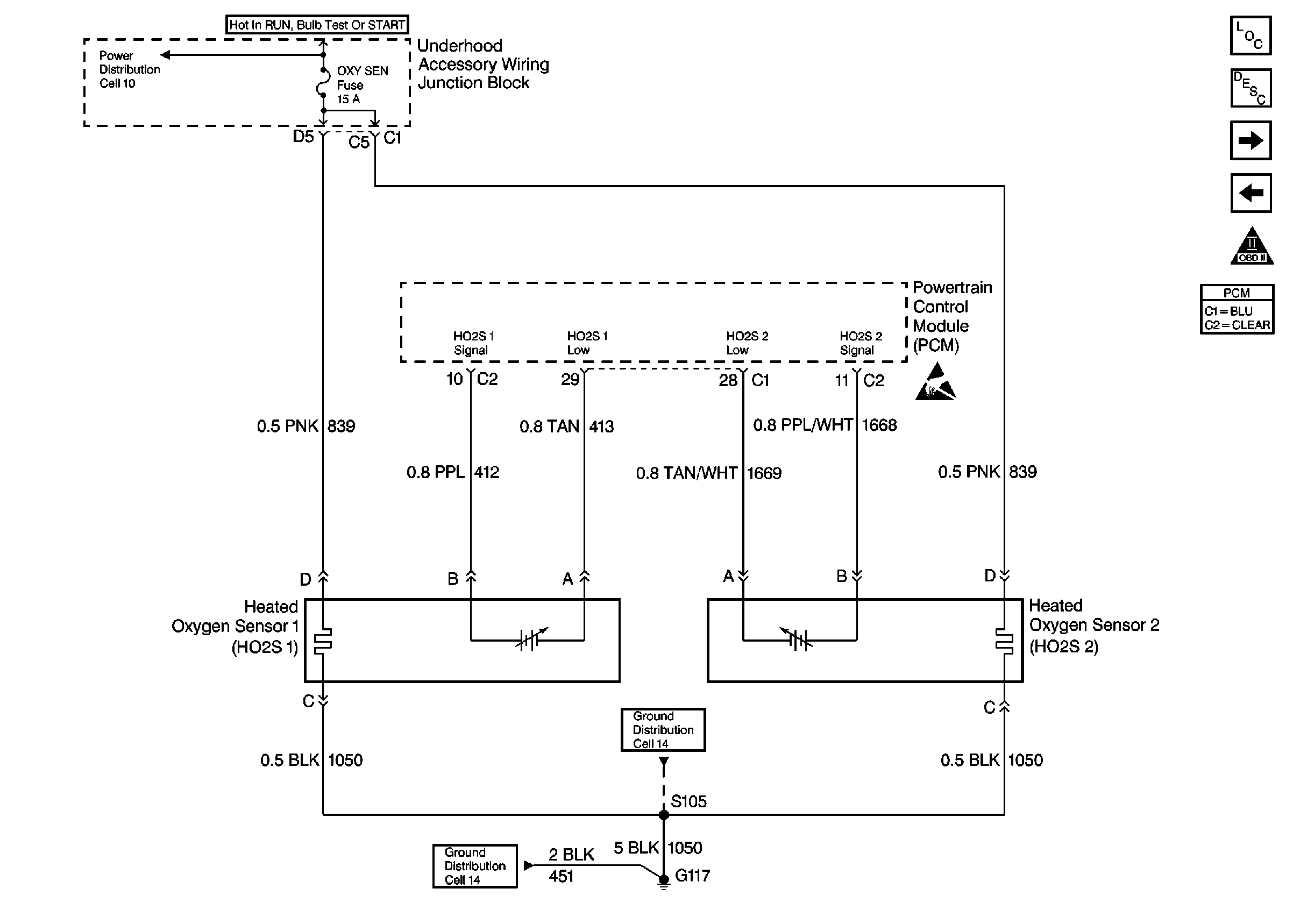
Refer to Engine Controls Schematics
Cell 20: Engine Data Sensors-HO2S 1 and HO2S 2
.
Circuit Description
The PCM supplies a bias voltage of about 450 mV between the HO2S signal and low circuits. When measured with a 10 megaohm digital voltmeter, this may display as low as 320 mV. The oxygen sensor varies the voltage within a range of about 1000 mV when the exhaust is rich, down through about 10 mV when exhaust is lean. The PCM constantly monitors the HO2S signal during closed loop operation and compensates for a rich or lean condition by decreasing or increasing injector pulse width as necessary. If the HO2S 1 voltage remains at or near the 450 mV bias for an extended period of time, DTC P0134 will be set, indicating an open sensor signal or sensor low circuit.
Conditions for running the DTC
| • | No active TP, MAP, MAF, ECT, IAT, CKP Sensor, misfire, fuel injector circuit, EVAP, Fuel trim, EGR, or DTCs present. |
| • | System voltage above 9.0 V. |
| • | Engine run time longer than 200 seconds. |
| • | Engine Coolant Temperature greater than 50°C (122°F) |
Conditions for Setting the DTC
HO2S 1 signal voltage remains between 400 mV and 500 mV for longer than 29 seconds.
Action Taken When the DTC Sets
| • | The PCM illuminates the malfunction indicator lamp (MIL) on the second consecutive ignition cycle that the diagnostic runs and fails. |
| • | The PCM records the operating conditions at the time the diagnostic fails. The first time the diagnostic fails, the PCM stores this information in the Failure Records. If the diagnostic reports a failure on the second consecutive ignition cycle, the PCM records the operating conditions at the time of the failure. |
| • | The PCM writes the conditions to the Freeze Frame and updates the Failure Records. |
Conditions for Clearing the MIL/DTC
| • | The PCM will turn OFF the malfunction indicator lamp (MIL) during the third consecutive trip in which the diagnostic has run and passed. |
| • | The history DTC will clear after 40 consecutive warm-up cycles have occurred without a malfunction. |
| • | The DTC can be cleared by using a scan tool. |
Diagnostic Aids
Check for the following conditions:
Faulty HO2S heater or heater circuit. With the ignition ON, engine OFF, the HO2S voltage displayed on a scan tool should gradually drop to below 250 mV or rise to above 600 mV. If not, disconnect the HO2S and connect a test light between the HO2S ignition feed and heater ground circuits. If the test light does not light, repair the open ignition feed or sensor ground circuit as necessary. If the test light lights and the HO2S signal and low circuits are OK, replace the HO2S.
Important: : Remove any debris from the connector surfaces before servicing a component. Inspect the connector gaskets when diagnosing or replacing a component. Ensure that the gaskets are installed correctly. The gaskets prevent contaminate intrusion.
| • | Poor terminal connection. |
| Inspect the harness connectors for backed out terminals, improper mating, broken locks, improperly formed or damaged terminals, and faulty terminal to wire connection. Use a corresponding mating terminal to test for proper tension. Refer to Intermittents and Poor Connections Diagnosis , and Connector Repairs Wiring Systems. |
| • | Damaged harness. |
| Inspect the wiring harness for damage. If the harness appears to be OK, observe the sensor display on the scan tool while moving connectors and wiring harnesses related to the sensor. A change in the sensor display may indicate the location of the fault. Refer to Wiring Repairs in Wiring Systems. |
| • | Inspect the PCM and the engine grounds for clean and secure connections. |
If the DTC is determined to be intermittent, reviewing the Fail Records can be useful in determining when the DTC was last set.
Test Description
Number(s) below refer to the step number(s) on the Diagnostic Table:
Step
| Action | Value(s) | Yes | No |
|---|---|---|---|---|
1 | Did you perform the Powertrain On Board Diagnostic (OBD) System Check? | -- | ||
2 |
Does scan tool indicate HO2S 1 voltage varying outside the specified values? | 400-500 mV | ||
3 |
Does scan tool indicate DTC failed this ignition? | -- | Go to Diagnostic Aids | |
4 |
Is HO2S 1 voltage below the specified value? | 150 mV | ||
5 |
Does HO2S 1 signal voltage measure above the specified value? | 450 mV | ||
6 |
Was an HO2S 1 low circuit problem found and corrected? | -- | ||
7 |
Was a HO2S 1 signal circuit problem found and corrected? | -- | ||
8 | Test for a poor HO2S 1 signal or low circuit terminal connection at the HO2S 1 harness connector and replace terminal(s) if necessary. Refer to Testing for Continuity , Intermittents and Poor Connections Diagnosis , Repairing Connector Terminals , and Connector Repairs . Did any terminals require replacement? | -- | ||
9 | Test for poor HO2S 1 low circuit terminal connection at the PCM and replace terminal if necessary. Refer to Connector Repairs . Did the terminal require replacement? | -- | ||
10 | Test for poor HO2S 1 signal circuit terminal connection at the PCM and replace terminal if necessary. Refer to Intermittents and Poor Connections Diagnosis . Did the terminal require replacement? | -- | ||
11 | Replace HO2S Refer to Heated Oxygen Sensor Replacement . Is the action completed? | -- | -- | |
|
Important: : Replacement PCM must be programmed. Replace the PCM. Refer to Powertrain Control Module Replacement/Programming . Is the action complete? | -- | -- | ||
13 |
Does scan tool indicate DTC failed this ignition? | -- | System OK |
