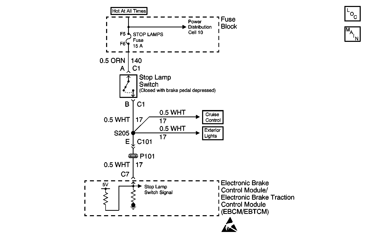
Circuit Description
This DTC is used to detect an open Stoplamp Switch in the non-ABS mode. The EBCM/EBTCM looks for a deceleration rate that would indicate braking action and verifies this assumption by requiring several repeats of this detection method. In each case, TCS will not be available since no Stoplamp Switch voltage is seen by the EBCM/EBTCM.
Conditions for Setting the DTC
DTC C1291 is set after the stoplamp switch remains open for three deceleration cycles. A deceleration cycle includes starting at a speed greater than 24 km/h (15 mph), then the vehicle must decelerate to 8 km/h (5 mph) for 2 seconds. The vehicle must then reach a speed less than 16 km/h (10 mph) to complete a deceleration cycle.
Action Taken When the DTC Sets
| • | A malfunction DTC is stored. |
| • | TCS is disabled. |
| • | Traction Control indicator is turned on. |
| • | ABS remains functional. |
Conditions for Clearing the DTC
| • | Condition for DTC is no longer present and scan tool clear DTC function is used. |
| • | 100 ignition cycles have passed with no DTCs detected. |
Diagnostic Aids
| • | Possible causes: |
| - | Stoplamp switch contacts open. |
| - | Stoplamp switch fuse open. |
| - | Stoplamp switch misadjusted. |
| - | Stoplamp switch fuse power feed circuit open. |
| • | It is very important that a thorough inspection of the wiring and connectors be performed. Failure to carefully and fully inspect wiring and connectors may result in misdiagnosis, causing part replacement with reappearance of the malfunction. |
| • | If any Wheel Speed Sensor DTCs are present you must diagnose them first. |
| • | An intermittent malfunction is most likely caused by a poor connection, rubbed through wire insulation, or a wire that is broken inside the insulation. |
Step | Action | Value(s) | Yes | No |
|---|---|---|---|---|
1 | Was the Diagnostic System Check performed? | -- | ||
2 | Press the brake pedal. Do the brake lights come on? | -- | ||
3 |
Is the voltage within the range specified in the values column? | 10.0-14.0 V | ||
4 | Check the STOP LAMPS fuse in the instrument panel electrical center. Is the fuse OK? | -- | ||
5 |
Is the voltage within the range specified in the value(s) column? | 10.0-14.0 V | ||
6 | Connect a fused jumper wire between terminals A and B of the Stoplamp switch harness connector. Do the brake lamps come on? | -- | ||
7 | Repair CKT 140 for an open or high resistance. Refer to Wiring Repairs in Wiring Systems. Is the repair complete? | -- | -- | |
8 |
Is CKT 140 continuous to ground? | -- | ||
9 | Repair the short to ground in CKT 140. Is the repair complete? | -- | -- | |
10 |
Is CKT 17 continuous to ground? | -- | ||
11 | Adjust or replace the Stoplamp switch as necessary. Refer to Stop Lamp Switch Adjustment or Stop Lamp Switch Replacement in Hydraulic Brakes. Is the repair complete? | -- | -- | |
12 | Repair CKT 17 for a short to ground. Is the repair complete? | -- | -- | |
13 | Replace the EBCM/EBTCM. Refer to Electronic Brake Control Module/Electronic Brake and Track Control Module Replacement . Is the replacement complete? | -- | -- | |
14 | Repair CKT 17 for an open between splice S205 and the EBCM/EBTCM. Is the repair complete? | -- | -- | |
15 | Repair CKT 17 for an open between the stop lamp switch connector and splice S205. Is the repair complete? | -- | -- |
